Rickard MLM RF User manual

1
RICKARD 2018
MLM RF OPERATION MANUAL
MLM RF WIRELESS WALL
THERMOSTAT & POD SENSOR
OPERATING MANUAL
MLM RF WIRELESS WALLMLM RF WIRELESS WALLMLM RF WIRELESS WALL
THERMOSTAT & POD SENSORTHERMOSTAT & POD SENSORTHERMOSTAT & POD SENSOR
OPERATING MANUALOPERATING MANUALOPERATING MANUAL

2
RICKARD 2018
MLM RF OPERATION MANUAL
Table of Abbreviations
AP Access Point RF base station module
ED End Device RF Wallstat or POD Sensor
LI Link Remote device mode
LIM Link Mode MLM Tool mode
MLM Multi Loop Modular VAV distributed control system
RF Radio Frequency
PS POD Sensor RF thermostat no display
RSSI Receive Signal Strength Indication Signal strength
SA Share Address Mode Remote Device mode
SAM Share Address Mode MLM Tool mode
SP Set Point Temperature control point
WS RF Wallstat RF wall mounted Thermostat with LCD
MCTI Maximum Communication Transmit Interval
Table of Contents
Table of Abbreviations 2
MLM RF Overview 3
Installation and Commissioning 3
Hardware Installation 3
The RF binding process 6
Discover the RF end devices 7
Grouping the Remote units 11
Verify and Replace End Devices 14
Removing an End Device 16
Moving End Device to a different Zone 17
Wallstat Operation 19
Adjust the Wallstat Setpoint 19
19 Set the Wallstat MENU Options
Installing the RF devices 6
Option 1 – Set the Wallstat RTC settings 20
POD Sensor Operation 22
Put the Wallstat in sleep mode (Default off state) 21
Option 2 – Set the Wallstat display for Batt/RSSI 21

3
RICKARD 2018
MLM RF OPERATION MANUAL
MLM RF Overview
The MLM RF consists of the following hardware units: an Access Point, the RF Wall Thermostat (Wallstat) and a RF
POD Sensor. This hardware unit in combination with the MLM Tool application software, revision 8.16 or later, com-
prise the MLM RF system.
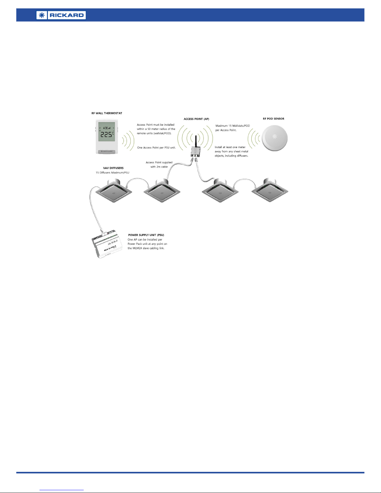
The MLM RF system allows for the remote placement of Wall thermostats and POD sensors without any cabling re-
strictions. The installation will typically comprise of one Access point per Power Supply Unit connecting remotely to a
maximum of 15 Wall Thermostats or POD Sensors, allowing for up to 60 remote units per MCU. See ‘MLM 24 RF In-
stallation Diagram’ below:
The Access point is powered by the MLM bus. The remote RF units are each powered by a pair of Lithium AAA bat-
teries, with a typical operational life of 3- 5 years. To conserve power, the RF communication between units is adap-
tive and could vary between 1 and a maximum of 20 minutes (the default maximum is set at 10 minutes), depending
on the operational requirements of the control system. During commissioning however, this period is reduced to
once a minute.
Adaptive Communication
In order for the RF End Device (ED) to conserve power an adaptive communication interval has been implemented
between the ED and AP.
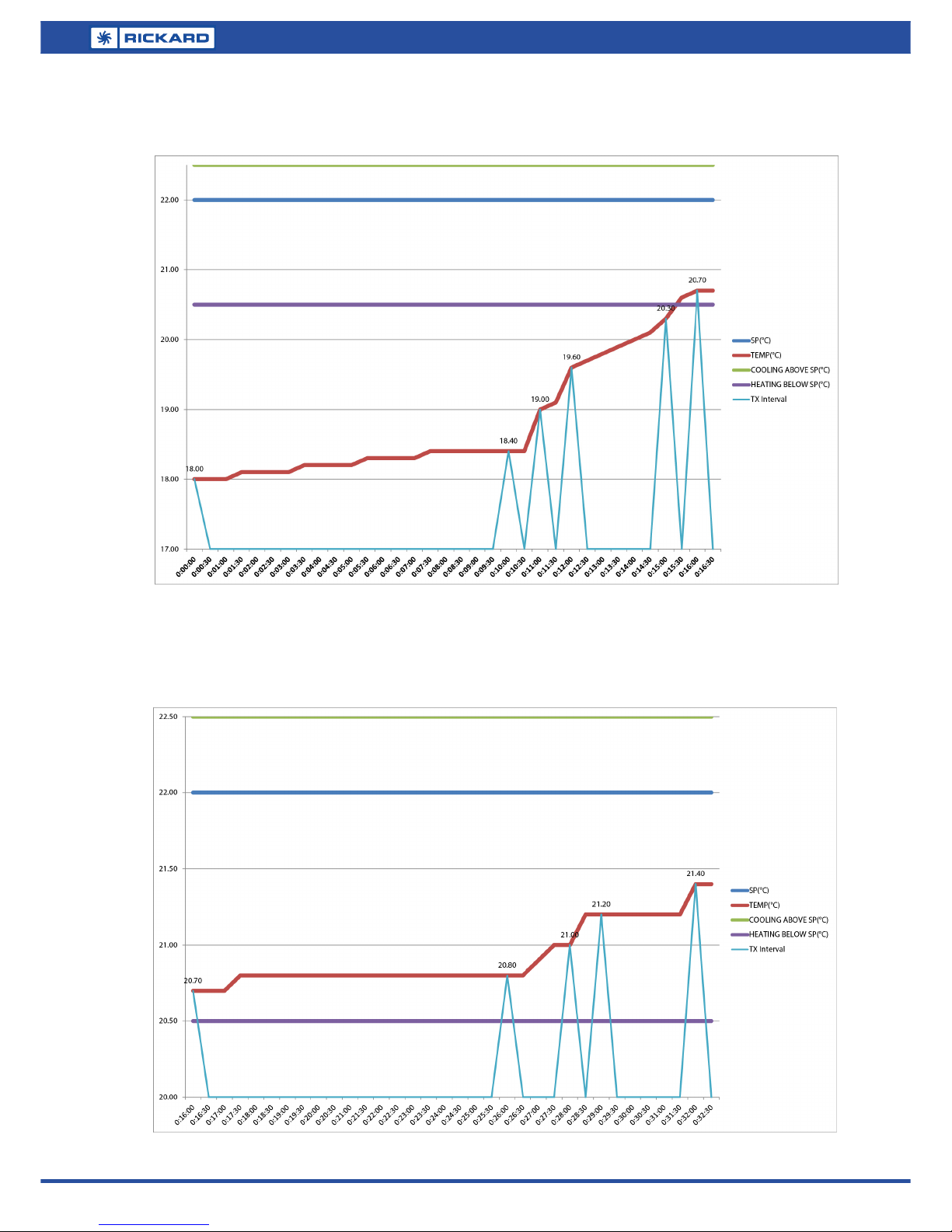
For a room temperature between 0.5°C above and 1.5°C below Setpoint, the ED response is more ‘active’. In this sce-
nario, the ED will transmit information to the Access Point for every 0.2°C change in room temperature, at 1 minute
intervals. If the temperature change is less than 0.2 °C for the entire duration of the Maximum Communication Trans-
mit Interval (MCTI), the ED will transmit every MCTI minutes. The MCTI can be set via MLM Application for each ED
to a maximum of 20 minutes.
For a room temperature above 0.5°C and below 1.5°C from Setpoint, the ED response is more ‘passive’. The ED will
transmit information to the Access Point for every 0.5°C temperature change in room temperature, at 1 minute inter-
vals. If the temperature change is less than 0.5°C for the entire duration of the Maximum Communication Transmit
Interval (MCTI), the ED will transmit every MCTI minutes.
The two graphs below shows communication in the ‘active and ‘passive’ regions. In this instance the MCTI is set to
the default of 10 minutes, but can be set between 1 and 20 minutes. Increasing the MCTI value will significantly in-
crease the battery life of the ED.

4
RICKARD 2018
MLM RF OPERATION MANUAL
The graph below shows the EP transmit response with Room Temperature changing from the ‘passive’ into the
‘active’ region.
The graph below shows the response inside the ‘active’ band. Note with a temperature change below 0.2°C the
MCTI period is applicable.

5
RICKARD 2018
MLM RF OPERATION MANUAL
The following MLM RF hardware models are available:
BU2011-2 MLM 24 RF Access Point
BU2111-2 MLM 24 RF Wallstat
BU2211-2 MLM 24 RF Remote Thermostat
Installation and Commissioning
The MLM RF units are fitted onto a standard MLM 24 installation. It interfaces to the MCU 2 V6.20, with the
MLM Tool V8.16, used for commissioning and diagnostics.
Note that when reference is made in this document to the End Device it refers to both the Wallstat and POD
sensor devices, the main difference between devices being the Wallstat LCD display.
Hardware Installation
The RF system requires an AP (Access Point) to be installed within a 50 meter radius of the remote units, either
Wallstat or POD sensor. One AP can be installed per Power Pack unit at any point on the MLM24 slave cabling
link. Ensure the AP is installed at a central vantage point, normally inside a ceiling void. Ensure the antennae
wire protruding from the AP enclosure is flexed in a vertical position. The AP is supplied with a 2m cable, install
at least one meter away from any sheet metal objects. Ensure the AP is securely fixed.
A maximum of 15 Wallstats or POD sensors can be installed per AP. Any combination of Wallstat and POD sen-
sor is allowed provided the total does not exceed 15 units. Please follow the installation instructions provided
indicating how to fit the remote unit back shell to a wall. Fit two of the correct battery types to each remote
unit, ensuring the correct polarity as indicated in pictures below. The batteries to be used are 1.5V AAA lithium
cells. Clip the remote unit onto the back shell. The remote unit will be in sleep mode with the LCD screen
switched off.
Battery Polarities
RF Wallstat RF POD Sensor

6
RICKARD 2018
MLM RF OPERATION MANUAL
Installing the RF devices
The following describes the process of installing the RF devices to the MLM network.
Installing the MLM network
Ensure the MLM network is powered up and running, with the MLM Tool connected to the section (MCU) con-
taining the RF units to be linked. Verify that all the wired nodes are visible in the MLM project. Select the edit
function in the MLM Tool and zone the diffusers into the required control zones. Verify that the Access Points
are visible on the MLM Tool as indicated. The diffusers should be in idle mode as no master controllers are se-
lected at this stage.
The RF binding process
The RF binding process is a three stage process designed to seamlessly integrate the RF end devices into the
MLM network. The three steps are as follows:
1. Discover - the Access point is activated to discover which RF end devices are visible to that Access Point.
2. Link – the discovered RF end devices are linked (saved) to the activated Access point.
3. Group –the linked RF end devices are connected to host diffusers, i.e. allocated to control zones.

7
RICKARD 2018
MLM RF OPERATION MANUAL
Discover the RF end devices
From the menu select ‘Wizards/Wireless/Link End Device’ as shown in this image.
Select the number of End Devices you need to discover for that Access Point. Should the End Device(s) that
needs to be discovered be in addition to previously linked devices, only enter the quantity of additional units.
A list of Access Points will show. Select the AP you wish to bind the end devices to and click Next.

8
RICKARD 2018
MLM RF OPERATION MANUAL
Click next
The Access Point is now ready to discover End Devices. The Access Point buzzer will beep periodically.
PressMENU/UPforat
least2secondstowake
upaWSfromsleepmode.
Theunitwillbrieflyenterthe‘SA’(save
address)modewiththedigits‘SA’
flashing.Noteiftheunitdoesnotexit
thismode,thecommunicaonlink
betweenAPandRemoteDeviceis
inadequate.
LinkMode:While
waingfortheAccess
PointtoLINK,thedigits
‘LI’andtheantennae
iconwillflash.
The next step is to go to an End Device to be bonded to a particular Access Point. Note the End Device must
be in sleep mode - indicated by a blank display on the RF Wallstat. While in discover mode the RF end devices
will beep every 5 seconds.
MENUUP

9
RICKARD 2018
MLM RF OPERATION MANUAL
In the MLM Tool, the discovered quantity of End Devices will now be incrementally displayed.
Repeat the process with the RF end devices until all the units requiring connecting to the selected Access Point
is shown on the Discovered count.
Note at this stage the individual RF end devices are already in ‘Link’ mode and ready for the permanent linking
process to begin. The Access Point will stay in ‘discover’ mode to allow for all the RF end devices to be detect-
ed.
Once the Expected and Discovered counts are equal, the Link process will proceed automatically. Note the Ac-
cess Point now re-connects to the end devices in a permanent (Link) mode. This process can take a few minutes
to complete.

10
RICKARD 2018
MLM RF OPERATION MANUAL
During this process the Wallstat display will revert from Link mode to the normal operating mode. Note the
RSSI indicator in the top left display and the RF icon permanently on.
Once completed, the End Device icons are now grouped to the right of the Access Point on the MLM Tool Net-
work screen. Note also our linked End Device count matches the discovered count on the Access Point icon.

11
RICKARD 2018
MLM RF OPERATION MANUAL
Grouping the Remote units
The next step is to group each End Device to a specific diffuser in a control zone. By connecting an End Device
to a diffuser, it is grouped to the zone that diffuser belongs to. Any one diffuser in a zone can be selected to
bind an End Device to that zone.
To group a single End Device to a particular diffuser, right click on the diffuser icon and follow the Wireless/
Group link.
To group multiple End Devices, right click on the Access Point icon and follow the Wireless/Group All link.

12
RICKARD 2018
MLM RF OPERATION MANUAL
From the listed diffusers, select a diffuser in the required zone to group the End Device to. Note the zone num-
bers are indicated for easy selection.
Under the Wallstats heading, select the tab directly opposite the selected diffuser (zone) and choose an End De-
vice from the dropdown list.
Press OK once all the End Devices are selected. The final binding configuration is now being saved.

13
RICKARD 2018
MLM RF OPERATION MANUAL
The End Devices are now grouped to their respective zones as shown in the Physical view..
The diffuser control modes will now exit idle mode for active control operation.

14
RICKARD 2018
MLM RF OPERATION MANUAL
Verify and Replace End Devices
To check the RF network status and health, select ‘Wizards/Access Point/ RF Network Status’.
The Network Status Display is divided into two parts. The top part displays the Access Point status, listing a
maximum of 4 Access Points on the network (one per channel). Battery and RSSI status indicated as ‘High’
means the level detected for the End Devices connected to that Access Point is ok, with a ‘Low’ requiring identi-
fication of the particular End Device in the bottom half of the screen.
The bottom part lists all the End Devices on the network. Note the yellow background for the battery voltage of
the top Wallstat indicates the battery status low but still ok. A red background will indicate battery status low.

15
RICKARD 2018
MLM RF OPERATION MANUAL
To conserve power, the transmit intervals from End Devices to the Access Point is adapted to the operational
requirements, alternating from a few seconds to a maximum of 10 minutes. The 3rd Wallstat listed here indi-
cates a transmit interval of 1210 seconds, flagged in yellow to indicate a communications break between Access
Point and Wallstat.
Should the communication break exceed 22 minutes, the interval field will be flagged in red, which effectively
means communication loss between Access Point and Wallstat.
Indicated below is a Wallstat shown after a timed out communication (bottom). Notice the room temperature of
zero degrees on the Wallstat icon with the diffuser in heating mode. After a minute the diffuser will revert to a
neutral (idle) mode with re-heater switched off.

16
RICKARD 2018
MLM RF OPERATION MANUAL
Removing an End Device
To remove a faulty or not responding End Device from the network, click on Wizards/Access Point/Refresh Net-
work.
Select the Access Point of Interest
Press the ‘Next’ button. Note this action involves entering the ‘Link’ mode again and in the process any non-
responsive End Devices will not show up on the count list. Allow up to 10 minutes for this process as the End
Device’s adaptive response time could be set at 10 minutes.
The number of paired devices is now reduced to two.

17
RICKARD 2018
MLM RF OPERATION MANUAL
Save the two End Devices to the network.
The two Wallstats that were already Linked and zoned have retained their zone positions, with the unresponsive
Wallstat removed. Note this process involved a network reset with the diffusers shown in the initialize state.
Moving End Device to a different Zone
To re-zone a Wallstat, click on the Wallstat icon, select Wireless/Un-Group.. and then ‘OK’. Wait for the new con-
figuration to be saved.

18
RICKARD 2018
MLM RF OPERATION MANUAL
The un-zoned Wallstat is now shown to the right of the Access Point.
Click on the Wallstat icon. The zoning process can now proceed as indicated below.

19
RICKARD 2018
MLM RF OPERATION MANUAL
Wallstat Operation
Adjust the Wallstat Setpoint
DOWN
UP
EnsureRoomtemperature
isbeingdisplayed.
PressUP/DOWNtoadjusttheSP.The
adjustedsetpointvaluewillflashwith
‘SP’indicatedasshown.Wait5seconds
forthenewSPvaluetobeacceptedand
thedisplayreverttonormal.
MENU
Pressandholddown
MENUtoenterMENU
Sengs
MENU
PressMENUtoaccess
opon1(RTC)
MENU
PressMENUagainto
accessopon2
(Ba/RSSI)
Set the Wallstat MENU Options

20
RICKARD 2018
MLM RF OPERATION MANUAL
Option 1 – Set the Wallstat RTC settings
PressUP/DOWNtoadjust
theclockdisplayopons
NO/YES.
PressENTER(YES)toletthe
WSdisplaytheRTCvalues
ENTER
PressENTERtosetHH:MM:SS
ENTER
PressUP/DOWNtoedit
HH:MM:SSvalues.
Other manuals for MLM RF
1
Table of contents
Popular Accessories manuals by other brands

aquilar
aquilar AquiTron AT-OPSEN installation instructions

BOMANN
BOMANN KSG 238.1 instruction manual

PCB Piezotronics
PCB Piezotronics 622A01 Installation and operating manual

SunSetter
SunSetter VISTA Upgrade instructions

Resolution Products
Resolution Products RE619 quick start guide

EUTECH INSTRUMENTS
EUTECH INSTRUMENTS CYANIDE EPOXY instruction manual