RIDGID R851150 User manual

1
Your hammer drill has been engineered and manufactured to our high standards for dependability, ease of operation, and
operator safety. When properly cared for, it will give you years of rugged, trouble-free performance.
WARNING:
To reduce the risk of injury, the user must read and understand the operator’s manual before using this product.
Thank you for buying a RIDGID product.
SAVE THIS MANUAL FOR FUTURE REFERENCE
OPERATOR’S MANUAL
1/2 in., 24 VOLT LITHIUM-ION
HAMMER DRILL
TWO-SPEED/REVERSIBLE
R851150
NEW BATTERY PACKS MUST BE
CHARGED BEFORE FIRST USE

2
Introduction .....................................................................................................................................................................2
General Safety Rules ................................................................................................................................................... 3-4
Specific Safety Rules .......................................................................................................................................................4
Safety Rules for Charger .................................................................................................................................................5
Symbols ....................................................................................................................................................................... 6-7
Features ....................................................................................................................................................................... 8-9
Assembly .......................................................................................................................................................................10
Operation ................................................................................................................................................................. 11-20
Maintenance ............................................................................................................................................................ 21-22
Warranty ........................................................................................................................................................................23
Customer Service Information ......................................................................................................................... Back Page
TABLE OF CONTENTS
INTRODUCTION
This tool has many features for making its use more pleasant and enjoyable. Safety, performance, and dependability have
been given top priority in the design of this product making it easy to maintain and operate.
WARNING:
Some dust created by power sanding, sawing, grinding, drilling, and other construction activities contains chemicals
known to cause cancer, birth defects or other reproductive harm. Some examples of these chemicals are:
• lead from lead-based paints,
• crystalline silica from bricks and cement and other masonry products, and
• arsenic and chromium from chemically-treated lumber.
Your risk from these exposures varies, depending on how often you do this type of work. To reduce your exposure
to these chemicals: work in a well ventilated area, and work with approved safety equipment, such as those dust
masks that are specially designed to filter out microscopic particles.

3
GENERAL SAFETY RULES
WARNING!
Read all instructions. Failure to follow all
instructions listed below may result in electric
shock, fire and/or serious injury. The term “power
tool” in all of the warnings listed below refers
to your mains-operated (corded) power tool or
battery-operated (cordless) power tool.
SAVE THESE INSTRUCTIONS
WORK AREA SAFETY
Keep work area clean and well lit. Cluttered or dark
areas invite accidents.
Do not operate power tools in explosive atmospheres,
such as in the presence of flammable liquids, gases
or dust. Power tools create sparks which may ignite the
dust or fumes.
Keep children and bystanders away while operating a
power tool. Distractions can cause you to lose control.
ELECTRICAL SAFETY
Power tool plugs must match the outlet. Never modify
the plug in any way. Do not use any adapter plugs with
earthed (grounded) power tools. Unmodified plugs and
matching outlets will reduce risk of electric shock.
Avoid body contact with earthed or grounded surfaces
such as pipes, radiators, ranges and refrigerators.
There is an increased risk of electric shock if your
body is earthed or grounded.
Do not expose power tools to rain or wet conditions.
Water entering a power tool will increase the risk of
electric shock.
Do not abuse the cord. Never use the cord for
carrying, pulling or unplugging the power tool. Keep
cord away from heat, oil, sharp edges or moving
parts. Damaged or entangled cords increase the risk
of electric shock.
When operating a power tool outdoors, use an
extension cord suitable for outdoor use. Use of a cord
suitable for outdoor use reduces the risk of electric
shock.
Use battery only with charger listed.
MODEL BATTERY PACK CHARGER
R851150 130377001 140315001
(R85008) (R85009)
PERSONAL SAFETY
Stay alert, watch what you are doing and use common
sense when operating a power tool. Do not use a
power tool while you are tired or under the influence of
drugs, alcohol or medication. A moment of inattention
while operating power tools may result in serious personal
injury.
Use safety equipment. Always wear eye protection.
Safety equipment such as dust mask, non-skid safety
shoes, hard hat, or hearing protection used for appropriate
conditions will reduce personal injuries.
Avoid accidental starting. Ensure the switch is in the
off-position before plugging in. Carrying power tools
with your finger on the switch or plugging in power tools
that have the switch on invites accidents.
Remove any adjusting key or wrench before turning
the power tool on. A wrench or a key left attached to
a rotating part of the power tool may result in personal
injury.
Do not overreach. Keep proper footing and balance
at all times. This enables better control of the power tool
in unexpected situations.
Dress properly. Do not wear loose clothing or jewelry.
Keep your hair, clothing and gloves away from moving
parts. Loose clothes, jewelry or long hair can be caught
in moving parts.
If devices are provided for the connection of dust
extraction and collection facilities, ensure these are
connected and properly used. Use of these devices can
reduce dust-related hazards.
Do not wear loose clothing or jewelry. Contain long
hair. Loose clothes, jewelry, or long hair can be drawn
into air vents.
Do not use on a ladder or unstable support. Stable
footing on a solid surface enables better control of the
power tool in unexpected situations.
POWER TOOL USE AND CARE
Do not force the power tool. Use the correct power tool
for your application.
The correct power tool will do the job
better and safer at the rate for which it was designed.
Do not use the power tool if the switch does not turn
it on and off. Any power tool that cannot be controlled
with the switch is dangerous and must be repaired.
Disconnect the plug from the power source and/or
the battery pack from the power tool before making
any adjustments, changing accessories, or storing
power tools. Such preventive safety measures reduce
the risk of starting the power tool accidentally.
Store idle power tools out of the reach of children and
do not allow persons unfamiliar with the power tool
or these instructions to operate the power tool. Power
tools are dangerous in the hands of untrained users.
Maintain power tools. Check for misalignment or
binding of moving parts, breakage of parts and any
other condition that may affect the power tool’s
operation. If damaged, have the power tool repaired
before use. Many accidents are caused by poorly
maintained power tools.
Keep cutting tools sharp and clean. Properly maintained
cutting tools with sharp cutting edges are less likely to
bind and are easier to control.

4
GENERAL SAFETY RULES
SPECIFIC SAFETY RULES
Wear ear protectors with impact drills. Exposure to
noise can cause hearing loss.
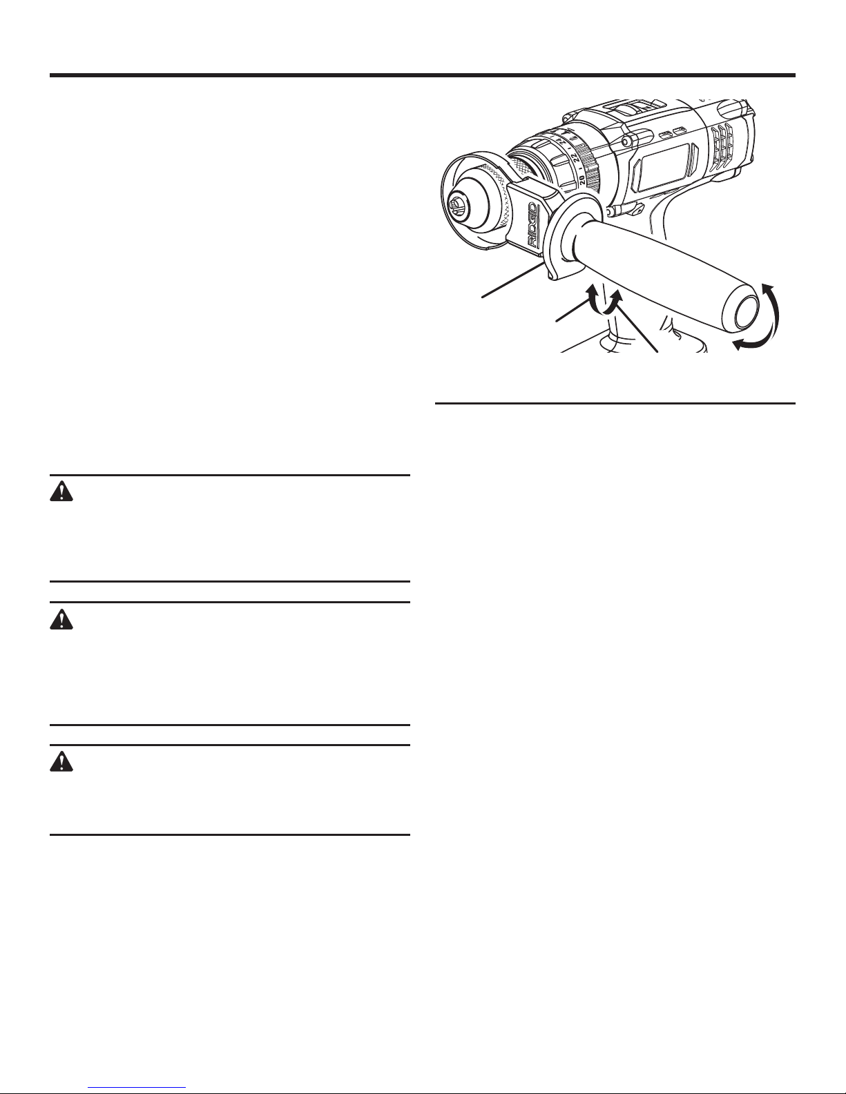
Use auxiliary handles supplied with the tool. Loss of
control can cause personal injury.
Hold power tools by insulated gripping surfaces when
performing an operation where the cutting tool may
contact hidden wiring or its own cord. Contact with a
“live” wire will also make exposed metal parts of the tool
“live” and shock the operator.
Know your power tool. Read operator’s manual
carefully. Learn its applications and limitations, as well
as the specific potential hazards related to this tool.
Following this rule will reduce the risk of electric shock,
fire, or serious injury.
Always wear safety glasses with side shields. Everyday
glasses have only impact resistant lenses. They are NOT
safety glasses. Following this rule will reduce the risk of
eye injury.
Protect your lungs. Wear a face or dust mask if the
operation is dusty. Following this rule will reduce the risk
of serious personal injury.
Protect your hearing. Wear hearing protection during
extended periods of operation. Following this rule will
reduce the risk of serious personal injury.
Battery tools do not have to be plugged into an
electrical outlet; therefore, they are always in
operating condition. Be aware of possible hazards
when not using your battery tool or when changing
accessories. Following this rule will reduce the risk of
electric shock, fire, or serious personal injury.
Do not place battery tools or their batteries near fire
or heat. This will reduce the risk of explosion and possibly
injury.
Do not crush, drop or damage battery pack. Do not
use a battery pack or charger that has been dropped
or received a sharp blow. A damaged battery is subject
to explosion. Properly dispose of a dropped or damaged
battery immediately.
Batteries vent hydrogen gas and can explode in the
presence of a source of ignition, such as a pilot light.
To reduce the risk of serious personal injury, never use
any cordless product in the presence of open flame. An
exploded battery can propel debris and chemicals. If
exposed, flush with water immediately.
Do not charge battery tool in a damp or wet location.
Following this rule will reduce the risk of electric shock.
For best results, your battery tool should be charged
in a location where the temperature is more than
50°F but less than 100°F. Do not store outside or in
vehicles.
Under extreme usage or temperature conditions,
battery leakage may occur. If liquid comes in contact
with your skin, wash immediately with soap and water,
then neutralize with lemon juice or vinegar. If liquid
gets into your eyes, flush them with clean water for
at least 10 minutes, then seek immediate medical
attention. Following this rule will reduce the risk of serious
personal injury.
If the power supply cord is damaged, it must be replaced
only by the manufacturer or by an authorized service
center to avoid risk.
Use the power tool, accessories and tool bits etc., in
accordance with these instructions and in the manner
intended for the particular type of power tool, taking
into account the working conditions and the work
to be performed. Use of the power tool for operations
different from those intended could result in a hazardous
situation.
BATTERY TOOL USE AND CARE
Ensure the switch is in the off position before inserting
battery pack. Inserting the battery pack into power tools
that have the switch on invites accidents.
Recharge only with the charger specified by the
manufacturer. A charger that is suitable for one type
of battery pack may create a risk of fire when used with
another battery pack.
Use power tools only with specifically designated
battery packs. Use of any other battery packs may create
a risk of injury and fire.
When battery pack is not in use, keep it away from
other metal objects like paper clips, coins, keys, nails,
screws, or other small metal objects that can make a
connection from one terminal to another. Shorting the
battery terminals together may cause burns or a fire.
Under abusive conditions, liquid may be ejected from
the battery, avoid contact. If contact accidentally
occurs, flush with water. If liquid contacts eyes,
additionally seek medical help. Liquid ejected from the
battery may cause irritation or burns.
SERVICE
Have your power tool serviced by a qualified repair
person using only identical replacement parts. This will
ensure that the safety of the power tool is maintained.
WARNING!
To reduce the risk of injury, user must read
instruction manual.
When servicing a power tool, use only identical
replacement parts. Follow instructions in the
Maintenance section of this manual. Use of unauthorized
parts or failure to follow Maintenance instructions may
create a risk of shock or injury.

5
SAFETY RULES FOR CHARGER
WARNING!
READ AND UNDERSTAND ALL INSTRUCTIONS.
Failure to follow all instructions listed below, may
result in electric shock, fire and/or serious personal
injury.
Before using battery charger, read all instructions and
cautionary markings in this manual, on battery charger,
battery, and product using battery to prevent misuse of
the products and possible injury or damage.
CAUTION:
To reduce the risk of electric shock or damage to
the charger and battery, charge only lithium-ion
rechargeable batteries as specifically designated
on your charger. Other types of batteries may
burst, causing personal injury or damage.
Do not use charger outdoors or expose to wet or damp
conditions. Water entering charger will increase the risk
of electric shock.
Use of an attachment not recommended or sold by the
battery charger manufacturer may result in a risk of
fire, electric shock, or injury to persons. Following this
rule will reduce the risk of electric shock, fire, or serious
personal injury.
Do not abuse cord or charger. Never use the cord to
carry the charger. Do not pull the charger cord rather than
the plug when disconnecting from receptacle. Damage
to the cord or charger could occur and create an electric
shock hazard. Replace damaged cords immediately.
Make sure cord is located so that it will not be stepped
on, tripped over, come in contact with sharp edges
or moving parts or otherwise subjected to damage or
stress. This will reduce the risk of accidental falls, which
could cause injury, and damage to the cord, which could
result in electric shock.
Keep cord and charger from heat to prevent damage
to housing or internal parts.
Do not let gasoline, oils, petroleum-based products,
etc. come in contact with plastic parts. They contain
chemicals that can damage, weaken, or destroy
plastic.
An extension cord should not be used unless
absolutely necessary. Use of improper extension cord
could result in a risk of fire and electric shock. If extension
cord must be used, make sure:
a. That pins on plug of extension cord are the
same number, size and shape as those of
plug on charger.
b. That extension cord is properly wired and in
good electrical condition; and
c. That wire size is large enough for AC ampere
rating of charger as specified below:
Cord Length (Feet) 25' 50' 100'
Cord Size (AWG) 16 16 16
NOTE: AWG = American Wire Gauge
Do not operate charger with a damaged cord or
plug, which could cause shorting and electric shock. If
damaged, have the charger replaced by an authorized
serviceman.
Do not operate charger if it has received a sharp blow,
been dropped, or otherwise damaged in any way.
Take it to an authorized serviceman for electrical check
to determine if the charger is in good working order.
Do not disassemble charger. Take it to an authorized
serviceman when service or repair is required. Incorrect
reassembly may result in a risk of electric shock or fire.
Unplug charger from outlet before attempting any
maintenance or cleaning to reduce the risk of electric
shock.
Disconnect charger from the power supply when
not in use. This will reduce the risk of electric shock or
damage to the charger if metal items should fall into the
opening. It also will help prevent damage to the charger
during a power surge.
Risk of electric shock. Do not touch uninsulated portion
of output connector or uninsulated battery terminal.
Save these instructions. Refer to them frequently and
use them to instruct others who may use this tool. If you
loan someone this tool, loan them these instructions also
to prevent misuse of the product and possible injury.
IMPORTANT SAFETY INSTRUCTIONS
1. SAVE THESE INSTRUCTIONS
This manual contains important safety and operating instructions for battery charger 140315001.
2. Before using battery charger, read all instructions and cautionary markings on battery charger, battery, and product
using battery.
3. CAUTION: To reduce the risk of injury, charge only lithium-ion rechargeable batteries. Other types of batteries may
burst, causing personal injury or damage.

6
SYMBOLS
Some of the following symbols may be used on this tool. Please study them and learn their meaning. Proper interpretation
of these symbols will allow you to operate the tool better and safer.
V Volts Voltage
A Amperes Current
Hz Hertz Frequency (cycles per second)
W Watt Power
min Minutes Time
Alternating Current Type of current
Direct Current Type or a characteristic of current
n
o
No Load Speed Rotational speed, at no load
Class II Tool Double-insulated construction
.../min Per Minute Revolutions, strokes, surface speed, orbits etc., per minute
Wet Conditions Alert Do not expose to rain or use in damp locations.
Read The Operator’s Manual To reduce the risk of injury, user must read and understand
operator’s manual before using this product.
Eye Protection Always wear safety goggles or safety glasses with side shields and,
as necessary, a full face shield when operating this product.
Safety Alert Precautions that involve your safety.
No Hands Symbol Failure to keep your hands away from the blade will result in serious
personal injury.
No Hands Symbol Failure to keep your hands away from the blade will result in serious
personal injury.
No Hands Symbol Failure to keep your hands away from the blade will result in serious
personal injury.
No Hands Symbol Failure to keep your hands away from the blade will result in serious
personal injury.
Hot Surface To reduce the risk of injury or damage, avoid contact with any hot
surface.
SYMBOL NAME DESIGNATION/EXPLANATION

7
SYMBOLS
SERVICE
Servicing requires extreme care and knowledge and should
be performed only by a qualified service technician. For
service we suggest you return the product to your nearest
AUTHORIZED SERVICE CENTER for repair. When servic-
ing, use only identical replacement parts.
WARNING:
To avoid serious personal injury, do not attempt
to use this product until you read thoroughly and
understand completely the operator’s manual.
If you do not understand the warnings and
instructions in the operator’s manual, do not use
this product. Call RIDGID customer service for
assistance.
The operation of any power tool can result in foreign objects being thrown into your eyes, which can result
in severe eye damage. Before beginning power tool operation, always wear safety goggles or safety glasses
with side shields and, when needed, a full face shield. We recommend Wide Vision Safety Mask for use
over eyeglasses or standard safety glasses with side shields. Always use eye protection which is marked
to comply with ANSI Z87.1.
WARNING:
SAVE THESE INSTRUCTIONS
The following signal words and meanings are intended to explain the levels of risk associated with this product.
DANGER: Indicates an imminently hazardous situation, which, if not avoided, will result
in death or serious injury.
WARNING: Indicates a potentially hazardous situation, which, if not avoided, could result
in death or serious injury.
CAUTION Indicates a potentially hazardous situation, which, if not avoided, may result in
minor or moderate injury.
CAUTION (Without Safety Alert Symbol) Indicates a situation that may result in property
damage.
SYMBOL SIGNAL MEANING

8
FEATURES
PRODUCT SPECIFICATIONS
Chuck ...........................................................1/2 in. Keyless
Motor .................................................................. 24 Volt DC
Switch .............................. VSR (Variable Speed Reversible)
No Load Speed ....................... 0-400/0-1,500 r/min. (RPM)
Blows per minute ........................... 0-6,400/0-24,000 BPM
Clutch ................................................................ 24 Position
Torque ................................................................... 615 in.lb.
Charger Input ................................... 120 V, 60 Hz, AC only
DIRECTION OF ROTATION
SELECTOR (FORWARD/REVERSE/
CENTER LOCK)
KEYLESS
CHUCK
BATTERY
PACK
SWITCH
TRIGGER
FORWARD
REVERSE
AUXILIARY
HANDLE ASSEMBLY
MODE
CHANGE RING
TWO-SPEED
GEAR TRAIN
Fig. 1
TORQUE
ADJUSTMENT
RING
CHARGER
4-1/8 in.
“KEY HOLE”
HANGER

9
FEATURES
KNOW YOUR HAMMER DRILL
See Figure 1.
The safe use of this product requires an understanding of
the information on the tool and in this operator’s manual as
well as a knowledge of the project you are attempting. Before
use of this product, familiarize yourself with all operating
features and safety rules.
AUXILIARY HANDLE ASSEMBLY
Your drill is equipped with an auxiliary handle assembly for
ease of operation and to prevent loss of control.
BLOWS PER MINUTE
This tool features an impact speed of 0-6,400 BPM in LO
(1) speed and 0-24,000 BPM in HI (2) speed. BPM (Blows
Per Minute) is the number of impacts per minute.
CHARGER
The charger has a key-hole hanging feature for convenient,
space-saving storage. Screws should be installed so that
the center distance is 4-1/8 in.
DIRECTION OF ROTATION SELECTOR
(FORWARD/REVERSE/CENTER LOCK)
Your drill has a direction of rotation (forward/reverse/center
lock) selector located above the switch trigger for changing
the direction of bit rotation. Setting the switch trigger in the
OFF (center lock) position helps reduce the possibility of
accidental starting when not in use.
MODE CHANGE RING
Using the mode change ring, the operator can select either
hammer mode, drive mode, or drilling mode.
KEYLESS CHUCK
The keyless chuck allows you to hand-tighten or release the
drill bit in the chuck jaws.
TORQUE ADJUSTMENT RING
Your drill has a 24-position clutch. The torque adjustment
ring can be turned to select the right amount of torque for
your application.
TWO-SPEED GEAR TRAIN
The two-speed gear train is designed for drilling or driving
at LO (1) or HI (2) speeds. A slide switch is located on top
of your drill for selecting either LO (1) or HI (2) speed.
VARIABLE SPEED
The variable speed switch trigger delivers higher speed with
increased trigger pressure and lower speed with decreased
trigger pressure.

10
UNPACKING
This product requires assembly.
Carefully remove the tool and any accessories from the
box. Make sure that all items listed in the packing list are
included.
Inspect the tool carefully to make sure no breakage or
damage occurred during shipping.
Do not discard the packing material until you have care-
fully inspected and satisfactorily operated the tool.
If any parts are damaged or missing, please call
1-866-539-1710 for assistance.
PACKING LIST
Hammer Drill
Auxiliary Handle
Double-ended Bit
Tool Bag
Charger
Battery Pack
Operator's Manual
WARNING:
If any parts are damaged or missing do not operate
this tool until the parts are replaced. Failure to
heed this warning could result in serious personal
injury.
WARNING:
Do not attempt to modify this tool or create
accessories not recommended for use with this
tool. Any such alteration or modification is misuse
and could result in a hazardous condition leading
to possible serious personal injury.
WARNING:
To prevent accidental starting that could cause
serious personal injury, always remove the battery
pack from the tool when assembling parts.
ASSEMBLY
360°
ROTATION
TO
TIGHTEN
AUXILIARY
HANDLE
TO
LOOSEN Fig. 2
INSTALLING THE AUXILIARY HANDLE
ASSEMBLY
See Figure 2.
An auxiliary handle assembly is packed with the drill for
ease of operation and to help prevent loss of control. The
handle can be rotated 360°, and it can also be mounted on
the opposite side for left hand use.
To install the auxiliary handle assembly:
Loosen the handle assembly by turning the handle
counterclockwise.
Rotate the handle assembly to the desired operating
position.
Securely tighten by turning the handle assembly
clockwise.
Be sure the handle assembly is securely tightened against
the clamp. This secures the handle assembly.
NOTE: For convenience and ease of starting threads, the
hex nut has been trapped inside the molded slot in the
handle assembly.

11
WARNING:
Do not allow familiarity with tools to make you
careless. Remember that a careless fraction of a
second is sufficient to inflict severe injury.
WARNING:
Always wear safety goggles or safety glasses with
side shields when operating tools. Failure to do so
could result in objects being thrown into your eyes
resulting in possible serious injury.
WARNING:
Do not use any attachments or accessories
not recommended by the manufacturer of this
tool. The use of attachments or accessories not
recommended can result in serious personal
injury.
APPLICATIONS
You may use this tool for the purposes listed below:
Hammer drilling in concrete, brick, or other masonry
Drilling in wood
Drilling in ceramics, plastics, fiberglass, and laminates
Drilling in metals
Driving screws
Mixing paint
CAUTION:
If at any point during the charging process none
of the LEDs are lit, remove the battery pack from
the charger to avoid damaging the product. DO
NOT insert another battery. Return the charger and
battery to your nearest service center for service
or replacement.
CAUTION:
Charge in a well ventilated area. Do not block
charger vents. Keep them clear to allow proper
ventilation.
CHARGING THE BATTERY PACK
NOTE: New 24 Volt lithium-ion battery packs will not
work without first being charged. Before first time use,
charge the battery pack to activate it.
It is not necessary to drain the battery pack completely
before recharging. Lithium-ion battery packs have no
“memory” and can be recharged at any time. It is therefore
possible to charge the battery pack before extended usage
even if the battery pack is not completely drained of charge.
Use the charge level indicator to determine the amount of
charge in the battery pack.
Lithium-ion batteries deliver fade free power for their entire
run time. 24 Volt lithium-ion tools will not gradually lose
power due to decreasing battery charge. Instead, power from
the battery pack will drop from full to zero once the full charge
has been drained from the battery. Once this happens, the
tool’s power drops from full to zero, and recharging of the
battery is required
OPERATION
Fig. 3
CHARGE
LEVEL INDICATOR
24vXLi
?

12
OPERATION
TO CHARGE
A fully discharged battery pack with a temperature between
32° F (0° C) and 150° F (65° C) will charge in about an
hour.
Charge the 24 Volt lithium-ion battery pack only with the
charger provided.
� Connect the charger to a power supply.
NOTE:iIf needed, the charger can operate with most
generators and inverters rated at 300 Watts or higher.
Attach the battery pack to the charger by aligning the
raised ribs on the battery pack with the grooves in the
charger, then slide the battery pack onto the charger. See
Figure 3.
Do not place the charger in an area of extreme heat or
cold. It will work best at normal room temperature.
After charging is complete, the continuous green light
will come on and the charge level indicator lights on the
battery will go off.
The charger will keep the battery pack fully charged if left
on the charger.
CHARGE LEVEL INDICATOR
See Figure 4.
The charge level indicator shows that the battery is charged
at 1/4, 1/2, 3/4, or full capacity. To display the amount of
charge left in the battery, press and hold the charge level
indicator button.
NOTE: When the battery pack contains less than 10%
charge, the 1/4 charge level indicator will flash.
CHARGING A HOT BATTERY PACK
If the battery pack is above normal temperature range, the
red LED will begin flashing and the green LED will be off.
When the battery pack cools down to approximately 150° F
(65°C), the charger will automatically begin fast charge mode.
NOTE: Refer to CHARGING THE BATTERY PACK for
normal recharging of batteries. If the charger does not charge
the battery pack under normal circumstances, return both
the battery pack and charger to your nearest repair center
for electrical check. For the location of your nearest repair
center, please call 1-866-539-1710.
CHARGING A COOL BATTERY PACK
If the battery pack is below normal temperature range, the
red LED will begin flashing and the green LED will be off.
When the battery warms to a temperature of more than 14° F
(-10 °C), the charger will automatically begin charge mode.
COLD WEATHER OPERATION
The lithium-ion battery pack can be used in temperatures
down to -4° F. When the battery pack is very cold, it may
“buzz” for the first minute of use to warm itself up. Put
the battery pack on a tool and use the tool in a light duty
application. After about a minute, the pack will have warmed
itself up and begin operating normally.
24vXLi
?
Fig. 4
1/4
CAPACITY
FULL
CAPACITY
CHARGE
LEVEL INDICATOR
1/2
CAPACITY
3/4
CAPACITY
Fig. 5
EVALUATE
INDICATOR
CHARGING
INDICATOR
FULL
INDICATOR
DEFECTIVE
INDICATOR
GREEN LED
RED LED
CHARGE LEVEL
INDICATOR BUTTON

13
LED FUNCTION OF CHARGER
See Figure 5.
OPERATION
LED
INDICATOR
BATTERY
PACK
RED
LED
GREEN
LED ACTION
Charging Fast charging ON OFF Charges in 1 hour
Charging Deeply
Discharged ON OFF
Charger pre-charges battery until normal voltage
is reached, then begins fast charge mode. May
take longer than 1 hour to fully charge.
Full Maintenance
charging OFF ON Fast charging is complete
Charger maintains charge mode
Evaluate Hot battery
pack Flashing OFF When battery pack reaches cooled temperature,
charger begins fast charge mode
Evaluate Cold battery
pack Flashing OFF When battery pack reaches warmed temperature,
charger begins fast charge mode
Defective Defective Flashing Flashing Battery pack or charger is defective
• If defective, try to repeat the conditions a second time by removing and reinstalling the battery
pack. If the LED status repeats a second time, try charging a different battery.
• If a different battery charges normally, dispose of the defective pack (see Maintenance section).
• If a different battery also indicates “Defective,” the charger may be defective.

14
OPERATION
TO INSTALL BATTERY PACK
See Figure 6.
Lock the switch trigger on the drill by placing the direc-
tion of rotation (forward/reverse/center lock) selector in
center position.
Place the battery pack in the drill. Align the raised rib on
the battery pack with the groove inside the drill.
Make sure the latches on each side of the battery pack
snap in place and battery pack is secured in the drill
before beginning operation.
CAUTION:
When placing battery pack in the tool, be sure
raised rib on battery pack aligns with the bottom of
the drill and latches into place properly. Improper
installation of the battery pack can cause damage
to internal components.
REMOVING BATTERY PACK
See Figure 6.
Lock the switch trigger on the drill by placing the direction
of rotation selector in center position.
Locate the latches on the side of the battery pack and
depress to release the battery pack from the drill.
The battery pack will automatically disconnect in the
direction to be removed when buttons are depressed.
Remove the battery pack from the drill.
WARNING:
Battery tools are always in operating condition.
Therefore, switch should always be locked when
not in use or carrying at your side.
SWITCH TRIGGER
See Figure 7.
To turn the drill ON, depress the switch trigger. To turn it
OFF, release the switch trigger.
VARIABLE SPEED
See Figure 7.
The variable speed switch trigger delivers higher speed with
increased trigger pressure and lower speed with decreased
trigger pressure.
NOTE: You might hear a whistling or ringing noise from the
switch during use. Do not be concerned; this is a normal
part of the switch function.
Fig. 7
Fig. 6
DIRECTION OF ROTATION SELECTOR
(FORWARD/REVERSE/CENTER LOCK)
FORWARD
VARIABLE SPEED
SWITCH TRIGGER
DEPRESS LATCHES TO
RELEASE BATTERY PACK
REVERSE

15
OPERATION
DIRECTION OF ROTATION SELECTOR
(FORWARD/REVERSE/CENTER LOCK)
See Figure 7.
The direction of bit rotation is reversible and is controlled
by a selector located above the switch trigger. With the drill
held in normal operating position, the direction of rotation
selector should be positioned to the left of the switch trigger
for drilling. The drilling direction is reversed when the selector
is to the right of the switch trigger.
Setting the switch trigger in the OFF (center lock) position
helps reduce the possibility of accidental starting when not
in use.
CAUTION:
To prevent gear damage, always allow the chuck
to come to a complete stop before changing the
direction of rotation.
To stop the drill, release the switch trigger and allow the
chuck to come to a complete stop.
NOTE: The drill will not run unless the direction of rotation
selector is pushed fully to the left or right.
Avoid running the drill at low speeds for extended periods
of time. Running at low speeds under constant usage may
cause the drill to become overheated. If this occurs, cool the
drill by running it without a load and at full speed.
KEYLESS CHUCK
See Figure 8.
The drill has a keyless chuck to tighten or release drill bits
in the chuck jaws. The arrows on the chuck indicate which
direction to rotate the chuck body in order to CLOSE (tighten)
or OPEN (release) the chuck jaws on the drill bit.
WARNING:
Do not hold the chuck body with one hand and use
the power of the drill to tighten the chuck jaws on
the drill bit. The chuck body could slip in your hand,
or your hand could slip and come in contact with
the rotating drill bit. This could cause an accident
resulting in serious personal injury.
Fig. 8
DRILL BIT OPEN
(RELEASE)
CHUCK
JAWS CLOSE
(TIGHTEN)
KEYLESS
CHUCK
CHUCK
BODY

16
OPERATION
HI
SPEED
TWO-SPEED GEAR
TRAIN (HI-LO)
1
2
LOW
SPEED
TWO-SPEED GEAR TRAIN
See Figure 9.
The drill has a two-speed gear train designed for drilling or
driving at LO (1) or HI (2) speeds. A slide switch is located on
top of the drill to select either LO (1) or HI (2) speed. When
using drill in the LO (1) speed range, speed will decrease
and unit will have more power and torque. When using drill in
the HI (2) speed range, speed will increase and unit will have
less power and torque. Use LO (1) speed for high power
and torque applications and HI (2) speed for fast drilling or
driving applications.
NOTE: If you have difficulty changing from one gear range to
the other, turn the chuck by hand until the gears engage.
CAUTION:
Never change gears while the tool is running.
Failure to obey this caution could result in serious
damage to the drill.
MODE CHANGE RING
See Figure 10.
The mode change ring allows you to quickly switch from drill
mode to drive mode.
In general, drill mode should be used for drilling and other
heavy duty applications. Drive mode should be used for
driving screws. Hammer mode should be used for hammer
drilling.
DRILL MODE
(TORQUE ADJUSTMENT
NOT ACTIVE)
DRIVE
MODE
HAMMER
MODE
Fig. 9
Fig. 10
MODE
CHANGE RING

17
3
MODE
CHANGE RING
2
Fig. 11
1
OPERATION
TORQUE
ADJUSTMENT RING
TO DECREASE
TORQUE
TO INCREASE
TORQUE
Fig. 12
SELECTING DRIVE, DRILL, OR HAMMER
SETTING
See Figure 11.
Select the option that best matches the type of bit, fastener,
and material you will be using.
Choose your application
Choose the correct speed: LO (1) or HI (2)
Choose the correct mode: Drill, Drive or Hammer.
TORQUE ADJUSTMENT
See Figure 12.
When using the drill-driver for various driving applications,
it becomes necessary to increase or decrease the torque
in order to help prevent the possibility of damaging screw
heads, threads, workpiece, etc. In general, torque intensity
should correspond to the screw diameter. If the torque is
too high or the screws too small, the screws may be dam-
aged or broken.
The torque is adjusted by rotating the torque adjustment
ring.
The torque is greater when the torque adjustment ring is
set on a higher setting. The torque is less when the torque
adjustment ring is set on a lower setting.
The proper setting depends on the type of material and the
size of screw you are using.
NOTE: The torque adjustment ring only functions in drive
mode.

18
CHUCK
BODY
OPERATION
INSTALLING BITS
See Figure 13.
Lock the switch trigger by placing the direction of rotation
selector in the center position.
Open or close the chuck jaws to a point where the opening
is slightly larger than the bit size you intend to use. Also,
raise the front of the drill slightly to keep the bit from falling
out of the chuck jaws.
Insert the drill bit.
WARNING:
Make sure to insert the drill bit straight into the
chuck jaws. Do not insert the drill bit into the chuck
jaws at an angle then tighten, as shown in figure 14.
This could cause the drill bit to be thrown from the
drill, resulting in possible serious personal injury or
damage to the chuck.
�Tighten the chuck jaws securely on the bit.
NOTE: Rotate the chuck body in the direction of the
arrow marked CLOSE to close the chuck jaws. Do not
use a wrench to tighten or loosen the chuck jaws.
REMOVING BITS
See Figure 13.
Lock the switch trigger by placing the direction of rotation
selector in the center position.
Open the chuck jaws.
NOTE: Rotate the chuck body in the direction of the
arrow marked OPEN to open the chuck jaws. Do not use
a wrench to tighten or loosen the chuck jaws.
Remove the drill bit.
RIGHT Fig. 13
Fig. 14
WRONG
DRILL BIT OPEN
(RELEASE)
CHUCK
JAWS CLOSE
(TIGHTEN)
KEYLESS
CHUCK

19
Fig. 15
OPERATION
USING THE AUXILIARY HANDLE ASSEMBLY
See Figure 15.
An auxiliary handle assembly is packed with the drill for
ease of operation and to help prevent loss of control. The
handle can be rotated 360°, and it can also be mounted on
the opposite side for left hand use.
To adjust the auxiliary handle assembly:
Loosen the handle assembly by turning the handle
counterclockwise.
Rotate the handle assembly to the desired operating
position.
Securely tighten by turning the handle assembly
clockwise.
Be sure the handle assembly is securely tightened against
the clamp. This secures the handle assembly.
NOTE: For convenience and ease of starting threads, the
hex nut has been trapped inside the molded slot in the
handle assembly.
DRILLING
See Figure 16.
Check the direction of rotation selector for the correct
setting (forward or reverse).�
Secure the material to be drilled in a vise or with clamps
to keep it from turning as the drill bit rotates.�
Hold the drill firmly and place the bit at the point to be
drilled.�
Depress the switch trigger to start the drill.
Move the drill bit into the workpiece, applying only enough
pressure to keep the bit cutting. Do not force the drill or
apply side pressure to elongate a hole. Let the tool do
the work.
WARNING:
Be prepared for binding at bit breakthrough. When
these situations occur, drill has a tendency to grab
and kick opposite to the direction of rotation and
could cause loss of control when breaking through
material. If not prepared, this loss of control can
result in possible serious injury.
When drilling hard, smooth surfaces, use a center punch
to mark the desired hole location. This will prevent the
drill bit from slipping off-center as the hole is started.
When drilling metals, use a light oil on the drill bit to keep
it from overheating. The oil will prolong the life of the bit
and increase the drilling action.
If the bit jams in the workpiece or if the drill stalls, stop
the tool immediately. Remove the bit from the workpiece
and determine the reason for jamming.
360°
ROTATION
TO
TIGHTEN
AUXILIARY
HANDLE
NOTE: This drill has an electric brake. When the switch
trigger is released, the chuck stops turning. When the brake
is functioning properly, sparks will be visible through the
vent slots on the housing. This is normal and is the action
of the brake.
Fig. 16
TO
LOOSEN

20
OPERATION
WOOD DRILLING�
For maximum performance, use high speed steel bits for
wood drilling.�
Select drill mode.�
Begin drilling at a very low speed to prevent the bit from
slipping off the starting point. Increase the speed as the
drill bit bites into the material.�
When drilling through holes, place a block of wood behind
the workpiece to prevent ragged or splintered edges on
the back side of the hole.�
METAL DRILLING�
For maximum performance, use high speed steel bits for
metal or steel drilling.
Select drill mode.
Begin drilling at a very low speed to prevent the bit from
slipping off the starting point.�
Maintain a speed and pressure which allows cutting
without overheating the bit. Applying too much pressure
will:
• Overheat the drill;
• Wear the bearings;
• Bend or burn bits; and
• Produce off-center or irregular-shaped holes.�
When drilling large holes in metal, start with a small bit,
then finish with a larger bit. Also, lubricate the bit with oil
to improve drilling action and increase bit life.
MASONRY DRILLING
For maximum performance, use carbide-tipped masonry
impact bits when drilling holes in brick, tile, concrete, etc.
Turn mode change ring to the hammer drill icon to select
hammer mode.�
Apply light pressure and medium speed for best results
in brick.�
Apply additional pressure for hard materials such as
concrete.�
When drilling holes in tile, practice on a scrap piece to
determine the best speed and pressure. Begin drilling at
a very low speed to prevent the bit from slipping off the
starting point.�
Table of contents
Other RIDGID Drill manuals

RIDGID
RIDGID R7100 User manual

RIDGID
RIDGID R5013 Quick setup guide

RIDGID
RIDGID R861150 User manual

RIDGID
RIDGID R86710 User manual

RIDGID
RIDGID R860052VN User manual

RIDGID
RIDGID R7120 User manual

RIDGID
RIDGID R7001 User manual

RIDGID
RIDGID R7000 User manual

RIDGID
RIDGID R8611504 User manual

RIDGID
RIDGID R7121 User manual

RIDGID
RIDGID R86005 User manual

RIDGID
RIDGID R86115 User manual

RIDGID
RIDGID R83001 User manual

RIDGID
RIDGID R5011 User manual

RIDGID
RIDGID R86114 User manual

RIDGID
RIDGID R8611505 User manual

RIDGID
RIDGID R83015 User manual

RIDGID
RIDGID DP15501 User manual

RIDGID
RIDGID RB-204 User manual

RIDGID
RIDGID R82009 User manual