Riedel Bolero User manual

Bolero Antenna
Quick Start Guide
A00
03-301HB01EG
DRAFT

© 2017 RIEDEL COMMUNICATIONS GmbH & Co KG. ALL RIGHTS RESERVED.
UNDER THE COPYRIGHT LAWS, THIS MANUAL MAY NOT BE COPIED, IN WHOLE OR IN PART, WITHOUT THE WRITTEN CONSENT OF RIEDEL. EVERY
EFFORT HAS BEEN MADE TO ENSURE THAT THE INFORMATION IN THIS MANUAL IS ACCURATE. RIEDEL IS NOT RESPONSIBLE FOR PRINTING OR
CLERICAL ERRORS. ALL TRADEMARKS ARE THE PROPERTY OF THEIR RESPECTIVE OWNERS.
This device complies with Part 15 of the FCC Rules and with Industry Canada licence-exempt RSS standard(s).
Operation is subject to the following two conditions:
(1) this device may not cause harmful interference, and
(2) this device must accept any interference received, including interference that may cause undesired operation.
Le présent appareil est conforme aux CNR d'Industrie Canada applicables aux appareils radio exempts de licence.
L'exploitation est autorisée aux deux conditions suivantes:
(1) l'appareil ne doit pas produire de brouillage, et
(2) l'utilisateur de l'appareil doit accepter tout brouillage radioélectrique subi, même si le brouillage est susceptible d'en compromettre le fonctionnement.
This equipment has been tested and found to comply with the limits for a Class A digital device, pursuant to Part 15 of the FCC Rules.
These limits are designed to provide reasonable protection against harmful interference when the equipment is operated in a commercial environment. This equipment
generates, uses, and can radiate radio frequency energy and, if not installed and used in accordance with the instruction manual, may cause harmful interference to radio
communications. Operation of this equipment in a residential area is likely to cause harmful interference in which case the user will be required to correct the interference
at his own expense.
Changes or modifications made to this equipment not expressly approved by Riedel may void the FCC authorization to operate this equipment.
Radiofrequency radiation exposure Information:
This equipment complies with FCC radiation exposure limits set forth for an uncontrolled environment.
This equipment should be installed and operated with minimum distance of 20 cm between the radiator and your body.
This transmitter must not be co-located or operating in conjunction with any other antenna or transmitter.
DRAFT

Bolero Antenna Quick Start Guide A00
CONTENT
1Preface 4
Information ........................................................................................................................................................ 51.1
About Bolero ...................................................................................................................................................... 81.2
2Bolero Antenna 9
Operating Elements .......................................................................................................................................... 92.1
Status LEDs ...................................................................................................................................................... 112.2
Getting Started ................................................................................................................................................ 132.3
Technical Specifications .................................................................................................................................. 132.4
3Appendix 14
Service .............................................................................................................................................................. 143.1
Notes ................................................................................................................................................................ 153.2
Index .............................................................................................................................................................................. 17
DRAFT

4
Bolero Antenna Quick Start Guide A00
1 Preface
Thank you for choosing a Riedel product.
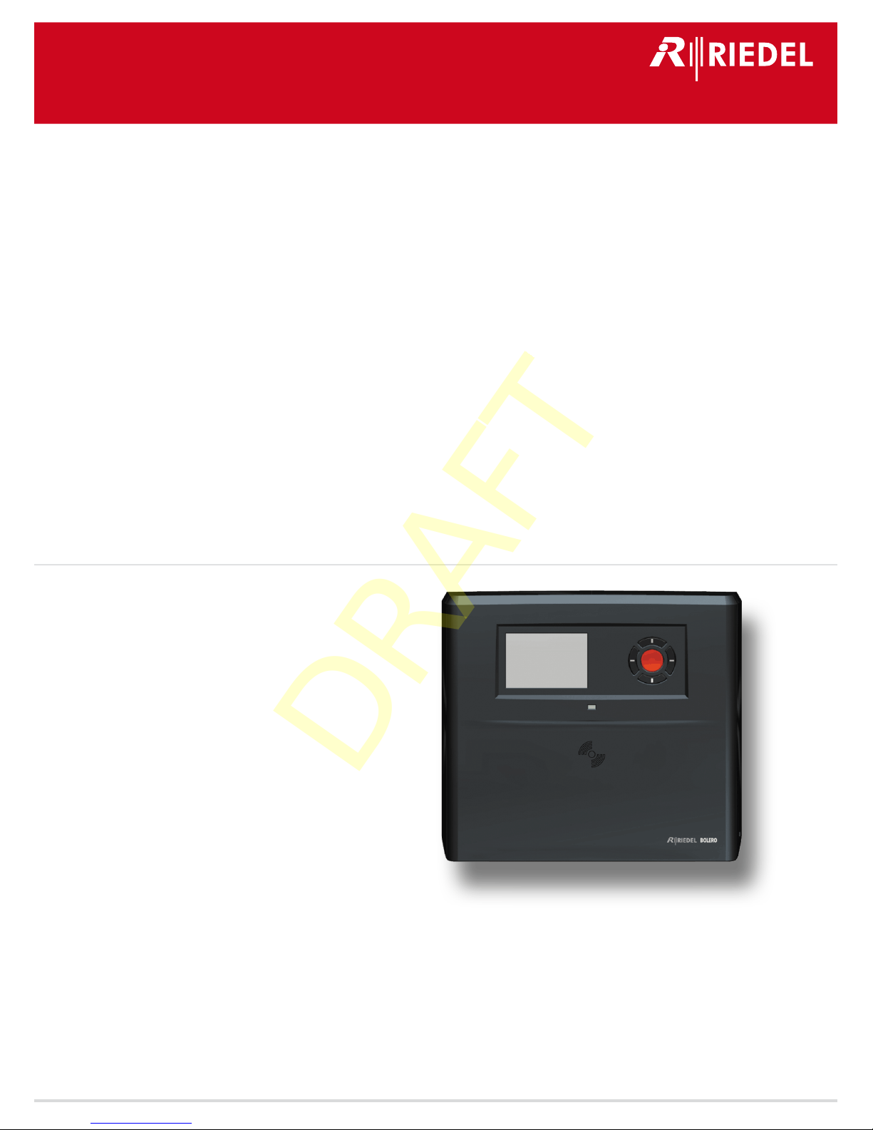
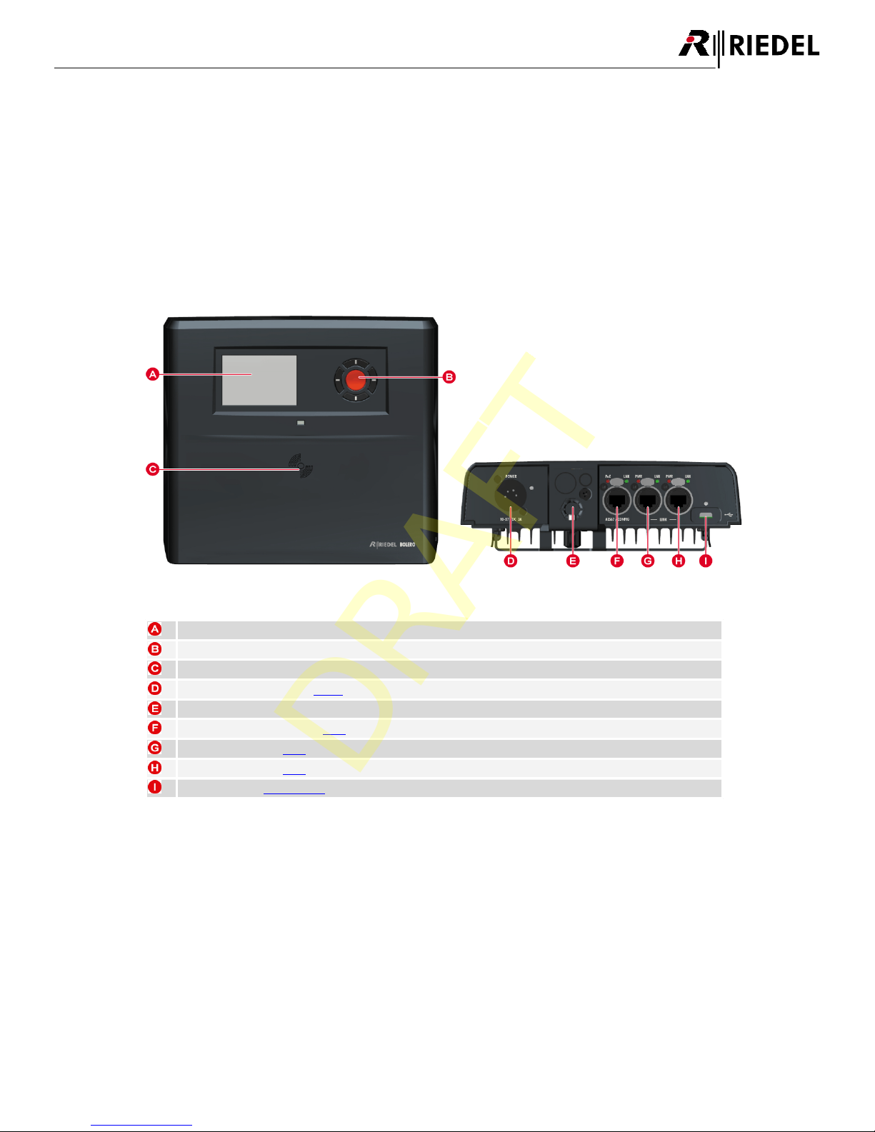
This PDF document provides detailed information about the Bolero Antenna, pin outs, mechanical and electrical data.
For further information, please refer to the Riedel Website or contact your local distributor or the Riedel headquarters
in Wuppertal.
NOTICE
This manual, as well as the software and any examples contained herein are provided “as is” and are subject to change
without notice. The content of this manual is for informational purpose only and should not be construed as a
commitment by Riedel Communications GmbH & Co. KG & Co. KG or its suppliers. Riedel Communications GmbH & Co.
KG & Co. KG gives no warranty of any kind with regard to this manual or the software, including, but not limited to, the
implied warranties of merchantability and fitness for a particular purpose. Riedel Communications GmbH & Co. KG &
Co. KG shall not be liable for any errors, inaccuracies or for incidental or consequential damages in connection with the
furnishing, performance or use of this manual, the software or the examples herein. Riedel Communications GmbH &
Co. KG & Co. KG reserves all patent, proprietary design, title and intellectual property rights contained herein, including,
but not limited to, any images, text, photographs incorporated into the manual or software.
All title and intellectual property rights in and to the content that is accessed through use of the products is the
property of the respective owner and may be protected by applicable copyright or other intellectual property laws and
treaties.
03-301HB01EG-A00
Bolero Antenna Quick Start Guide
© April 2017 Copyright Riedel Communications GmbH & Co. KG. All rights reserved.
Reproduction, adaptation, or translation of this manual in whole or in part is prohibited without prior written
permission of Riedel Communications GmbH & Co. KG, except as allowed under the copyright laws.
All other trademarks are the property of their respective owner.
DRAFT

5
Bolero Antenna Quick Start Guide A00
1.1 Information
Symbols
The following tables are used to indicate hazards and provide cautionary information in relation to the
handling and use of the equipment.
Danger
!
Indicates an imminently hazardous situation which, if not avoided, will result in death or
serious injury.
The highlighted line indicates the activity to prevent the danger.
Warning
!
Indicates a potentially hazardous situation which, if not avoided, could result in death or
serious injury.
The highlighted line indicates the activity to prevent the danger.
Caution
!
Indicates a potentially hazardous situation which, if not avoided, may result in minor or
moderate injury. It may also be used to alert against unsafe practices.
The highlighted line indicates the activity to prevent the danger.
This text is for generally information. It indicates the activity for ease of work or for better
understanding.
Service
·All service has to be undertaken ONLY by qualified service personnel.
·There are no user serviceable parts inside the devices.
·Do not plug in, turn in or attempt to operate an obviously damaged device.
·Never attempt to modify the equipment components for any reason.
Caution
!
All adjustments have been done at the factory before the shipment of the devices.
No maintenance is required and no user serviceable parts are inside the module.
DRAFT

6
Bolero Antenna Quick Start Guide A00
Voltage
·The power cable should only be connected to a correctly grounded source.
·Do not use any adapters.
·Never bypass a ground contact.
Danger
!
To reduce the risk of electric shock do not remove cover or expose the products to
rain or moisture.
Warning
!
Laite on liitettävä suojakoskettimilla varustettuun pistorasiaan.
Apparatet må tilkoples jordet stikkontakt.
Apparaten skall anslutas till jordat uttag.
Environment
·Never place the devices in an area of high dust particles or humidity.
·Never expose the device to any liquids.
·If the devices have been exposed to a cold environment and transferred to a warm environment,
condensation may form inside the housing. Wait at least 2 hours before applying any power to the
devices.
Declaration of Conformity
The devices conforms to the EU guidelines
EMV (EMC) 2014/30/EU
NSR (LVD) 2014/35/EU
RTTE (RED) 2014/53/EU
as attested by the CE mark.
FCC IDs:
·YFJANT101019 (Bolero DECT Antenna / BL-ANT-1010-19)
·YFJBPK100619 (Bolero Wireless Beltpack / BL-BPK-1006-19)
Industry Canada ICs:
·8706A-ANT101019 (Bolero DECT Antenna / BL-ANT-1010-19)
·8706A-BPK100619 (Bolero Wireless Beltpack / BL-BPK-1006-19)
Standards:
·EN 300 328 V1.9.1 / ETSI EN 300 328 V2.0.20
·EN 300 330 V1.8.1 / ETSI EN 300 330V2.1.0
·EN 301 406 V2.2.1
·EN 301 489-1/-3/-6/-17, EN 55022, EN 55024
·IEC/EN 60950-1/-22
·ARIB STD-T66
·ARIB STD-T101
DRAFT

7
Bolero Antenna Quick Start Guide A00
Disposal
Disposal of old Electrical & Electric Equipment (Applicable throughout the European Union and other
European countries with separate collection programs)
This symbol, found on your product or on its packaging, indicates that this product should
not be treated as household waste when you wish to dispose of it. Instead, it should be
handed over to an applicable collection point for the recycling of electrical and electronic
equipment. By ensuring this product is disposed of correctly, you will help prevent
potential negative consequences to the environment and human health, which could
otherwise be caused by inappropriate disposal of this product. The recycling of materials
will help to conserve natural resources. For more detailed information about the recycling
of this product please contact your local city office.
DRAFT

8
Bolero Antenna Quick Start Guide A00
1.2 About Bolero
Bolero Wireless Intercom
The Riedel Bolero Wireless Intercom system is a digital, easy to use full-duplex communications solution for broadcast,
security, industrial and theater applications as well as for sports and cultural events.
Bolero takes a completely new approach to wireless communications, pushing it beyond the limits of existing wireless
intercom solutions.
Riedel's Bolero Wireless Intercom solution utilizes the benefits of the Digital Enhanced Cordless Telecommunications
(DECT) standard’s base layer. This provides a license-free, cellular architecture with seamless hand-over between cells,
allowing each Bolero Wireless Beltpack to continuously monitor and automatically select the best connection to the
Antenna. The audio transmission takes place directly via the antennas. There is no need for additional devices.
Light and powerful custom lithium rechargeable battery packs are used for the Beltpack and the Antenna to provide
UPS power. Battery packs are able to charge inside the Beltpack, the Antenna as well as separately in the charger.
What is Bolero?
·Digital Wireless Intercom System
·based on the DECT standard
Riedel Bolero - Key Features
·Wireless Partyline and point-to-point
communications
·4 Wireless Partylines
·Cellular architecture with seamless hand-over
·Up to10 individually addressable Wireless Beltpacks
can be connected at the same time at one Antenna
·Excellent audio quality via VoIP-over-DECT
technology (license-free worldwide)
·Connection of antennas via existing Ethernet
infrastructure (PoE)
·No interference with radio microphones, In Ear
Monitoring (IEM) or other UHF systems
DRAFT

9
Bolero Antenna Quick Start Guide A00
2Bolero Antenna
The Bolero Antennas are connected together via Ethernet, allowing the use of existing standard structured cabling and
providing a wide area between the Antennas. The Antenna is powered via Power-over-Ethernet (PoE), simplifying
installations by eliminating local power supplies. Light and powerful custom lithium rechargeable battery packs are
used in the Antenna to provide UPS power. The battery packs are charged during normal operation. The Bolero Cell
Antenna has a range of approx. 330 feet (100 meters) under line-of-sight conditions or approx.165 feet (50 meters)
indoors.
2.1 Operating Elements
Figure 1: Antenna (front, bottom)
Display
Navigation buttons (cursor and menu button)
NFC contact point
Power supply connector (XLR-4)
Mounting element (TV spigot, 3/8 & 5/8 microphone stand mounting)
AES67 Network connector (RJ45)
ULLI*1 connector 1 (RJ45)
ULLI*1 connector 2 (RJ45)
USB connector (USB Type-C)
*1 (Ultra Low Latency Interface)
DRAFT

10
Bolero Antenna Quick Start Guide A00
XLR-4 (male)
1
23
4
Pin
Power Supply
1
-PWR
2
Chassis
3
1W
4
+PWR (10...57 VDC / 3 A)
Figure 2: XLR-4 male
RJ45
1 8
Pin
AES67/Config
ULLI (LINK 1+2)
1
+PWR
+PWR
2
+PWR
+PWR
3
-PWR
-PWR
4
+PWR
+PWR
5
+PWR
+PWR
6
-PWR
-PWR
7
-PWR
-PWR
8
-PWR
-PWR
Figure 3: RJ45
USB Typ-C
A1 A12
B12 B1
Pin
Pin
1
GND
7
Dn1
2
SSTXp1
8
SBU1
3
SSTXn1
9
VBUS
4
VBUS
10
SSRXn2
5
CC1
11
SSRXp2
6
Dp1
12
GND
Abbildung 4: USB Type-C
The USB connector is used for the firmware update.
DRAFT

11
Bolero Antenna Quick Start Guide A00
2.2 Status LEDs
Figure 5: Antenna (Status LED positions front)
Status-LED
off
not powered
green
on
Antenna ready (System ok)
blinking
Locate mode
yellow
on
Antenna occupied (time slots are full)
blinking
booting
red
on
low battery level
blinking
Antenna failure
DRAFT

12
Bolero Antenna Quick Start Guide A00
Figure 6: Antenna (Status LED positions bottom)
Power-LED
off
no XLR input power
green
on
XLR input power ok
AES67-PoE-LED
off
no PoE input power
green
on
PoE input power ok
red
on
PoE input power out of range
ULLI-PWR-LEDs
off
no ULLI input power
green
on
ULLI input power ok
red
on
ULLI input power out of range
AES67-LNK-LED
off
no AES67 connection present
green
on
AES67 connection ok
red
on
AES67 connection failure
ULLI-LNK-LEDs
off
no ULLI connection present
green
on
ULLI connection ok
red
on
ULLI connection failure
USB-LED
off
no USB input power
green
on
USB input power ok
red
on
USB input power out of range
DRAFT

13
Bolero Antenna Quick Start Guide A00
2.3 Getting Started
ØAttach the power supply to the Antenna.
ØOpen the Antenna-Menu by pressing and holding (>1 sec.) the Menu key.
ØCreate a new Net (Create Net) or join an existing Net (Join Net).
The Antenna is now ready for operation.
All members can listen and talk to the members registered to the Bolero-Net.
2.4 Technical Specifications
No of Beltpacks per Antenna
10
RF Frequency Range
1.880 ... 1.930GHz (region dependant)
RF Range
Indoor (structure dependent): ~200 ... 400m
Outdoor (Free line of sight): ~300 ... 500m
Programmable Transmission
power
Yes
Beltpack Registration
1 touch NFC & over the air
Network Connection
AES67 IP
Display Type
High contrast E-ink display
Power Supply
PoE+ (802.3at, type 2, class 4, 15-30 W) or 8 ... 57 VDC
Power Consumption
13 W
Mounting points
Mic stand threaded socket 5/8” & 3/8” inside, spigot adapter with wing
screw lock, Kensington lock hole, screw hole for a safety wire mounting
Dimensions
Width
210 mm / 8.3"
Height
190 mm / 7.5"
Depth
66 mm / 2.6"
Weigth
1000g
Environmental
IP53 sealing; dust + water spray at up to 60° from vertical
Operating Environment
Temperature
-10° … +55°C
Humidity
0 % ... 90 % rel. (none condensing), Ta=40°C
DRAFT

14
Bolero Antenna Quick Start Guide A00
3 Appendix
3.1 Service
If you have any further questions, we offer comprehensive customer service options for this product including:
·Telephone Service
·Email Service
·Skype Service
·Fax Service
·Configuration Support
·Trainings
·Repair
Your primary point of contact for any service issues is your local dealer.
In addition, Riedel Customer Service in Wuppertal, Germany is also available to assist you.
Telephone: +49 (0) 202 292 9400
(Monday - Friday, 8am – 5pm, Central European Time)
Fax: +49 (0) 202 292 9419
Skype: riedel.communications.service
Or use the contact form on our website:
www.riedel.net > Company > Riedel Communications > Contact > Wuppertal (Headquarters)
For repairs, please contact your local dealer. Your dealer will be able to help process your repair as fast as possible
and/or arrange for the delivery of spare parts.
The address for repairs sent directly to Riedel Communications GmbH is:
Riedel Communications GmbH & Co. KG
- Repairs -
Uellendahler Str. 353
D-42109 Wuppertal
Germany
Please add a completed repair form to all your repairs.
The form can be found at the Riedel website:
www.riedel.net > Company > Services > Support > Contact
DRAFT

15
Bolero Antenna Quick Start Guide A00
3.2 Notes
DRAFT

16
Bolero Antenna Quick Start Guide A00
Notes
DRAFT

17
Bolero Antenna Quick Start Guide A00
Index
- A -
About Bolero 8
AES67-LNK-LED (Antenna) 12
AES67-PoE-LED (Antenna) 12
- B -
Bolero Antenna 9
- C -
CE Declaration of Conformity 5
Configuration Support 14
contact 14
- D -
Dimensions (Antenna) 13
Disposal 5
- E -
Email 14
Environment 5
- F -
Fax 14
Firmware Update 10
- G -
Getting Started (Antenna) 13
- L -
Ladebuchsen Pinbelegung 10
- N -
Notes 15
- O -
Operating Elements (Antenna) 9
Operating Environment (Antenna) 13
- P -
Power (Antenna) 13
Power-LED (Antenna) 12
Preface 4
- R -
Repair 14
RJ-45 10
- S -
Service 5, 14
Skype 14
Status LEDs (Antenna) 11
Status-LED (Antenna) 11
Symbols 5
- T -
Technical Specifications (Antenna) 13
Telephone 14
Trainings 14
- U -
ULLI-LNK-LEDs (Antenna) 12
ULLI-PWR-LEDs (Antenna) 12
USB Type-C 10
USB-LED (Antenna) 12
- V -
Ventilation 5
Voltage 5
- W -
Weight (Antenna) 13
- X -
XLR-4 männlich 10
DRAFT

www.riedel.netRiedel Communications GmbH & Co. KG |Uellendahler Str. 353 |42109 Wuppertal |Germany
DRAFT
Other manuals for Bolero
2
Table of contents
Popular Antenna manuals by other brands

Stim Wave Technologies
Stim Wave Technologies PDBT-915-2K user manual

Atlantis Land
Atlantis Land A02-ANT0801 quick start guide

JCM Technologies
JCM Technologies ACTIVA manual

Matsing
Matsing MS-MBA-3.2-H4-L4 instruction manual

Ercogener
Ercogener EG-IoT-40B1 user guide

Omega Engineering
Omega Engineering OMWT-DIPOLE-900-25 instruction sheet