Riello NetMan User manual

NetMan Sensor Interface
1Wire 4 Channel A/D converter
– User’s Manual –


INTRODUCTION............................................................................................................................................... 4
SAFETY............................................................................................................................................................. 4
TECHNICAL DATA........................................................................................................................................... 5
INPUT.............................................................................................................................................................. 5
CONNECTIONS................................................................................................................................................. 5
CABLE SPECIFICATIONS ................................................................................................................................... 6
INSTALLATION ................................................................................................................................................ 6
NETMAN PLUS JUMPER SETTINGS..................................................................................................................... 6
CONNECTION OF THE SENSORS TO THE NETMAN PLUS ...................................................................................... 7
PHISICAL INSTALLATION OF THE DEVICE ............................................................................................................ 8
SOFTWARE SETUP......................................................................................................................................... 9
IRRADIANCE SENSOR APPLICATION ........................................................................................................ 10

ENGLISH
4
INTRODUCTION
Thank you for choosing our product.
The accessories described in this manual are of the highest quality, carefully designed and
built in order to ensure excellent performance.
This manual contains detailed instructions on how to install and use the product.
It should be kept with care near the device, so that it can be consulted for information on
how to use and make the most of your device. IT SHOULD BE READ BEFORE YOU
START WORKING ON THE DEVICE.
SAFETY
This part of the manual contains SAFETY precautions that must be followed
scrupulously.
The device has been designed to operate only in closed environments. It should be
installed in rooms where there are no inflammable liquids, gas or other harmful
substances.
Take care that no water or liquids and/or foreign bodies fall into the device.
In the event of a fault and/or impaired operation of the device, do not attempt to repair it
but contact the authorized service centre.
The device must be used exclusively for the purpose for which it was designed. Any other
use is to be considered improper and as such dangerous. The manufacturer declines all
responsibility for damage caused by improper, wrong and unreasonable use.
© No part of this manual may be reproduced without the prior written permission of the
manufacturer.
The manufacturer reserves the right to modify the product described in this manual at any
time and without notice.

ENGLISH
5
TECHNICAL DATA
INPUT
This device is a 4 channel A/D converter.
Each channel has a standard input voltage range 0-10V.
This device also provides a 15V unstabilized power supply capable to source 20mA
(100mA max. if connected to an external power supply (12~18V )through the
Jack connector), allowing to supply a low power consumption transducer.
CONNECTIONS
This product has two 1-Wire RJ12 ports for daisy-chain connection (Picture 2, Picture 3,
Picture 5); a Jack connector (Picture 3) to add an external power supply and two
removable terminal blocks (Picture 1) for an easier connection of the analog channels
(Picture 4).
Picture 2 1-Wire ports
DC power
supply output
Analog inputs
Picture 1 Removable terminal blocks
Picture 3 Jack and RJ12 connectors
1. +5V
2. GND
3. Data
4. GND
5. N.C.
6. N.C.
RJ 12 plug
Picture 5 RJ12 connector
+15Vout
GND
+15Vout
GND
Power supply
output
Analog input 1
GND
Analog input 2
GND
Analog input 3
GND
Analog input 4
GND
Analog input
Connector
Picture 4 Terminal block connectors

ENGLISH
6
CABLE SPECIFICATIONS
In case it is necessary a cable longer than 5 meters, it is possible to build one following the
schematic in Picture 6 and Picture 7.
Please note that the total cable length must be less or equal than 30 meters and the
Number of devices must be less or equal than 6 (where this device counts 2).
The cable used must be shielded and only one end of the shield should be tied to
protection earth (PE).
Picture 6 netman to sensor interface
Picture 7 sensor to sensor cable
INSTALLATION
NETMAN PLUS JUMPER SETTINGS
In order to use the environmental sensors, please configure the JP6 and JP10 jumpers as
shown below. See also the NetMan plus manual for configuring the other jumpers.

ENGLISH
7
CONNECTION OF THE SENSORS TO THE NETMAN PLUS
(only for NetMan 102 plus): For proper working of the communication between
sensors and NetMan 102 plus, it is necessary to guarantee the electrical
continuity (ground connection) between the DB9 hexagonal threaded spacers
and the chassis of the UPS / Solar inverter. Before connecting the sensors is
therefore necessary:
to fix the DB9 spacers and the tooth lock washers (supplied with the
sensor) as shown on the following image
to fix the NetMan to the UPS / Solar inverter with the supplied screws
and tooth lock washers.
By means of a multimeter, check the electrical
continuity between the DB9 hexagonal threaded
spacers (see picture) and the chassis of the UPS
/ Solar inverter.

ENGLISH
8
PHISICAL INSTALLATION OF THE DEVICE
This device can be installed on a DIN (see Picture 8, Picture 9 and Picture 10) rail or wall-
mounted (Picture 11).
12
3
1. Bolt
2. Washers
3. Nut
Picture 8 assemble bolt Picture 9 lift the wings by means of a flat
screw driver
Picture 10 hang the device on a DIN rail and
screw the bolts to secure the case to the rail
Picture 11 Drill template for wall-mount (dimensions in mm)

ENGLISH
9
SOFTWARE SETUP
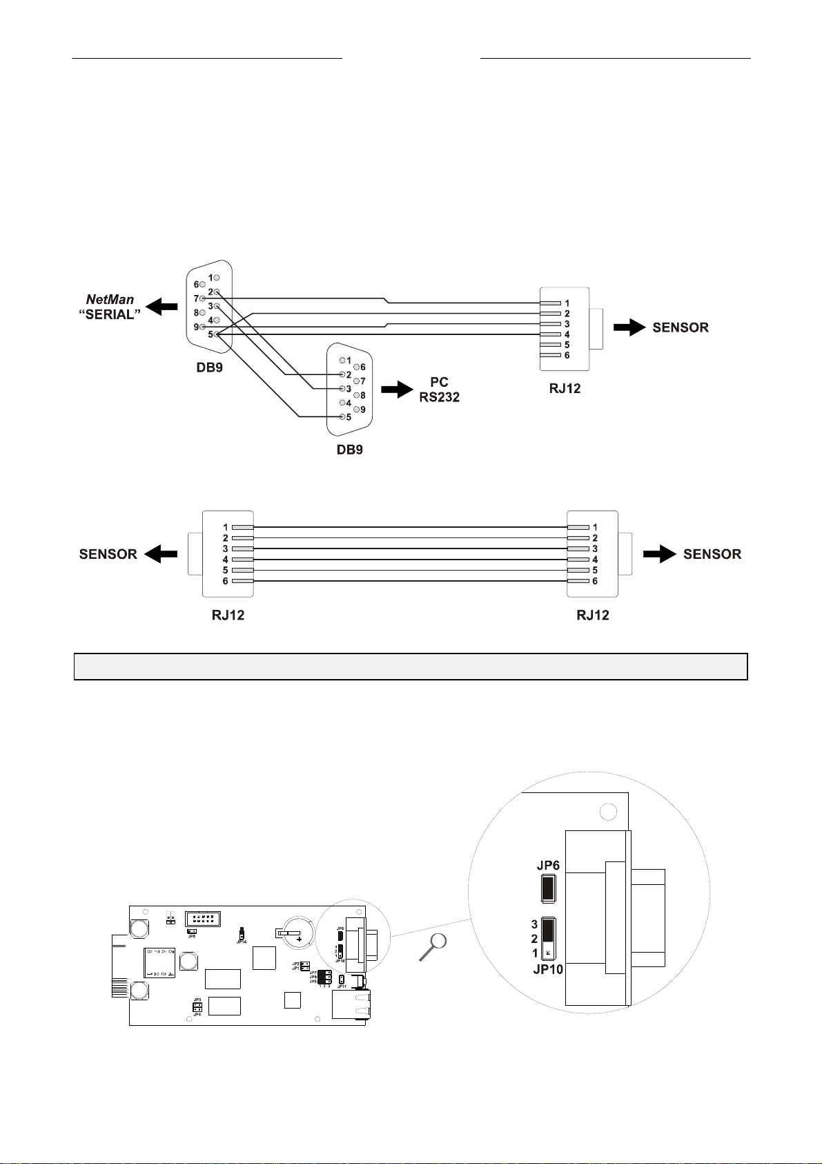
To establish the communication within the NetMan card and this product, please connect
to the NetMan trough either serial port or telnet client and enable sensors (please refer to
the NetMan user’s manual) and proceed as described in the following steps.
/------------------------/
/ PVI Network card /
/------------------------/
IP config......:
Time setting...:
PVI config.....:
Feeding config.:
Services 1.....:
Services 2.....:<--
Security.......:
Save and load..:
Press [Esc] to quit
Version S1.12p1 - Data from flash -
Communication lost
/------------------------/
/ Services 2 /
/------------------------/
WakeOnLan addr.:
WakeOnLan delay:
Activation 2...:
Sensors Config.:<--
I/O Sensors....:
Press [Esc] to quit
Version S1.12p1 - Data from flash -
Communication lost
STEP 1: Enter the “Services 2” menu STEP 2: Enter the “Sensor Config” menu
Sensors Devices
Press [C] to change sensors, [E] to exit
Sensors Devices
[1] A/D Converter (2600000013DF1E20)
+ 4 A/D Converter
[2] Dummy
Press [Y] to confirm, [N] to insert a new sensor
STEP 3: Press ‘C’ to force the NetMan to scan the 1-Wire bus
for sensors
STEP 4: 2 out of 6 channels are occupied by this device, hence a
dummy placeholder device appears with the A/D Converter.
Confirm the bus scan by pressing ‘Y’
/------------------------/
/ PVI Network card /
/------------------------/
IP config......:
Time setting...:
PVI config.....:
Feeding config.:
Services 1.....:
Services 2.....:
Security.......:
Save and load..:<--
Press [Esc] to quit
Version S1.12p1 - Data from flash -
Communication lost
/------------------------/
/ Save and load /
/------------------------/
Save changes...:<--
Revert changes.:
Load from file.:
Save to file...:
Netboot........:
Reset default..:
Press [Esc] to quit
Version S1.12p1 - Data from flash -
Communication lost
STEP 5: Go back to the main menu and enter the “Save and load
menu” STEP 6: save changes: NetMan will reboot.

ENGLISH
10
IRRADIANCE SENSOR APPLICATION
With reference to Picture 4, in order to use an irradiance and temperature sensor, please
connect the irradiance output to the “Analog Input 1” terminal; temperature to the “Analog
Input 2” terminal; GND on any of the available GND connections.
The supported input ranges for the sensor are (0 ~ 1200) W/m2and (-20 ~ +80)°C
Please tie to PE the shield of the sensor’s cable either on this device side, or on
transducer side not on both sides.
Once the setup described in the previous chapters is accomplished, the Irradiance sensor
values are available through the software SunVision (please refer to its user’s manual).


ITALIANO
13
INTRODUZIONE ............................................................................................................................................. 14
SICUREZZA.................................................................................................................................................... 14
DATI TECNICI................................................................................................................................................. 15
INGRESSO ..................................................................................................................................................... 15
CONNESSIONI................................................................................................................................................ 15
SPECIFICHE DEI CAVI...................................................................................................................................... 16
INSTALLAZIONE............................................................................................................................................ 16
IMPOSTAZIONE DEI JUMPER ............................................................................................................................ 16
CONNESSIONE DEI SENSORI ALLA SCHEDA NETMAN PLUS................................................................................ 17
INSTALLAZIONE FISICA DEL DISPOSITIVO.......................................................................................................... 18
IMPOSTAZIONI SOFTWARE......................................................................................................................... 19
APPLICAZIONE SENSORE DI IRRAGGIAMENTO ...................................................................................... 20

ITALIANO
14
INTRODUZIONE
Grazie per aver scelto il nostro prodotto.
L’accessorio descritto nel presente manuale è di alta qualità, accuratamente progettato e
costruito per garantire prestazioni eccellenti.
Questo manuale contiene istruzioni dettagliate riguardo l’installazione e l’uso del prodotto.
Dovrebbe essere conservato con cura vicino al dispositivo, così da poter essere
consultato per informazioni riguardo l’uso del prodotto e per sfruttarlo al meglio.
DOVREBBE ESSERE LETTO PRIMA DI COMINCIARE AD USARE IL PRODOTTO.
SICUREZZA
Questa parte del manuale contiene precauzioni di SICUREZZA che devono essere
adottate scrupolosamente
Il dispositivo è stato progettato per lavorare in ambiente interno. Deve essere installato in
stanze prive di liquidi o gas infiammabili o altre sostanze pericolose.
Prestare attenzione che all’interno del dispositivo non finiscano acqua o corpi estranei.
Se dovesse verificarsi un guasto o se il dispositivo presentasse un funzionamento
anomalo, non tentare la riparazione. Contattare un centro per il servizio di assistenza
tecnica.
Il dispositivo deve essere usato esclusivamente per lo scopo per cui è stato progettato.
Qualunque altro uso è da considerarsi improprio, quindi pericoloso. Il produttore declina
ogni responsabilità per danni causati dall’utilizzo improprio, sbagliato o irragionevole.
© Nessuna parte di questo manuale può essere riprodotta senza il permesso scritto del
produttore.
Il produttore si riserva il diritto di cambiare il prodotto descritto in questo manuale in
qualsiasi momento senza preavviso.

ITALIANO
15
DATI TECNICI
INGRESSO
Questo dispositivo è un convertitore A/D a 4 canali.
Ogni canale ha un intervallo standard di misura 0-10 V
Questo dispositivo fornisce anche un’alimentazione non stabilizzata a 15V capace di
fornire al massimo 20mA
(100 mA se connesso ad un alimentatore esterno (12~18V ) tramite il connettore
Jack), consentendo così di alimentare un trasduttore a basso assorbimento.
CONNESSIONI
Questo prodotto ha due porte 1-Wire RJ12 per consentire una connessione in cascata di
più dispositivi (Figura 2, Figura 3, Figura 5); un connettore Jack per l’alimentazione
esterna (Figura 3) e due morsettiere rimovibili (Figura 1) per una connessioni più semplice
degli ingressi analogici (Figura 4).
Figura 2 Porte 1-Wire
Uscita alimentazione
CC
Ingressi analogici
Figura 1 Connettori rimovibili
Figura 3 Connettori Jack e RJ12
1. +5V
2. GND
3. Data
4. GND
5. N.C.
6. N.C.
Spina RJ12
Figura 5 Connettore RJ12
+15Vout
GND
+15Vout
GND
Uscita alimentazione
Ingresso 1
GND
Ingresso 2
GND
Ingresso 3
GND
Ingresso 4
GND
Connettore
ingressi analogici
Figura 4 Connessioni morsettiere

ITALIANO
16
SPECIFICHE DEI CAVI
In caso sia necessario l’uso di un cavo più lungo di 5 metri, è possibile costruirne uno
seguendo lo schema in Figura 6 e in Figura 7
Si noti che la lunghezza totale del cavo non deve superare i 30 metri e che il numero
massimo di dispositivi in cascata è 6 (Il presente dispositivo conta per 2).
Il cavo usato deve essere schermato e solo una estremità del cavo deve essere
connessa a terra
Figura 6 cavo dalla scheda netman al “sensor interface”
Figura 7 cavo tra sensori
INSTALLAZIONE
IMPOSTAZIONE DEI JUMPER
Per usare I sensori ambientali, configurare i jumper JP6 e JP10 come mostrato di seguito.
Consultare anche il manuale della scheda NetMan plus per l’impostazione degli altri
jumper.

ITALIANO
17
CONNESSIONE DEI SENSORI ALLA SCHEDA NETMAN PLUS
(solo per NetMan 102 plus): Per un corretto funzionamento della
comunicazione tra i sensori e il NetMan 102 plus, è necessario garantire la
continuità elettrica (connessione a terra) tra le torrette di fissaggio del
connettore DB9 e la carpenteria dell’UPS / Inverter fotovoltaico. Pertanto prima
di collegare i sensori è necessario:
Fissare le torrette e le rondelle dentellate fornite in dotazione con il
sensore come illustrato nell’immagine seguente
Fissare il NetMan all’UPS / Inverter fotovoltaico tramite le viti e le
rondelle dentellate fornite in dotazione
Con l’ausilio di un multimetro, verificare la
continuità elettrica tra la torretta di fissaggio del
connettore DB9 (indicata a lato) e la carpenteria
dell’UPS / Inverter fotovoltaico

ITALIANO
18
INSTALLAZIONE FISICA DEL DISPOSITIVO
Questo dispositivo può essere installato su barra DIN (Figura 8, Figura 9, Figura 10) o
montato a muro (Figura 11).
12
3
1. Bullone
2. Rondelle
3. Dado
Figura 8 assemblare dado, rondelle e bullone Figura 9 sollevare le alette con un
cacciavite piatto
Figura 10 agganciare il dispositivo alla barra DIN,
quindi stringere i dadi
Figura 11 Maschera di foratura per il fissaggio a muro

ITALIANO
19
IMPOSTAZIONI SOFTWARE
Per stabilire la comunicazione tra la scheda NetMan e questo prodotto, collegarsi alla
scheda NetMan attraverso la sua porta seriale o telnet e abilitare I sensori (fare riferimento
al manuale della scheda NetMan), quindi procedere come descritto di seguito.
/------------------------/
/ PVI Network card /
/------------------------/
IP config......:
Time setting...:
PVI config.....:
Feeding config.:
Services 1.....:
Services 2.....:<--
Security.......:
Save and load..:
Press [Esc] to quit
Version S1.12p1 - Data from flash -
Communication lost
/------------------------/
/ Services 2 /
/------------------------/
WakeOnLan addr.:
WakeOnLan delay:
Activation 2...:
Sensors Config.:<--
I/O Sensors....:
Press [Esc] to quit
Version S1.12p1 - Data from flash -
Communication lost
1: Entrare nel menu “Services 2” 2: Entrare nel menù “Sensor Config”
Sensors Devices
Press [C] to change sensors, [E] to exit
Sensors Devices
[1] A/D Converter (2600000013DF1E20)
+ 4 A/D Converter
[2] Dummy
Press [Y] to confirm, [N] to insert a new sensor
3: Premere ‘C’ per forzare la scheda NetMan ad eseguie una
scansione del bus 1-Wire.
4 Questo sensore occupa 2 dei 6 canali disponibili, quindi
assieme all’A/D converter è visualizzato anche un elemento
fittizio “Dummy”. Confermare premendo ‘Y’
/------------------------/
/ PVI Network card /
/------------------------/
IP config......:
Time setting...:
PVI config.....:
Feeding config.:
Services 1.....:
Services 2.....:
Security.......:
Save and load..:<--
Press [Esc] to quit
Version S1.12p1 - Data from flash -
Communication lost
/------------------------/
/ Save and load /
/------------------------/
Save changes...:<--
Revert changes.:
Load from file.:
Save to file...:
Netboot........:
Reset default..:
Press [Esc] to quit
Version S1.12p1 - Data from flash -
Communication lost
5 _Toranre al menu principale 6: Salvare I cambiamenti: la scheda NetMan si riavvia.

ITALIANO
20
APPLICAZIONE SENSORE DI IRRAGGIAMENTO
Con riferimento alla Figura 4, per usare un sensore di irraggiamento e temperature,
collegare l’uscita irraggiamento all’ingresso 1; il sensore di temperatura all’ingresso 2; la
massa a qualunque delle connessioni GND disponibili.
Gli intervalli di misura suportati sono (0 ~ 1200) W/m2 e (-20 ~ +80)°C
Collegare a terra lo schermo del cavo del sensore dalla parte di questo dispositivo o
dalla parte del trasduttore, non da entrambe le parti.
Una volta completate le operazioni descritte nei precedenti capitoli, i valori misurati sono
resi disponibili attraverso il software SunVision (fare riferimento al manuale utente del
software).
Table of contents
Languages:
Popular Accessories manuals by other brands

Thermos
Thermos SOFT COOLER WITH ANTIMICROBIAL FLEX-A-GUARD... Care and use guide

Halma
Halma BEA LZR-WIDESCAN Mechanical installation

Carefree
Carefree PIONEER PATIO installation manual

Zamel
Zamel Sundi GLASSO manual

Strend Pro
Strend Pro GW8005 instruction manual

Hamilton Beach
Hamilton Beach 74378R use & care