8
RESIDENCE
Twin pipes with Ø 80 pipework (Ø50 - Ø60 - Ø80) (Fig. 17)
Thanks to the boiler characteristics, a Ø80 ue gas exhaust pipe can be connected to the Ø50
- Ø60 - Ø80 piping ranges.
b
For the pipe, you are advised to make a project calculation in order to respect the rele-
vant regulations in force.
The table shows the standard congurations allowed.
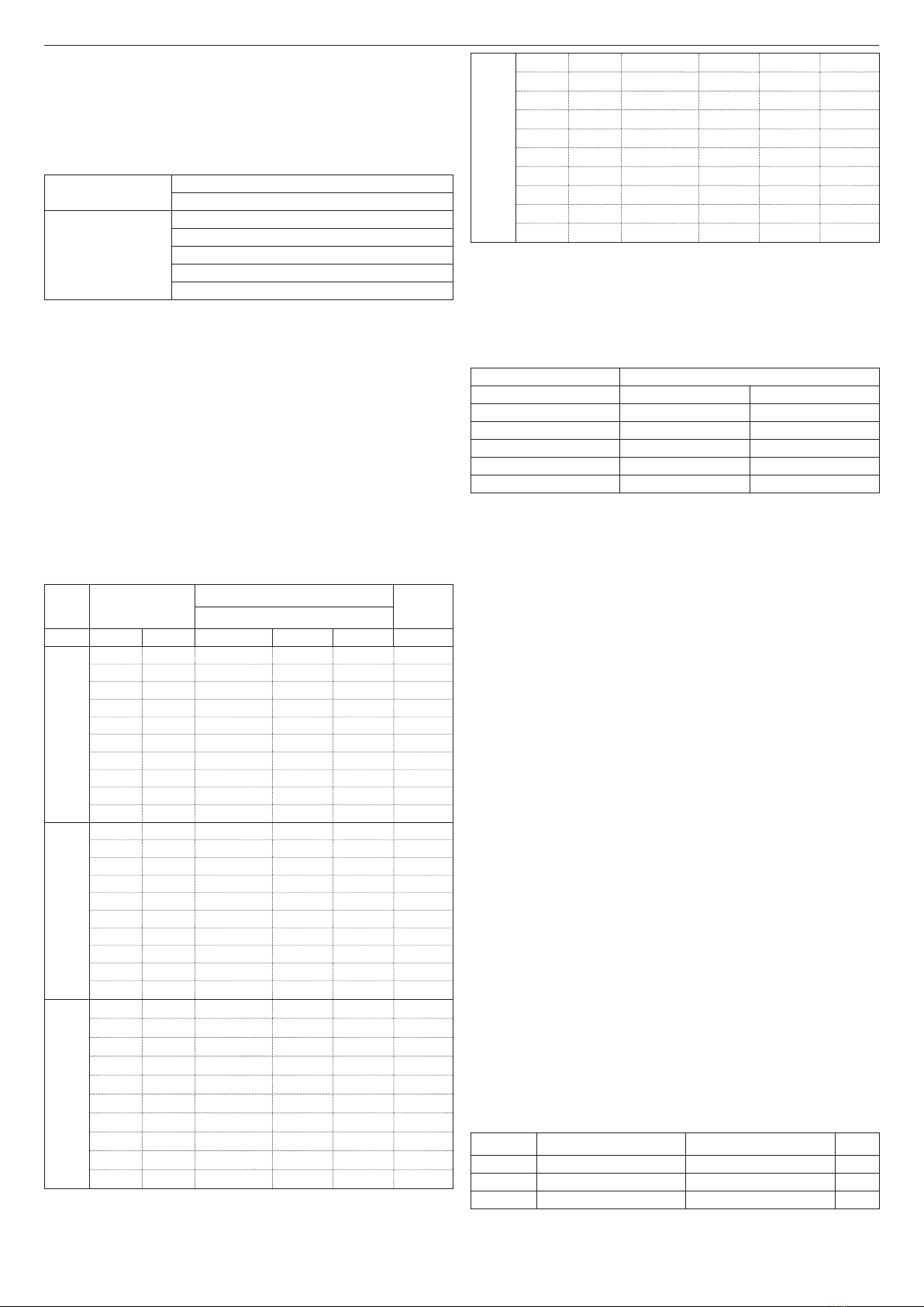
Table of standard pipe conguration (*)
Air suction 1 Bend 90° Ø 80
4.5m pipe Ø80
Flue gas discharge
1 Bend 90° Ø 80
4.5m pipe Ø80
Reduction from Ø80 to Ø50 from Ø80 to Ø60
Flue base bend 90°, Ø50 or Ø60 or Ø80
For ducting pipe lengths see table
(*) Use ue gas system accessories made of plastic (PP) for condensing boilers: Ø50 and Ø80
class H1 and Ø60 class P1.
The boilers are factory set to:
25 KIS: 6,200 r.p.m. in heating mode and 7,600 in domestic hot water mode and the maximum
attainable length is 5m for the Ø 50 pipe, 18 m for the Ø 60 pipe and 98 m for the Ø 80 pipe.
30 KIS: 5,800 rpm in heating mode and 6,900 in domestic hot water mode, and the maximum
length that can be reached is 2m for the Ø50 and 11 m for the Ø60 pipe and 53 m for the Ø80
pipe.
35 KIS: 6,900 rpm in heating mode and 7,800 in domestic hot water mode, and the maximum
length that can be reached is 2m for the Ø50 pipe and 11 m for the Ø60 pipe and 57 m for the
Ø80 pipe.
40 KIS: 6,900 rpm in heating mode and 9,100 in domestic hot water mode, and the maximum
length that can be reached is 7m for Ø60 pipe and 42m for Ø80 pipe (not applicable for Ø50
pipe).
Should greater lengths be required, compensate the pressure drop with an increase in the
r.p.m.of the fan, as shown in the adjustments table, to provide the rated heat input.
b
The minimum calibration should not be modied.
Table of adjustments
Fan rotations
r.p.m.
Pipework ducts ΔP at boiler
outlet
Maximum length [m]
CH DHW Ø 50 Ø 60 Ø 80 Pa
25 KIS
6,200 7,600 5 18 98 174
6,300 7,700 7 (*) 23 (*) 125 (*) 213
6,400 7,800 9 (*) 28 (*) 153 (*) 253
6,500 7,900 11 (*) 33 (*) 181 (*) 292
6,600 8,000 13 (*) 38 (*) 208 (*) 332
6,700 8,100 15 (*) 43 (*) 236 (*) 371
6,800 8,200 17 (*) 48 (*) 263 (*) 410
6,900 8,300 19 (*) 53 (*) 291 (*) 450
7,000 8,400 22 (*) 58 (*) 319 (*) 489
7,100 8,500 24 (*) 63 (*) 346 (*) 528
30 KIS
5,800 6,900 2 11 53 150
5,900 7,000 4 15 73 189
6,000 7,100 5 (*) 19 (*) 93 (*) 229
6,100 7,200 7 (*) 24 (*) 113 (*) 268
6,200 7,300 9 (*) 28 (*) 133 (*) 308
6,300 7,400 10 (*) 32 (*) 153 (*) 347
6,400 7,500 12 (*) 36 (*) 173 (*) 386
6,500 7,600 14 (*) 40 (*) 193 (*) 426
6,600 7,700 16 (*) 44 (*) 214 (*) 465
6,700 7,800 17 (*) 49 (*) 234 (*) 504
35 KIS
6,900 7,800 2 11 57 190
7,000 7,900 3 (*) 15 (*) 75 (*) 229
7,100 8,000 4 (*) 19 (*) 93 (*) 269
7,200 8,100 6 (*) 22 (*) 112 (*) 308
7,300 8,200 7 (*) 26 (*) 130 (*) 348
7,400 8,300 9 (*) 30 (*) 148 (*) 387
7,500 8,400 10 (*) 33 (*) 166 (*) 426
7,600 8,500 12 (*) 37 (*) 184 (*) 466
7,700 8,600 13 (*) 40 (*) 202 (*) 505
7,800 8,700 15 (*) 44 (*) 220 (*) 544
40 KIS
6,900 9,100 not applicable 7 42 196
7,000 9,200 not applicable (*) 10 (*) 60 (*) 235
7,100 9,300 1 (*) 13 (*) 78 (*) 275
7,200 9,400 3 (*) 16 (*) 96 (*) 314
7,300 9,500 4 (*) 19 (*) 114 (*) 354
7,400 9,600 5 (*) 23 (*) 138 (*) 393
7,500 9,700 7 (*) 26 (*) 156 (*) 432
7,600 9,800 8 (*) 29 (*) 174 (*) 472
7,700 9,900 9 (*) 32 (*) 192 (*) 511
7,800 10,000 10 (*) 35 (*) 210 (*) 550
(*) Maximum length that can be installed ONLY with class H1 discharge pipes.
The Ø50 or Ø60 or Ø80 congurations contain Lab test data. In the event of installations that
differ from the indications in the “standard congurations” and “adjustments” tables, refer to the
equivalent linear lengths below.
b
In any case, the maximum lengths declared in the booklet are guaranteed, and it is
essential not to exceed them.
COMPONENT Linear equivalent in metres Ø80 (m)
Ø 50 Ø 60
Bend 45° 12.3 5
Bend 90° 19.6 8
Extension 0.5m 6.1 2.5
Extension 1.0m 13.5 5.5
Extension 2.0m 29.5 12
3.16 Installation on collective ues in positive pressure (g 18)
The collective ue is a ue gas exhaust system suitable for collecting and expelling the combu-
stion products of several appliances installed on several oors of a building.
The positive pressure collective ues can only be used for type C condensing appliances. The-
refore the B53P/B23P conguration is forbidden. The installation of boilers under collective pres-
sure ues is allowed exclusively in G20.
The boiler is sized to operate correctly up to a maximum internal pressure of the ue no higher
than the value of 25 Pa. Check that the fan speed corresponds to what is shown in the table
"technical data".
Make sure that the air intake and exhaust pipes of the combustion products are watertight.
WARNINGS:
b
The appliances connected to a collective pipe must all be of the same type and have
equivalent combustion characteristics.
b
The number of devices connected to a positive pressure collective pipe is dened by
the ue designer.
The boiler is designed to be connected to a collective ue sized to operate in conditions where
the static pressure of the collective ue pipe can exceed the static pressure of the collective air
duct of 25 Pa in the condition in which n-1 boilers work at maximum rated heat input and 1 boiler
at the minimum rated heat input allowed by the controls.
b
The minimum permissible pressure difference between the ue gas outlet and the com-
bustion air inlet is -200 Pa (including - 100 Pa of wind pressure).
For both types of exhaust, further accessories are available (curves, extensions, terminals, etc.)
which make possible the ue gas exhaust congurations foreseen in the boiler booklet.
b
The pipes must be installed in such a way as to avoid condensation sticking which would
prevent the correct evacuation of the combustion products.
b
A data plate must be present at the connection point with the collective ue pipe. The
plate must include at least the following information:
-the collective ue is sized for boilers C(10) type
-the maximum permissible mass ow of the combustion products in kg/h
-the dimensions of the connection to the common pipes
-a warning concerning the openings for the air outlet and the entry of the combustion
products of the collective pressure pipe; these openings must be closed and their
tightness must be checked when the boiler is disconnected
-the name of the manufacturer of the collective smoke pipe or its identication symbol.
b
See applicable legislation for the discharge of the combustion products as well as local
regulations.
b
The ue gas pipe must be suitably selected based on the parameters shown below.
maximum length minimum length UM
ø 60-100 4,5 0,5 m
ø 80 4,5 0,5 m
ø 80/125 4,5 0,5 m