Riello K160240PB12T User manual

20 - 40 batteries
20 - 40 batterie
MODELS:
K160240PB12T
K160240PL62T
K160240PN12T
K160240PL72T
K160240VN12T
-User’s manual -
-Manuale d’uso -
BATTERY
BOX


- ENGLISH -
3
SAFETY
ATTENTION: THIS BATTERY CABINET CAN ONLY BE CONNECTED TO A SINGLE
UNINTERRUPTIBLE POWER SUPPLY (UPS). THE UPS SHALL HAVE THE SAME NOMINAL
VOLTAGE AS THE BATTERY (SEE THE DATA PLATE)
Before carrying out any work on the cabinet, make sure that the battery is completely disconnected from
the UPS and other equipment
Fully switch off the UPS before connecting the battery cabinet
Do not switch on or install the battery cabinet if any loss of battery acid is noted.
The battery cabinet presents a high risk of electrical shock and high short circuit current.
Installation and maintenance operations must only be performed by qualified, trained personnel.
Carefully follow the instructions below for installing and maintaining the battery cabinet:
Use insulated equipment.
Wear safety goggles, footwear and rubber gloves.
Observe polarities.
Remove metal objects (watches, bracelets, etc.).
Be careful not to touch the battery terminals.
If necessary, replace fuses only with same type.
Battery replacement must be performed by qualified personnel. When disposing of replaced items, you
must deliver to the appropriate centres for recycling (batteries are classified as "toxic waste").
Do not throw batteries in a fire as they can explode.
Do not attempt to open the batteries as no maintenance is required. The electrolyte is harmful to the
skin and eyes and also toxic and therefore harmful if inhaled or ingested.
Do not place liquids or other foreign bodies in the battery cabinet
The battery cabinet must be grounded

- ENGLISH -
4
INTRODUCTION
Thank you for choosing our product.
Our company is specialised in the development and production of uninterruptible power supplies (UPSs).
This manual contains detailed instructions for using and installing a BATTERY BOX for a UPS.
This manual must be stored in a safe place near the BATTERY BOX and CONSULTED BEFORE
DEVICE USE for proper usage instructions as well as maximum performance from the device itself.
ENVIRONMENTAL PROTECTION
During the development of its products, the company uses extensive resources with regards to all
environmental aspects.
All our products pursue the objective defined in the environmental management system developed by the
company in compliance with standards in force.
No hazardous materials such as CFC, HCFC or asbestos are used in this product.
When evaluating packaging, the choice of material has been made favouring recyclable materials.
For correct disposal, please separate and identify the type of material of which the packaging is made in the
table below. Dispose of all material in compliance with standards in force in the country in which the product
is used.
DESCRIPTION
MATERIAL
Pallet
Heat-treated pine
Packaging corner
Stratocell/cardboard
Box
Cardboard
Adhesive pad
Stratocell
Protective bag
HD Polyethylene
DISPOSING OF THE PRODUCT
The BATTERY BOX contains internal material that (in case of dismiss / disposal) are considered TOXIC and
HAZARDOUS WASTE, such as electronic circuit boards and batteries. Treat these materials according to
the laws applicable referring to qualified service personnel. Their proper disposal contributes to respect the
environment and human health.
© The reproduction of any part of this manual, even in part, is prohibited unless authorised by the Manufacturer.
The manufacturer reserves the right to change the product described at any time without prior notice for improvement purposes.

- ENGLISH -
5
CONTENTS
BATTERY CABINET STORAGE ............................................................................................................................. 6
PRELIMINARY OPERATIONS............................................................................................................................... 6
BATTERY CABINET HANDLING ........................................................................................................................... 6
BATTERY CABINET POSITIONING ....................................................................................................................... 7
BATTERY CABINET STRUCTURE.......................................................................................................................... 7
INSTALLATION AND BATTERY CONNECTION..................................................................................................... 7
SINGLE UNIT ASSEMBLY INSTRUCTIONS ........................................................................................................... 8
BATTERY ASSEMBLY ACCESSORY..................................................................................................................... 14
BATTERY CABINET - UPS INTERCONNECTIONS................................................................................................ 15
START-UP PROCEDURE .................................................................................................................................... 16
TECHNICAL FEATURES ..................................................................................................................................... 17

- ENGLISH -
6
BATTERY CABINET STORAGE
The storage site must comply with instructions contained in the “Technical features”chapter.
The batteries contained in the cabinet are subject to self-discharge. Whenever the battery cabinet is stored
and not installed immediately, take note of the date printed on the packing plate of the battery charger and
recharge by that date.
To recharge batteries, simply plug the battery cabinet in to a NORMAL OPERATION UPS for at least 24
hours.
For longer storage periods, contact technical assistance.
PRELIMINARY OPERATIONS
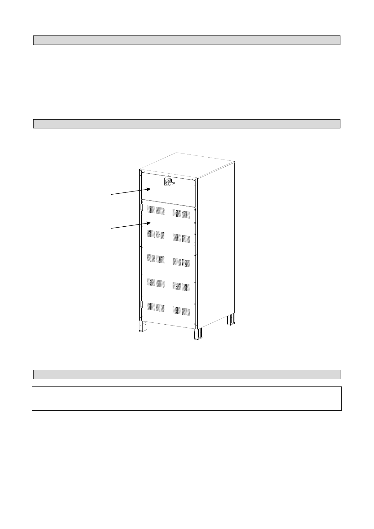
CHECKING PACKAGING AND REMOVAL
Upon receipt of the battery cabinet, ensure that packaging has not been damaged during transport. In
particular, check that none of the two anti-shock devices set in the packaging have become red. If any
are red, follow instructions contained on the packaging.
The battery cabinet should be handled with care. Any shocks or falls can cause damage.
Remove packaging carefully to avoid scratching equipment.
Operate as follows to remove packaging:
oCut straps
oCarefully remove from the cardboard packaging
oUnscrew the stops before removing the cabinet from the pallet
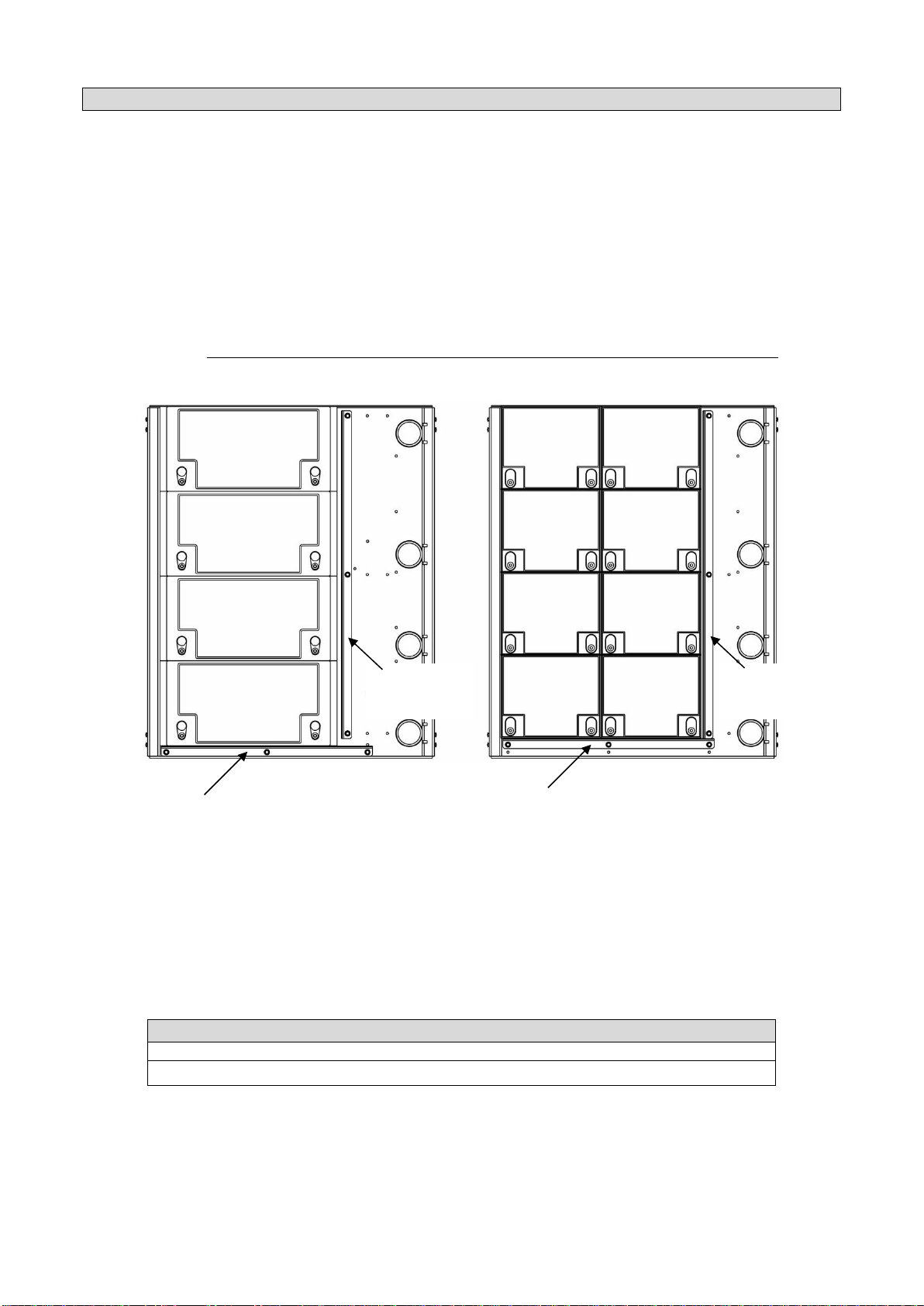
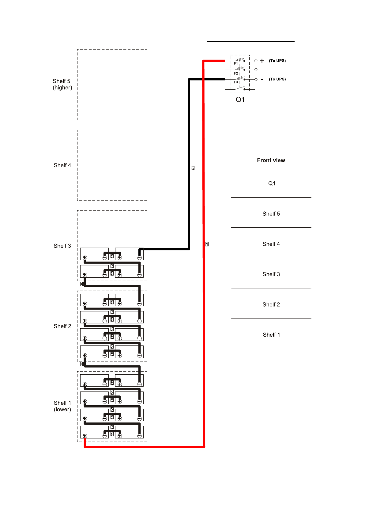
The battery cabinet, complete with assembled batteries, comes supplied with: warranty, user's manual,
2x 125A gS NH00 or 2x 63A gS NH000 fuses (20 batteries version); 3x 125A gS NH00 or 3x 63A gS
NH000 fuses (40 batteries version), fuse extraction handle.
Included in supply of the empty battery cabinet: warranty, user's manual, numbered cables (internal
wiring), fuses, fuse extraction handle, battery assembly accessory.
BATTERY CABINET HANDLING
Two cases are possible regarding cabinet handling:
1) Empty battery cabinet
2) Battery cabinet with pre-mounted internal batteries. In this case, the battery cabinet must be
handled with all its panels (side, front, rear and internal) fully tightened.
Handling (both before and after removing from packaging) must be performed with a fork lift equipped as
shown in Fig. 1.
HANDLING WITH PACKAGING
REMOVING FROM PALLET
Procedure to follow to move the still packaged
BATTERY BOX
Procedure to follow to remove from the pallet after
having removed packaging
Fig. 1

- ENGLISH -
7
BATTERY CABINET POSITIONING
When positioning the empty or full battery cabinet, keep in mind that:
A clear space of approximately 1m should be left in front of the cabinet to allow for battery assembly
and maintenance operations.
A clear space of about 20cm must be left behind the cabinet for proper cabinet ventilation.
No objects should rest on the upper part of the cabinet.
Ensure that flooring is flat and able to sustain the weight of the cabinet with batteries inside.
Necessary air exchange with the external environment must be provided for at the installation site.
BATTERY CABINET STRUCTURE
The battery cabinet, without door, comes in as per Fig. 2.
Fig. 2
INSTALLATION AND BATTERY CONNECTION
WARNING:
ALL OPERATIONS DESCRIBED BELOW INVOLVE RISK OF ELECTRIC SHOCK
CAREFULLY FOLLOW THE INSTRUCTIONS OUTLINED IN THE "SAFETY" CHAPTER
There are two possible options:
1) Battery cabinet with pre-mounted batteries
Go directly to the “Battery cabinet - UPS interconnections”chapter
2) Empty battery cabinet
In this case, insert the batteries and connect them as described in the “Single unit assembly instructions”
chapter.
A
B

- ENGLISH -
8
SINGLE UNIT ASSEMBLY INSTRUCTIONS
Follow the instructions below to assemble batteries/single units:
Open and remove the front door to facilitate handling
Remove the two internal "A" and "B" panels, see Fig. 2.
Remove the left and right side panels to facilitate battery installation and connection. THE REAR PANEL
OF THE BATTERY CABINET MUST NEVER BE REMOVED.
Remove the front locking brackets by the various shelves. Position the batteries on each shelf as per Fig.
3. Use the provided tool to facilitate battery insertion on the shelves (see chapter “Battery assembly
accessory”).
Reposition all front locking brackets.
Connect the batteries and switch with the supplied cables as per Fig. 4, Fig. 5 or Fig. 6 (20 batteries
version) or as per Fig. 7 or Fig. 8 (40 batteries version) complying with cable numbering.
ATTENTION: the supplied clear plastic guards must be mounted on the Q1 battery cabinet switch
65Ah 40Ah / 40+40Ah
Fig. 3
Assemble the two 125A NH00 fuses (or the two 63A NH000 fuses) F1 - F3 using the supplied handle (20
batteries) (see Fig. 4, Fig. 5 and Fig. 6).
Assemble the three 125A NH00 fuses (or the three 63 NH000 fuses) F1 - F2 - F3 using the supplied
handle (40 batteries) (see Fig. 7 and Fig. 8).
The wiring nuts and bolts must be tightened as per the table below
Tightening torque
Battery terminals 5 - 7 Nm
Switch terminals 14 Nm
Front locking
bracket
Side locking
bracket
Front locking
bracket
Side locking
bracket

- ENGLISH -
9
WIRING DIAGRAM: 20 BATTERIES 40Ah WITH POSITIVE POLE TO THE RIGHT
Fig. 4

- ENGLISH -
10
WIRING DIAGRAM: 20 BATTERIES 40Ah WITH POSITIVE POLE TO THE LEFT
Fig. 5

- ENGLISH -
11
WIRING DIAGRAM: 20 BATTERIES 65Ah WITH POSITIVE POLE TO THE RIGHT
Fig. 6

- ENGLISH -
12
WIRING DIAGRAM: 40 BATTERIES WITH POSITIVE POLE TO THE RIGHT
Fig. 7

- ENGLISH -
13
WIRING DIAGRAM: 40 BATTERIES WITH POSITIVE POLE TO THE LEFT
Fig. 8

- ENGLISH -
14
BATTERY ASSEMBLY ACCESSORY
The battery assembly accessory is fastened to the front part of the battery box as shown in Fig. 9 and Fig.
10. Partially screw in 2 M6x10 trefoil screws in the holes on the relative shelf, hook the accessory and finish
tightening the M6x10 trefoil screws.
After having mounted the batteries, remove the accessory and fully remove the M6x10 trefoil screws.
Fig. 9
Fig. 10

- ENGLISH -
15
BATTERY CABINET - UPS INTERCONNECTIONS
ATTENTION: before making connections, make sure that the UPS is completely switched off and that there
is no dangerous voltage on the UPS connection terminals.
Check that the battery switch Q1 is open
Open and remove the front door to facilitate handling
Remove the two internal "A" and "B" panels, see Fig. 2.
Connect wires (connection cables not supplied) from the battery cabinet to the UPS terminals (see
Fig. 11).
Connect as follows:
1. PE ground connection (yellow-green wire) to be connected first
2. “+”and “-“pole connections
Fig. 11
For dimensions of connection cables between the battery cabinet and UPS, refer to the UPS manual.
Q1

- ENGLISH -
16
Block connection cables inside the battery cabinet, using a clamp inserted in the holes made during
construction, see Fig. 12. Be careful not to scratch the cable insulation.
Fig. 12
START-UP PROCEDURE
Checks to be made on the battery cabinet
Check grounding connection (PE).
Check that the battery switch (Q1) is open.
Check battery cabinet and UPS connections to poles “+”and “-“.
Verify the battery voltages are within the range +235 ~ +270Vdc probing the points listed in the following
table on Q1 switch with a multimeter, according to the Fig. 11 image.
Product
(+) Lead
(-) Lead
20 batteries version
1
5
40 batteries version
1
7
3
5
Reposition the previously removed side panels.
Switch on the UPS, leaving the battery cabinet switch (Q1) open.
When the UPS is running (after 2 minutes), check on the battery cabinet that:
- Between bars (-) and (+)Fig. 11: voltage is within the range of 235 - 280Vdc.
Reposition previously removed internal panels A and B, see Fig. 2.
Replace the door.
If the checks and controls listed above are positive, you can close the battery cabinet switch (Q1).

- ENGLISH -
17
TECHNICAL FEATURES
K160240PB12T
BATTERY
Nominal voltage
[Vdc]
240
Nominal Ah
[Ah]
40
N° batteries / V / Ah
20 / 12 / 40
Sealed lead
OTHER DATA
Recommended operating
temperature
[°C]
0 –25
Storage temperature
[°C]
0 –40
Humidity
< 95% without condensation
Fuse type
125A gS 690V NH00
Degree of protection
IP20
Dimensions H x L x D
[mm]
1600 x 650 x 750
Weight with batteries
[Kg]
440
Weight without batteries
[Kg]
160
K160240PL62T
BATTERY
Nominal voltage
[Vdc]
240
Nominal Ah
[Ah]
65
N° batteries / V / Ah
20 / 12 / 65
Sealed lead
OTHER DATA
Recommended operating
temperature
[°C]
0 –25
Storage temperature
[°C]
0 –40
Humidity
< 95% without condensation
Fuse type
63A gS 690V NH000
Degree of protection
IP20
Dimensions H x L x D
[mm]
1600 x 650 x 750
Weight with batteries
[Kg]
570
Weight without batteries
[Kg]
160

- ENGLISH -
18
K160240PN12T
BATTERY
Nominal voltage
[Vdc]
240
Nominal Ah
[Ah]
40+40
N° batteries / V / Ah
40 / 12 / 40
Sealed lead
OTHER DATA
Recommended operating
temperature
[°C]
0 –25
Storage temperature
[°C]
0 –40
Humidity
< 95% without condensation
Fuse type
125A gS 690V NH00
Degree of protection
IP20
Dimensions H x L x D
[mm]
1600 x 650 x 750
Weight with batteries
[Kg]
730
Weight without batteries
[Kg]
160
K160240PL72T
BATTERY
Nominal voltage
[Vdc]
240
Nominal Ah
[Ah]
40+40
N° batteries / V / Ah
40 / 12 / 40
Sealed lead
OTHER DATA
Recommended operating
temperature
[°C]
0 –25
Storage temperature
[°C]
0 –40
Humidity
< 95% without condensation
Fuse type
63A gS 690V NH000
Degree of protection
IP20
Dimensions H x L x D
[mm]
1600 x 650 x 750
Weight with batteries
[Kg]
730
Weight without batteries
[Kg]
160

19

20
This manual suits for next models
5
Table of contents
Languages:
Popular Camera Accessories manuals by other brands

Olympus
Olympus E-P1 - Digital Camera - Prosumer Brochure & specs

Subal
Subal ND700 owner's manual

Celestron
Celestron STARPOINTER 51630 instruction manual

AKO-Agrartechnik
AKO-Agrartechnik BA-1061 instruction manual

Visceral Psyche Films
Visceral Psyche Films Leeming LUT Pro Setup guide

Leica
Leica SL3 instruction manual