Riello NEXPOLAR User manual

cod. Doc-0083126 rev. 2 08/2018
THU
NEXPOLAR - USER INTERFACE

2
CONTENTS
Certain parts of the booklet make use of
the following symbols:
9 = for activities that require particular
caution and suitable preparation
0 = for activities that must not be per-
formed under any circumstances
This booklet Code Doc-0083126 - Rev. 2 (08/2018) consists of 20
pages.
1 QUICK START-UP ................... 3
1.1 Important .................... 3
1.2 Main characteristics ............ 3
2 DISPLAY ......................... 5
3 CONTROL UNIT PROGRAMMING ......... 7
3.1 Setting the time and day......... 7
3.2 Setting heating / cooling / DHW only
/ off mode....................8
3.3 Setting Home / Sleep / Away mode . 9
3.4 Current setpoint control:
Temperature modication........10
3.5 Viewing the additional data: Unit
general status .................11
3.6 Programming: Assigning the time
frames for the heating and cooling
modes ......................13
4 ADVANCED PROGRAMMING OPTIONS .....16
4.1 Advanced settings: Control unit
programming .................16
4.2 Domestic hot water mode........16
4.3 Master/slave control ............17
5 ALARMS AND ERRORS............... 18
5.1 Alarms ..................... 18
5.2 Errors .......................19
At the end of its life, the
product should be not be
disposed of as solid ur-
ban waste, but rather it
should be handed over
to a differentiated waste
collection centre.

QUICK START-UP
3
1 QUICK START-UP
1.1 Important
9 The system is controlled by an interface
on board the machine, which can also
be installed inside the home.
9 This manual provides the guidelines for
the proper use of this interface.
THU
1 2 3 4 5
No. ICON DESCRIPTION
1Home
2Mode
3Program
4Down
5Up
1.2 Main characteristics
Heating / Cooling
Based on the unit, the system can function in
either cooling or heating mode.
Home button
The Home button allows the system to be
easily set to function in the following modes:
ICON DESCRIPTION
Home
Sleep
Away
Based on the system's conguration, the
room temperature or water temperature will
always be shown on the display.
ICON DESCRIPTION
This icon indicates that the
system is controlled based
on the room temperature.
This icon indicates that the
system is controlled based
on the water temperature.
Program button
The Program button allows the user to set a
series of operating parameters predened by
the unit (heating/cooling setpoint...), for a
certain period of time. The program can al-
ways be modied if necessary.
Viewing additional data
In addition to the standard display mode,
other parameters that provide information
on the unit's general status can also be easily
displayed.

QUICK START-UP
4
Freeze protection start
This parameter is used to maintain a mini-
mum room temperature. When the temper-
ature drops below a threshold dened by the
user, the unit activates the heating function
in order to protect the building against freez-
ing temperatures.
Water freeze protection
This parameter is used to protect the water
pipes against freezing temperatures when
the temperature of the outside air is ex-
tremely low.
Alarms
The alarms are used to notify the user of po-
tentially hazardous situations that could re-
sult in malfunctions to the unit.
Domestic Hot Water Option (DHW)
DHW mode allows the system to control the
production of hot water, provided that the
heat pump system is equipped with a do-
mestic hot water accumulation tank and a
DHW diverter valve.
The master/slave control option allows the
system to control up to four units.
9 For the conguration of the parameters,
please contact the Technical Support
Service.
HOME SCREEN
THU
The home screen's display may vary based on
the unit's conguration:
−Heating / cooling / DHW mode
−Supplementary heating: boiler or
electric heating
−Home mode: Home / Sleep / Away
−Monitoring of the air temperature
(room temperature)
−Water temperature control

DISPLAY
5
2 DISPLAY
NOTE:
When the user interface' s backlighting is off, it can be turned on by pressing any key.
1
2
3
4
5
6 7 8 9 10
11
12
13
14
15
17 16
No. ICON DESCRIPTION
1
FRI
Days of the week
Monday - Sunday
2Clock
Clock format 12 or 24 hours
3Room temperature
The system’s control is based on the room temperature
4Water temperature
The system’s control is based on the water temperature
5Advanced settings
The icon ashes when the password is required
6Heating mode
HEATING mode is enabled
7Cooling mode
COOLING mode is enabled

DISPLAY
6
No. ICON DESCRIPTION
8Pump status
The pump is in function
9Domestic hot water mode (DHW)
DHW mode is enabled
10
Master/slave - Fixed icon
This interface is connected to the master unit and is used to control all the
units in the same master/slave group
Master/slave - Icon ashing rapidly
This interface is connected to the slave unit and is controlled by the com-
mands sent by the master
Master/slave - Icon ashing slowly
Master/slave communication error
11
Alarm - Fixed icon
Alarm condition detected; the unit has stopped
Alarm - Flashing icon
Alarm condition detected; the unit remains in function
12
Viewing the temperature
Room temperature
Water temperature
13 Home mode block
The home mode is blocked
14
Home mode
HOME mode is enabled
Home mode
SLEEP mode is enabled
Home mode
AWAY mode is enabled
15
Setpoint
Temperature to be reached
(room or water temperature)
16
Active electric heater stage
Used in the event of a heat pump malfunction or low external air temper-
atures
17
Boiler enabled
Used in the event of a heat pump malfunction or low external air temper-
atures

CONTROL UNIT PROGRAMMING
7
3 CONTROL UNIT PROGRAMMING
3.1 Setting the time and day
Prior to using any of the programming func-
tions, it is necessary to set the date and time
on the control unit.
In order to congure the display of the time
and day, do the following:
−Access the conguration menu by
pressing the Program button for 2
seconds.
2 sec.
−The current day ashes.
MON
−If necessary, press the Up or Down
buttons to modify the day of the week.
−Press the Program button to conrm
the selection and move on to the next
parameter.
−After having conrmed the day of the
week, set the time format.
−To modify the time format, press the
Up for Down buttons.
12 hour format
24 hour format
−To conrm the displayed format, press
the Program button.
Example: 12 hour display format
MON
Example: 24 hour display format
MON
−After having conrmed the time for-
mat, set the time

CONTROL UNIT PROGRAMMING
8
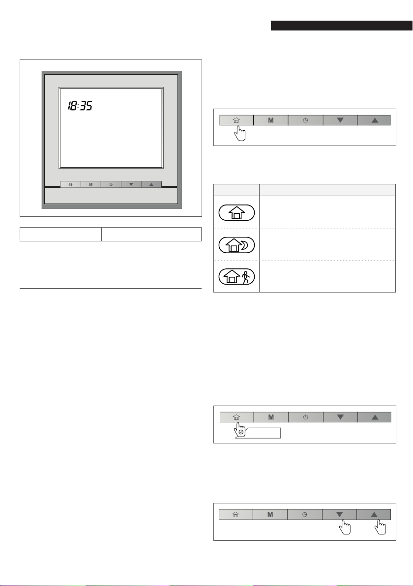
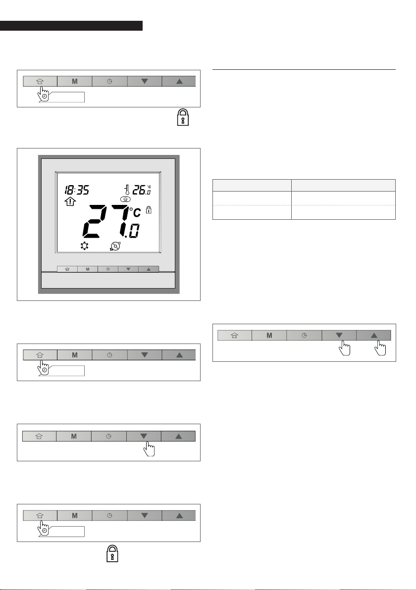
−To set the time, press the Up or Down
buttons.
−Once the hour has been selected,
press the Program button to conrm.
Afterwards, set the minutes and press
the Program button to conrm.
−Conrm all the modications by hold-
ing down the Program button for 2
seconds.
2 sec.
3.2 Setting heating / cooling / DHW
only / off mode
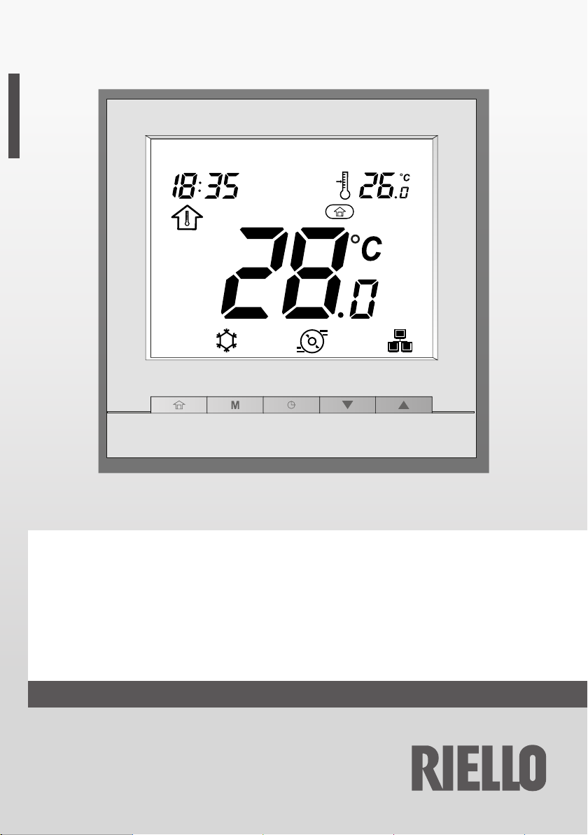
The display of the operating mode depends
on the unit's conguration and the user set-
tings.
ICON DESCRIPTION
Heating
he heat pump heats the water cir-
cuit to the selected setpoint tem-
perature.
Cooling
The heat pump cools the water
circuit to the selected setpoint
temperature.
Domestic hot water only
The heat pump is used to provide
domestic hot water. The cooling
and heating modes are disabled.
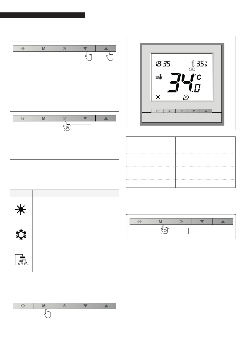
−In order to select the desired operat-
ing mode (heating, cooling, or DHW),
press the Mode button repeatedly.
−The icon corresponding to the select-
ed mode will be displayed.
Example:
THU
Mode Heating
Home mode Home
Temperature
control
Water temperature
control
Water tempera-
ture 34°C
Setpoint 35°C
−In order to shut down the system,
press and hold down the Mode but-
ton for 2 seconds.
2 sec.
−The unit will shut down, but the day
and time will still be shown on the
screen.
9 When the unit is shut off, all the oper-
ating modes described above (cooling /
heating / hot water only) are disabled.
9 Do not deactivate the system's power
supply, if this will ensure that the home
freeze protection function and the wa-
ter freeze protection function will remain
available.

CONTROL UNIT PROGRAMMING
9
Example:
THU
Mode Off
3.3 Setting Home / Sleep / Away
mode
In order to optimize the building's energy ef-
ciency, the control unit can be set with
3 various modes (Home, Sleep, Away), each
with a predened temperature interval.
There are also 3 ways to dene each mode's
intervention.
A. PROGRAMMING
The user can set up to 8 time settings, each
of which is dened by the following param-
eters:
−Activation time
−Mode type (Home, Sleep)
−Day or days of the week for which it
is active
For more information, please refer to the sec-
tion titled "Programming: Assigning the time
frames for the heating and cooling modes”.
B. MANUAL SETTINGS
The user can modify the mode directly from
the screen. This setting will remain in effect
until changed by the user.
−In order to select the mode, press the
Home button repeatedly.
−The icon corresponding to the select-
ed mode will be displayed.
ICON DESCRIPTION
The heat pump operates in
Home mode and the Home set-
point is utilized.
The heat pump operates in
Sleep mode and the Sleep set-
point is utilized.
The heat pump operates in Away
mode and the Away setpoint is
utilized.
C. MODE BLOCK
The selected mode can be blocked for a peri-
od of time specied by the user. All the pro-
gramming will be ignored for the duration of
this time frame.
In order to set the mode block time frame
−Press and hold down the Home but-
ton for 2 seconds.
2 sec.
−The duration of the Home / Sleep /
Away period can be set in either hours
or days. In order to set the number of
hours / days, press the Up or Down
buttons.

CONTROL UNIT PROGRAMMING
10
−To conrm, press and hold down the
Home button for 2 seconds.
2 sec.
−The block icon will be displayed .
Example: Home mode blocked
THU
To cancel the bocked status
−Press and hold down the Home but-
ton for 2 seconds.
2 sec.
−The display will show the remaining
time. Set the counter to "0" by press-
ing the Down button
−To conrm the operation, press and
hold down the Home button for 2
seconds
2 sec.
−The block icon will disappear, and
the program will be reactivated.
3.4 Current setpoint control:
Temperature modication
Two different congurations can be availa-
ble:
−If the user interface is installed on the
unit, the setpoint control is based on
the water's output temperature.
−If the user interface is installed inside
a room (remote user interface), the
setpoint control is based on the room
temperature.
Control type Current setpoint
Local Water setpoint
Remote Air setpoint
In order to obtain improved comfort, the
current setpoint can be adjusted based on
the user's needs.
To adjust the setpoint
−To decrease the temperature, press
the Down button.
−To increase the temperature, press the
Up button.
NOTE:
After a predened period of inactiv-
ity (with no button being pressed),
the setpoint information (air or water
temperatures to be reached) is ob-
scured. By default, the time-out is 10
minutes.

CONTROL UNIT PROGRAMMING
11
Below are two examples
Example 1: water temperature control
In this case the output water temperature is
equal to 34°C, while the setpoint is at 35°C.
THU
Example 2: room temperature control
In this case the detected air temperature is
18°C, and the setpoint is 19°C.
THU
3.5 Viewing the additional data:
Unit general status
When the user interface is installed inside a
room, the indoor air temperature and the air
setpoint are normally shown on the display.
For the interfaces installed on the machine,
the display normally shows the water tem-
perature and the water set point.
In addition to these temperatures, the con-
trol unit also offers the possibility of con-
trolling other parameters, thus allowing the
device's status to be monitored.
A list of these parameters (shown exclusively
in read-only mode) is provided below
No. Description Parameter
number
1External air temperature P001
2Input water temperature P003
3Output water
temperature P004
4Water setpoint
temperature P052
5Saturated suction
temperature P008
6Suction temperature P009
7Overheating temperature P015
8Overheating target
temperature P016
9Discharge temperature P010
10 Refrigerant Temperature P005
11 Required compressor
frequency P022
12 Actual compressor
frequency P023
13 Water control point P051
14 Flow switch status P105
15 Flow switch status P104

CONTROL UNIT PROGRAMMING
12
To view the desired parameter
−Press and hold down the Home but-
ton and the Program button simulta-
neously for 2 seconds.
2 sec.
−The menu's rst parameter will be
displayed.
−Press the Up for Down buttons to
move from one to the next.
−In order to exit the current screen,
press and hold down the Home but-
ton until the initial screen appears on
the display, or else wait 30s for the
time-out to take effect.
until the home screen
is displayed
Example: external air temperature (param-
eter: P001)

CONTROL UNIT PROGRAMMING
13
3.6 Programming: Assigning the time frames for the heating and cooling
modes
The program function (program mode) allows the unit to be congured in such a way that it
operates in a specic mode for a preset period of time. The system allows for the manage-
ment of 8 different modes with dened time frames in which each changeover is determined
by the day or days of the week, by the start time, and by the selected mode.
ID Day of the week Activation
time
Mode
Mon Tue We Thu Fri Sat Dom Home Sleep Away
1 xxxxxxx 06:00 x
2 xxxxx 08:00 x
3 x 12:00 x
4 x x x x 17:00 x
5 xxxxx 22:00 x
6 x x 23:00 x
700:00
800:00
Day Time (start time)
06:00 08:00 12:00 17:00 22:00 23:00
Mon ••••
Tue ••••
We ••••
Thu ••••
Fri ••••
Sat • •
Sun • •
Home
Away
•Sleep

CONTROL UNIT PROGRAMMING
14
Modifying the programming
−To modify the programming, press the
Program button
−Upon accessing the menu, the user
will have the opportunity to modify
the rst programming interval (ID).
Days of the week
−The rst day of the week ("MON”) will
begin to ash. Press the Up or Down
buttons to select "yes” or "no”.
Example: Monday
MON
DAY ID
Status: “yes” or “no”
Press the Program button to conrm your se-
lection.
−The next day ("TUE”) will begin to
ash. At this point, select "yes” or
"no” again as previously described.
−After having set the last day of the
week, ("SUN”), the clock will begin to
ash.
−Press the Up or Down buttons to set
the start time
−Press the Program button to conrm
the start time.
−Once the start time has been set, the
home mode icon will begin to ash.
−Press the Up or Down buttons to set
the home mode.
−Press the Program button to conrm.
−The rst day "MON” will begin to ash.
−Press and hold down the Program
button (ID=1) for 2 seconds to validate
the program.
2 sec.
−The second program will be displayed
(ID=2). To program it, repeat the oper-
ations described above.

CONTROL UNIT PROGRAMMING
15
Modifying a program
Any of the 8 programs can be easily modi-
ed, if necessary.
For example, in order to modify program "2”
−Access the program menu by pressing
the Program button.
−To validate program "1” without mak-
ing any changes, press and hold down
the Program button for 2 seconds.
2 sec.
−Program "2” will be displayed.
−Perform the steps described in the
previous section titled "Modifying the
programming”.
Example:
WED SAT SUN
ID
Activation time 9:00
Days of the week WED, SAT, SUN
Mode HOME
Program ID 8
To exit the program menu
−To exit the program menu at any time,
press and hold down the Home but-
ton for 2 seconds.
2 sec.
Deleting a program
−Access the program menu by pressing
the Program button.
−After having located the program to
be deleted, all the days of the week
with which the program has been as-
sociated must be deselected
−Hold down the Program button for 2
seconds to conrm the deletion of the
program.
2 sec.

ADVANCED PROGRAMMING OPTIONS
16
4 ADVANCED PROGRAMMING
OPTIONS
4.1 Advanced settings: Control unit
programming
The settings menu is used by the technicians
to congure a number of the unit's advanced
settings.
To access the settings menu
−Press and hold down the Home but-
ton and the Program button simulta-
neously for 2 seconds.
2 sec.
−The password screen is displayed.
−Inserire la password.
For user access, enter the following
password: 0000.
−To validate the password and access
the conguration settings, hold down
the Mode button for 2 seconds.
2 sec.
−Press the Up and Down buttons to
navigate the screens.
To exit the settings menu
−Press and hold down the Home but-
ton until the initial screen is displayed.
until the home screen
is displayed
9 For more information on conguring the
advanced settings, please refer to the In-
staller's Manual.
4.2 Domestic hot water mode
It should be noted that domestic hot water
mode (DHW), which allows for the produc-
tion of hot water, only applies to heat pumps
equipped with hot water tanks.
Domestic hot water mode is normally acti-
vated in the case of necessity, and the user
is not required to take any additional action.
9 The domestic hot water program and
the DHW setpoint are set by the installer.
For more information on conguring the
DHW program, please refer to the Install-
er's Manual.
DHW mode can be activated whenever there
are no heating or cooling requirements dur-
ing a certain period.
In order to congure DHW mode
−Press the Mode button repeatedly.
−The icon corresponding to the ACS
mode is displayed.

ADVANCED PROGRAMMING OPTIONS
17
To adjust a different DHW setpoint
−A different DHW setpoint can be con-
gured for the 3 individual modes
(Home, Sleep, Away)
Mode Setpoint acqua
DHW setpoint
DHW Anti-legionella set-
point
DHW Eco setpoint
−Press the Home button to select the
mode.
−Dene the setpoint by pressing the Up
or Down buttons.
4.3 Master/slave control
Large size systems may require certain units
to be interfaced with one another in order
to provide heating/cooling with high output
power levels.
The so-called "master" unit also controls
all the other units, which are referred to as
"slaves".
When the user interface is connected to the
"master" unit, the master/slave icon doesn't
ash.
If the user changes the operating
mode or denes a new setpoint
on the "master" user "interface,
this command will be sent to all
the "slave" units. The "slave"
units execute the command sent
by the master unit.
When the user interface is connected to the
"slave" unit, the master/slave icon ashes
rapidly.
If the user changes the operating
mode or denes a new setpoint
on the "slave" interface, this
command will be ignored. The
operating mode and setpoint
dened by the "master" will be
activated.
When a master/slave communication error
takes place on a certain user interface, the
master/slave icon ashes slowly.
In the event of a master/slave
communication error, the mas-
ter unit will either begin to oper-
ate in stand-alone mode, or else
will continue to operate with the
other "slave" units that have re-
mained connected. The "slave"
unit involved in the communi-
cation error will cease all oper-
ations.
Example: master/slave mode
THU
9 In order to have the units congured
as described above, please contact the
Technical Support Service.

ALARMS AND ERRORS
18
Example:
Current alarm C1
Alarm code 16
Example:
Previous alarm P1
Alarm code 15
To reset the alarms
−From the alarms menu, press and
hold down the Mode and Program
buttons simultaneously for 2 seconds.
5 ALARMS AND ERRORS
5.1 Alarms
The alarms are used to notify the user of
any malfunctions encountered in the heat
pump's components. In the event of an
alarm, the alarm icon will be displayed:
Alarm - Fixed icon
Alarm condition detected; the
unit has stopped.
Alarm - Flashing icon
Condition detected alarm; the
unit is in function.
To view the alarms
−Press and hold down the Mode button
and the Program button simultane-
ously for 2 seconds.
2 sec.
−The alarms menu will be displayed.
−To view the alarms, press the Up or
Down buttons.
Two types of alarms are displayed:
−Current alarms (C-X)
−Previous alarms (P-X).

ALARMS AND ERRORS
19
2 sec.
−The reset alarms menu will be dis-
played.
−Set the alarms to be reset by selecting
"yes" with the Up and Down buttons.
Alarm r5t ("no" mode)
Alarm r5t ("yes" mode)
−To conrm the alarm reset operation,
press and hold down the Mode and
Program buttons simultaneously for 2
seconds.
2 sec.
To exit the alarms screen
−Press and hold down the Home but-
ton until the initial screen is displayed.
until the home screen
is displayed
5.2 Errors
Certain component malfunctions can cause
the user interface to function incorrectly. In
these cases, the error is shown on the screen.
For more information on the errors, please
refer to the Installer's Manual.
Example: E1, error 1
N° Meaning
1Communication error
2
Incorrect conguration (the unit is
not congured for use with the user
interface)
3Proles Table error
4Mandatory parameter not found
5Room temperature sensor error

RIELLO S.p.A.
Via Ing. Pilade Riello, 7
37045 - Legnago (VR)
www.riello.com
The manufacturer strives to continuously improve all products. Appearance, dimensions, technical speci cations, standard equipment
and accessories are therefore liable to modi cation without notice.
Table of contents