manuals.online logo
Brands
  1. Home
  2. •
  3. Brands
  4. •
  5. Riello
  6. •
  7. Relay
  8. •
  9. Riello HYDROLINE RCM NX User manual

Riello HYDROLINE RCM NX User manual

HYDROLINE
Cod. 20081921 Rev. 0
1
3
2
IT
1. Avvertenze preliminari
Questa istruzione è parte integrante del libretto
dell’apparecchio sul quale viene installato il KIT. A tale
libretto si rimanda per le AVVERTENZE GENERALI e per le
REGOLE FONDAMENTALI DI SICUREZZA.
SCHEDA RELÉ GROUPING
2. Versioni
Codici
20081499 Scheda relé grouping
In alcune parti del libretto sono utilizzati i simboli:
ATTENZIONE= per azioni che richiedono particolare
cautela ed adeguata preparazione.
VIETATO= per azioni che non devono essere
assolutamente eseguite.
Rimuovere il mobiletto dell’unità se montato(Solo per
unità RCM NX - RCI NX).
Aprire il quadro elettrico svitando l’apposita vite di
chiusura ,inserire la scheda relay (grouping) nella
apposita sede vedi fig1(RCM NX - RCI NX) fig 2(RK).
Fissare i cavi di alimentazione,il cavo motore e i cavi
di collegamento con le altre unità sotto l’apposito
fermacavo.
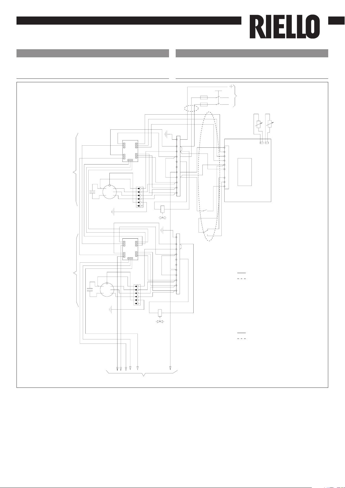
All’interno delle istruzioni di installazione sono presenti
gli schemi elettrici per le unità RCM NX - RCI NX e 2 per
le unità RK.
Effettuare i collegamenti elettrici in funzione del tipo di
3. Composizione del kit
1 Scheda relé grouping 1
2 Istruzioni di installazione 1
3 Schemi elettrici 4
4. Montaggio
EN
1. Preliminary instructions
This instruction booklet is an integral part of the manual
of the device on which you install the kit. In that manual,
please refer to the WARNINGS and the BASIC SAFETY RULES.
MULTI-FUNCTIONAL RELAY BOARD
2. Versions
Codes
20081499 Multi-functional relay board
The following symbols are used in this publication:
WARNING = actions requiring special care and
appropriate training.
DO NOT = actions that MUST ON NO ACCOUNT be
carried out.
Remove the cabinet of the unit ,if installed (RCM NX - RCI
NX units only).
Open the control panel by unscrewing the screw closure,
insert the multi- functional relay board (grouping) in
your dedicate housing,see fig 1 (RCM NX - RCI NX), Figure
2 (RK).
Connect all the cables(motor,power supply etc..), to
other units under the cable holder.
Inside the installation instructions are the wiring
diagrams for units RCM NX - RCI NX and 2 for units RK.
Make the electrical connections according to the type of
unit and system chosen 2/4 pipe(see the wiring diagram).
3. Kit composition
1 Multi-functional relay board 1
2 Installation instruction 1
3 Wiring diagrams 4
4. Mounting
HYDROLINE
Cod. 20081921 Rev. 0
IT
unità.
Dopo avere effettuato i collegamenti richiudere il
quadro elettrico fissando il coperchio con la vite tolta
precedentemente.
Ogni scheda relay è in grado di pilotare una sola unità.
Il numero massimo di unità collegabili ad un solo
comando è di 10.
Cablaggio del costruttore
Cablaggio dell’installatore
AS Sensore aria
WS Sensore acqua
VW Elettrovalvola
TB Morsettiera
EC Contatto esterno
* Opzionale
** Non usate
CS Deviatore cambio stagionale
Sull’unità 1,scollegare il connettore cavo motore CM
collegato ai morsetti (1-2-3-N) della morsettiera TB, tagliare
il relativo connettore e collegare i cavi alla scheda relè
unità 1 morsetti (1-2-3) connettore M2, morsetto N (neutro)
Su tutte le altre unità, lasciare collegato il connettore
cavo motore CM ai morsetti (1-2-3-N) della morsettiera TB
e collegare i cavi provenienti dalla scheda relè (1-2-3-N)
connettore m2+m4 ai morsetti (1-2-3-N) della morsettiera
TB ( serraggio vite)
5. RCM NX - RCI NX
EN
Close the electrical panel with the cover with the screw
removed previously.
Each relay card driving a single unit.
The maximum number of units connected to a single
control is 10.
Factory wiring
Wiring by others
AS Air sensor
WS Water sensor
VW Valve
TB Terminal block
EC External contact
* Optional
** Not used
CS Change over switch
On unit 1 the motor connector CM connected to terminals
(1-2-3-N) of the terminal block TB must be disconnected
and cut. Connected cables to the unit 1 (terminals 1-2-3)
M2 connector and N (neutral)
On all other units the motor connector CM must be left
connected to terminal (1-2-3-N) of the terminal block
TB connect cables from relay board (1-2-3-N) M2+M4
connectors to terminals (1-2-3-N) of the terminal block TB
(tighten screw)
5. RCM NX - RCI NX
HYDROLINE
Cod. 20081921 Rev. 0
25F
25
26F
13CS*
1AS
1WS
HI
L
ME
L
LO
L
VLF
1
N
2
MF
N
3
N
HI
ME
LO
HF LN CC CH WC
1EC* 1CS*
HI
L
ME
L
LO
L
1
N
2
N
3
N
HI
ME
LO
1CM
1IFM
1FC
1IFM
1FC
76 54 LNN321 76 54 LNN321
L
230V-1~50Hz
N
1TB
CN3
RELAY
BOARD
B033386H01
CN1
CN2
UNITA' 1
UNIT 1
LOGIC
TYPE A - AC
REMOTE
CONTROL
RELAY
BOARD
B033386H01
UNITA' 2
UNIT 2
1VW
*
HIGH SPEED
MED SPEED
LOW SPEED
NEUTRAL
LINE
**
**
B
CWR
CUT
TAGLIARE
COUPER
SCHNEIDEN
( NOTE 1 )
1TB
1VW
*
NOTE 2
C
W
R
M1 M2
M3
M4M5
M1 M2
M3
M4M5
*
*
CM
1
2R
CA
4321
Y
C
O
W
B
R
CW
RY
O
B
C
W
R
VALVE
ALLE ALTRE UNITA'
TO THE OTHER UNITS
IT EN
HYDROLINE
Cod. 20081921 Rev. 0
21F
18
22F
11CS*
HI
L
ME
L
LO
L
1
N
2
N
3
N
HI
ME
LO
1EC*
HI
L
ME
L
LO
L
1
N
2
N
3
N
HI
ME
LO
1CS*
VLF MF HF LNCC CH WC
1AS
1WS
PE NNL VHCLC V3 V2 V1
1VW*
1IFM
1CF
1CM
1FC
1IFM
1CF
1CM
1FC
L
230V-1~50Hz
N
RELAY
BOARD
B033386H01
HIGH SPEED
VALVE
NEUTRAL
CN3
CN1
CN2
LOGIC
TYPE A - AC
REMOTE
CONTROL
1TB 1TB
UNITA' 1 / UNIT 1 UNITA' 2 / UNIT 2
1VW*
RELAY
BOARD
B033386H01
LINE
MED SPEED
LOW SPEED
ALLE ALTRE UNITA'
TO THE OTHER UNITS
M1 M2
M3
M4M5
M1 M2
M3
M4M5
*
*
BC
WR
B
CW
R
1
21
53
123456
123456
123456
123456
B
WRY/G
B
C
W
R
Y/G
Y/G
Y/G
C
RIELLO S.p.A. - 37045 Legnago (VR)
tel. +39 0442 630111 - fax +39 0442 22378
www.riello.it
IT
Cablaggio del costruttore
Cablaggio dell’installatore
AS Sensore aria
WS Sensore acqua
VW Elettrovalvola
TB Morsettiera
EC Contatto esterno
* Opzionale
CS Deviatore cambio stagionale
6. RK N
Poiché l’Azienda è costantemente impegnata nel continuo perfezionamento di tutta la sua produzione, le
caratteristiche estetiche e dimensionali, i dati tecnici, gli equipaggiamenti e gli accessori, possono essere soggetti
a variazione.
EN
Factory wiring
Wiring by others
AS Air sensor
WS Water sensor
VW Valve
TB Terminal block
EC External contact
* Optional
CS Change over switch
6. RK N
As the manufacturer is constantly improving its products, the aesthetic or dimensional features, the technical data,
the equipment and accessories indicated could be subject to variations.

This manual suits for next models

1

Popular Relay manuals by other brands

Vemer CLIP-485 user manual

Vemer

Vemer CLIP-485 user manual

ORION ITALIA VFR-1001 instruction manual

ORION ITALIA

ORION ITALIA VFR-1001 instruction manual

Tense RGM-12S user manual

Tense

Tense RGM-12S user manual

Arcteq AQ-S254 instruction manual

Arcteq

Arcteq AQ-S254 instruction manual

ABB C6702 operating instructions

ABB

ABB C6702 operating instructions

ABB T 900 DU V1000 Operation instructions

ABB

ABB T 900 DU V1000 Operation instructions

Megacon Iso4-DIN instruction manual

Megacon

Megacon Iso4-DIN instruction manual

MULTISPAN VPR-22U quick start guide

MULTISPAN

MULTISPAN VPR-22U quick start guide

Pizzato Elettrica CS AR-08 Series manual

Pizzato Elettrica

Pizzato Elettrica CS AR-08 Series manual

Hitachi PN-150BE manual

Hitachi

Hitachi PN-150BE manual

Intellitec 00-00803-400 Service manual

Intellitec

Intellitec 00-00803-400 Service manual

Zamel exta PCM-01 instruction manual

Zamel

Zamel exta PCM-01 instruction manual

Arcteq AQ 1000 instruction manual

Arcteq

Arcteq AQ 1000 instruction manual

ABB SPAJ 160 C User manual and technical description

ABB

ABB SPAJ 160 C User manual and technical description

ABB CVE Instruction leaflet

ABB

ABB CVE Instruction leaflet

Eaton Z-USA Instruction leaflet

Eaton

Eaton Z-USA Instruction leaflet

Siemens SIRIUS 3RP15 operating instructions

Siemens

Siemens SIRIUS 3RP15 operating instructions

hager TX211A instruction manual

hager

hager TX211A instruction manual

manuals.online logo
manuals.online logoBrands
  • About & Mission
  • Contact us
  • Privacy Policy
  • Terms and Conditions

Copyright 2025 Manuals.Online. All Rights Reserved.