Multi Switch –User’s Manual
________________________________________________________________________________________________________
4
1 INTRODUCTION
Congratulations for having chosen Multi Switch system.
This User Manual contains all the information you will need regarding the installation, use, safety and maintenance of
your Multi Switch. Please read the following instructions carefully, as this will allow you to use the product system you
have purchased to its full potential.
Please keep this user manual in a safe place.
© All reproduction of this user manual, whether wholly or in part, is strictly prohibited, without the prior consent of
Producer reserves the right to modify the product without prior notice.
2 GENERAL DESCRIPTION OF THE SYSTEM
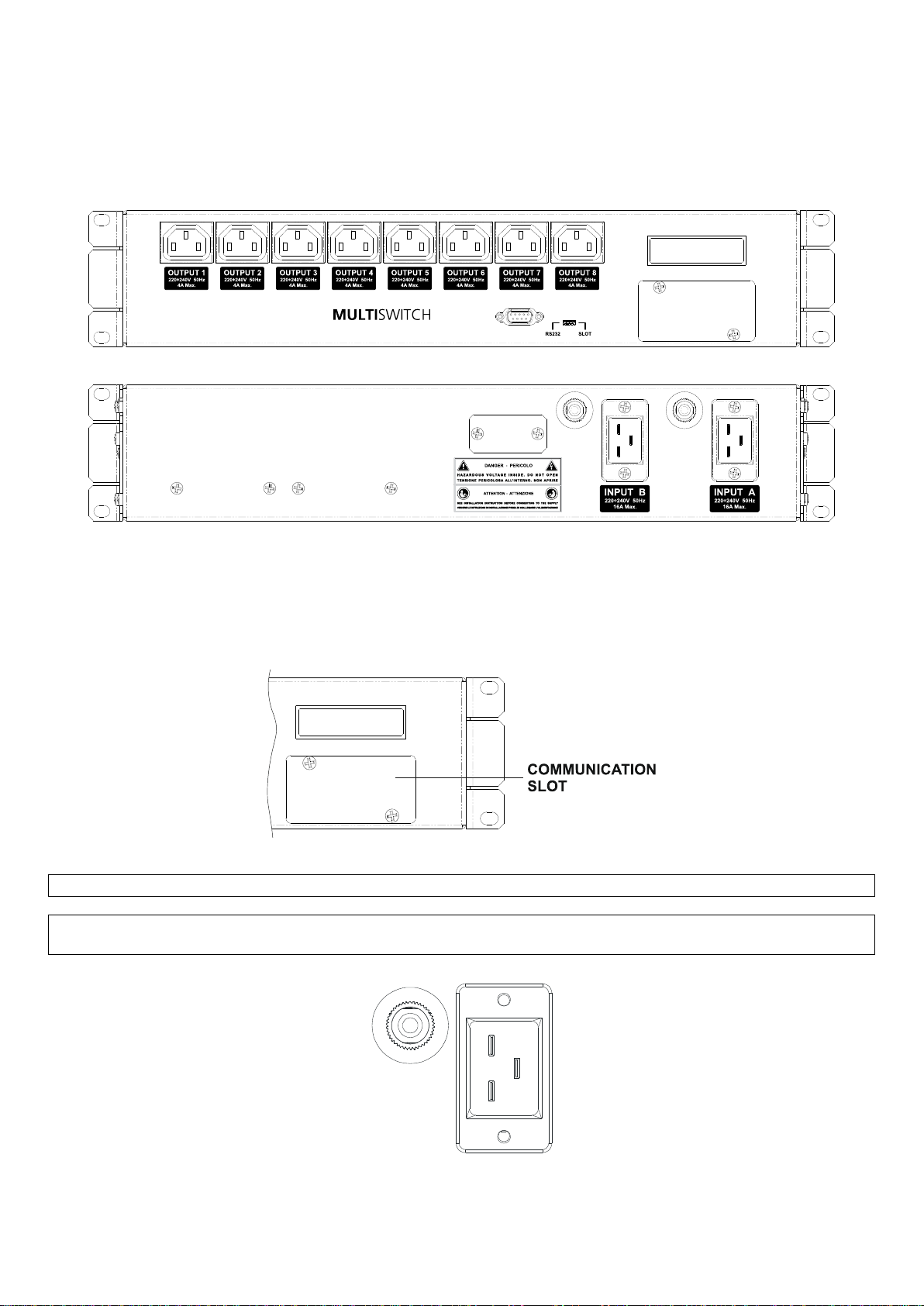
The Multi Switch unit has been designed to allow you to install and manage eight users from a single point, using one
or two power supply lines, either direct from the mains power supply or served by an UPS.
2.1 LOAD DISTRIBUTION
The power supplies have been designed to guarantee operation of the system under extreme conditions:
a single line supplying 180Vac;
two lines simultaneously providing 265Vac.
In this way, the control system is guaranteed to function even with a reduction or strong disturbance in the power
supply.
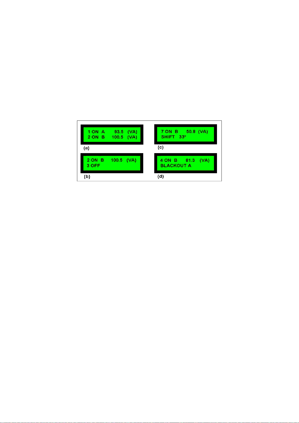
2.2 INTERVENTIONS
The Multi Switch automatically switches the power supply to an alternative source when the loads connected to a line
undergo a blackout. The duration of the voltage blackout required to switch the power supplies can be programmed
using the system’s software.
In order to minimise the intervention time, switching does not just occur when the line voltage reaches zero, but is
instead immediate.
The system will disconnect a load when the current (RMS value) exceeds the maximum value for a single output (4A).
The disconnection of a load occurs within 0.81sec, on average, from the time the current value is exceeded.
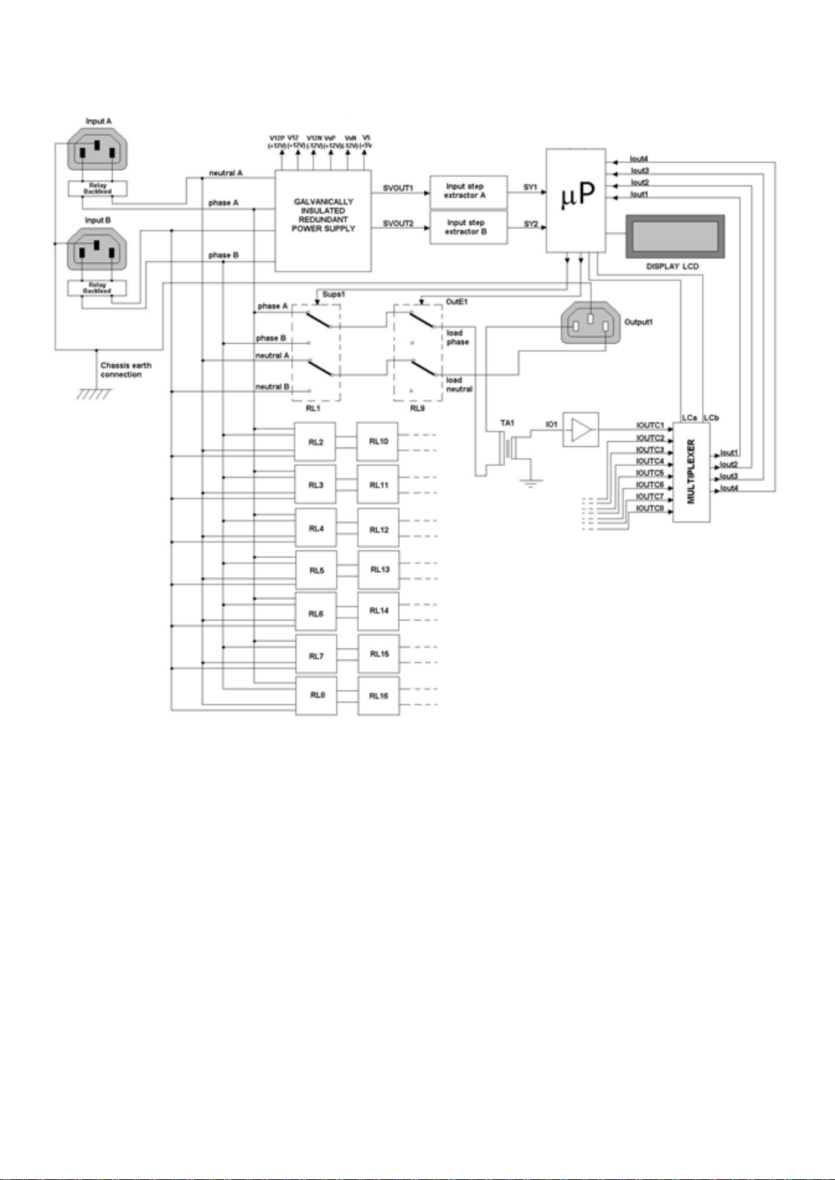
The system is controlled by a microprocessor (P), which carries out all the basic, real-time and communication
functions.
The external communication protocol ensures that all basic functions are activated and that all quantities are
monitored.
The switching system is driven by a series of relays that have been designed and programmed in such a way as to
minimise the intervention times.
In order to ensure that the loads are not accidentally disconnected if a malfunction occurs to the microprocessor, a
“watch-dog” circuit automatically sets the Multi Switch to its default settings, i.e. with all eight users powered by the
main power supply line “A”.
The following figure represents a block diagram of the Multi Switch.