Riels RIL330 User manual

RIELS INSTRUMENTS SRL | ph. +39 049 8961771 | www.riels.it
Before the rst use of the level meter please read carefully the instructions provided in this User's Guide
and keep it for future use. The manufacturer reserves the right to make changes without previous notice.
INSTRUCTION MANUAL
Ultrasonic Level Meters RIL330
Ultrasonic Level Meters RIL33

RIELS INSTRUMENTS SRL | ph. +39 049 8961771 | www.riels.it

RIELS INSTRUMENTS SRL | ph. +39 049 8961771 | www.riels.it
1 .
Basic description
......................................................................................................................4
2 .
Range of application
.................................................................................................................5
3 .
Variants
.....................................................................................................................................5
4 .
Dimensional drawing.................................................................................................................5
5 .
Installation and putting into operation
.......................................................................................6
6 .
Mechanical mounting
................................................................................................................6
7 .
Electrical connection
.................................................................................................................10
7.1. Connection through ISO connector...................................................................................10
7.2. Connection through M12 connector..................................................................................11
7.3. Connection via PG 11 gland or gland for protective hoses...............................................12
8 .
Control elements
.......................................................................................................................14
9 .
Settings
.....................................................................................................................................15
9.1. Setting procedure for level meters RIL330
........................................................................15
9.2. Setting procedure for level sensors RIL331
.....................................................................17
10 .
Function and status indication.................................................................................................19
11 .
Protocol Modbus®....................................................................................................................20
12 .
Order code
..............................................................................................................................20
13 .
Correct specication examples
...............................................................................................21
14 .
Accessories.............................................................................................................................21
15 .
Safety, protection, compatibility and explosion proof
..............................................................22
16 .
Use, manipulation and maintenance.......................................................................................22
17 .
General conditions and warranty
............................................................................................23
18 .
Marking of labels
.....................................................................................................................23
19 .
Technical specications
..........................................................................................................25
19 .
Packing, shipping and storage
................................................................................................27

RIELS INSTRUMENTS SRL | ph. +39 049 8961771 | www.riels.it
4
To ensure maximum safety of control processes, we have dened the following safety instructions
and information. Each instruction is labelled with the appropriate pictogram.
Alert, warning, danger
This symbol informs you about particularly important instructions for installation and operation of
equipment or dangerous situations that may occur during the installation and operation. Not observing
these instructions may cause disturbance, damage or destruction of equipment or may cause injury.
Information
This symbol indicates particularly important characteristics of the device.
Note
This symbol indicates helpful additional information.
All operations described in this instruction manual have to be carried out by trained personnel
or by an accredited person only. Warranty and post warranty service must be exclusively
carried out by the manufacturer.
Improper use, installation or set-up of the sensor can lead to crashes in the application.
The manufacturer is not responsible for improper use, loss of work caused by either direct
or indirect damage, and for expenses incurred at the time of installation or during the period
of use of the level sensors.
The
RIL330
ultrasonic
level
meters
and
the
RIL331
ultrasonic
level
sensors
are
compact
measurement
devices
containing
an
electro-acoustic
transducer
and
an
electronic
module.
Using
the
electro-acoustic
transducer,
level
meters
and
level
sensors
transmit
a
series
of
ultrasonic pulses that spread towards the surface. The transducer then receives the reected
acoustic wave, which is subsequently processed in the electronic module. The current distance
to the surface level is calculated from the time of spread of individual pulses towards the surface
and back and the temperature measured in the tank. The output is then set on the basis of the
surface height.
The outputs of the RIL330 level meter are current 4 -20 mA, voltage 0 - 10 V and industrial
line RS-485 with Modbus RTU communication. The output of the RIL331 sensor consists of a
PNP transistor with an open collector and a two-state current switch 4 mA / 20 mA.

RIELS INSTRUMENTS SRL | ph. +39 049 8961771 | www.riels.it
5
RIL330 –_ –01–_ measurement range 0.1 m to 1m, all-plastic design, source of PVDF
(polyvinylidene uoride), mechanical connection with thread G ¾.
–_ –02–_ measurement range 0.20 m to 2m, all-plastic design, source of PVDF,
mechanical connection with thread G 1''.
–_ –06–_ measurement range 0.20 m to 6m, all-plastic design, source of PVDF,
mechanical connection with thread G 1 ½".
–_ –10–_ measurement range 0.4 m to 10m, all-plastic case, source of PVDF,
mechanical connection with thread G 2 ¼“.
–_ –20–_ measurement range 0.5 m to 20m, all-plastic case, source of PVDF,
mechanical connection with ange of aluminium alloy.
Thanks to the contactless measuring principle ultrasonic level meters are suitable for continuous
measurement or limit level sensing of liquids, waste water, sludge, suspensions, adhesives, resins
in various open and closed vessels, sumps, open channels and drains. Use for organic solvents or
substances, which contain organic solvents, should be consulted with the manufacturer. Usability
for level measurement of solid materials is limited, there is a shorter measuring range. We recom-
mend using the level meter for such a medium to consult with the manufacturer. Setting is carried
out either using two buttons or a magnetic pen or by remote setting in case of Modbus RTU output.
The device is equipped with optical indication of its state (RUN) and the setting process (STATE). It
is manufactured in designs for normal (N) and explosive atmospheres (Xi).
RIL330–_–02–_ RIL330–_–06–_RIL330–_–01–_
In the case of use for an aggressive medium is necessary to prove the chemical compatibility
of used materials of the sensor (Tab. Used materials on page 27). The guarantee ceases when
the product is chemically damaged.
RIL330
RIL330
RIL330
RIL330

RIELS INSTRUMENTS SRL | ph. +39 049 8961771 | www.riels.it
6
ground
terminal
RIL330–_–10–_ RIL330–_–20–_
Al alloy
• The device is installed in a vertical position into the upper lid of the tank or reservoir using a
lug, a fastening nut or a ange in such a way that the axis of the device is perpendicular to the
surface level of the measured liquid (Fig. 1). Tightening of the level meter in the welding ange
(or. by the xing nut) must be done only by hand *. The device shall be installed in places
with no risk of mechanical damage to the front of the sensor.
• The minimum distance from the tank wall when installing into the lid or the ceiling of the tank
are listed in Fig. 3. In the case of device installation close to smooth wall of the tank it is not
necessary to observe the minimum distance, conversely it is suitable to shorten this distance.
• When installing in an open channel (sump, drain, etc.), install the device onto a console as
close as possible to the expected maximum level.
• The reference plane for the measurement is the lower edge of the transducer (Fig.2). In compli-
ance with the measuring principle, no signals reec ted in the are a directl y b elow the device
(dead zone) can be evaluated. The dead zone (Fig. 2) determines the minimum distance possible
between the device and the highest level. The minimum distances to the medium are listed in
the chapter "Technical specications".
• The device shall be installed so that the surface does not interfere with the dead zone when
the tank is lled to the maximum. If the measured surface interferes with the dead zone, the
device will not measure properly.
*) To loosen the level meter can be used suitable wrench.
Please follow next 3 steps:
•
•
•
•

RIELS INSTRUMENTS SRL | ph. +39 049 8961771 | www.riels.it
7
Fig. 1: Correct installation of the sensor,
perpendicular to the liquid surface
RIL330–01 ; 02 ; 10 d > c/12
(min. 200 mm)
RIL330–06 d > c/8
(min. 200 mm)
RIL330–20 d > c/10
(min. 200 mm)
d – distance from tank wall
c – maximum reach of the device
m – dead zone
Fig. 2: Dead zone of the
device
Fig. 3: Distance of the device
from the tank wall
reference plane for
the measurement
• D o n o t i n s t a l l t h e d e v i c e in or a b o v e
the lling p o int ( Fig. 4) . T h e m e as-
urement could be aected by the
inowing medium.
Fig. 4: Installation of the device out of reach of lling circulation
It is recommended to avoid placing the sensor into a narrow neck.
• Only if the maximum level in the tank gets into the dead zone, the device shall be mounted into
a higher installation neck. The tank can be then lled nearly up to the maximum volume. The
neck’s inner surface shall be even and smooth (without edges and welded joints), the inner
edge should be rounded in the spot where the ultrasonic wave leaves the pipe. Choose the
largest possible neck diameter, but keep the neck height as low as possible. The recommended
dimensions of the inlet neck are listed in Fig. 5.
Fig. 5: Installation of the device in the installation neck
RIL330–01; 02; 06; 10 a < 1.5b
b > 100 mm
RIL330–20 a < 1.5 b
b > 150 mm
!
a – neck height from source edge
b – neck width
m – dead zone
min. 10 mm

RIELS INSTRUMENTS SRL | ph. +39 049 8961771 | www.riels.it
8
• If the level sensor is mounted into narrow necks and into places with obstacles, close uneven
walls or the lling area, where the transmission signal could be distorted, we recommend us-
ing a guide tube (acoustic horn). The tube must be made from a single material with a smooth
inner surface (see image 6 a 7). The minimum tube diameter must have the dimension „h“
according to see to table at image 7. The construction of the guide tube we recommend
to consult with the manufacturer.
Fig. 6: Short guide tube
installation
h
ventilation
holes
sleeves for
mounting
h
Fig. 7: Total guide
tube installation
RIL330–01 h ≥ 50 mm
RIL330–02 h ≥ 70 mm
RIL330–06 h ≥ 100 mm
RIL330–10 h ≥ 150 mm
RIL330–20 h ≥ 200 mm
Fig. 8: Horn adapter installation
Horn adapter ST
• The site for installing the level meter needs to be chosen so that the emitted acoustic
signal is not aected by nearby objects (reinforcements, supports, brackets, ladders,
heating elements, mixers, etc.). These obstacles may result in false rebounds, increasing
measurement inaccuracy (Fig. 9).
x – distance from the edge of the longest object
c – maximum reach of the level meter
RIL330–01 ;02 ; 10 x > c/12
(min. 200 mm)
RIL330–06 x > c/8
(min. 200 mm)
RIL330–20 x > c/10
(min. 200 mm)
Fig. 9: Minimum distance from close objects in the tank
•
Horn adapter
for improved reception of the transmitted
signal
can
be
used
in
open
channels,
sumps,
tanks,
etc. ST–G0,75 (G1, G1,5, G2,25) by type RIL330.
•
Horn adapter ST increases the directivity of the emitted
acoustic waves, improves the reception of weak echoes
(unstable
surface
level,
loose
materials,
foam
on
the
level) and reduces the risk of false reections.
•
The horn adapter is installed on the device via process
connection G3/4“ (ST–G0,75) or G1” (ST–G1) or G1½”
(ST–G1,5), or G 2 ¼“ (ST–G2,25).

RIELS INSTRUMENTS SRL | ph. +39 049 8961771 | www.riels.it
9
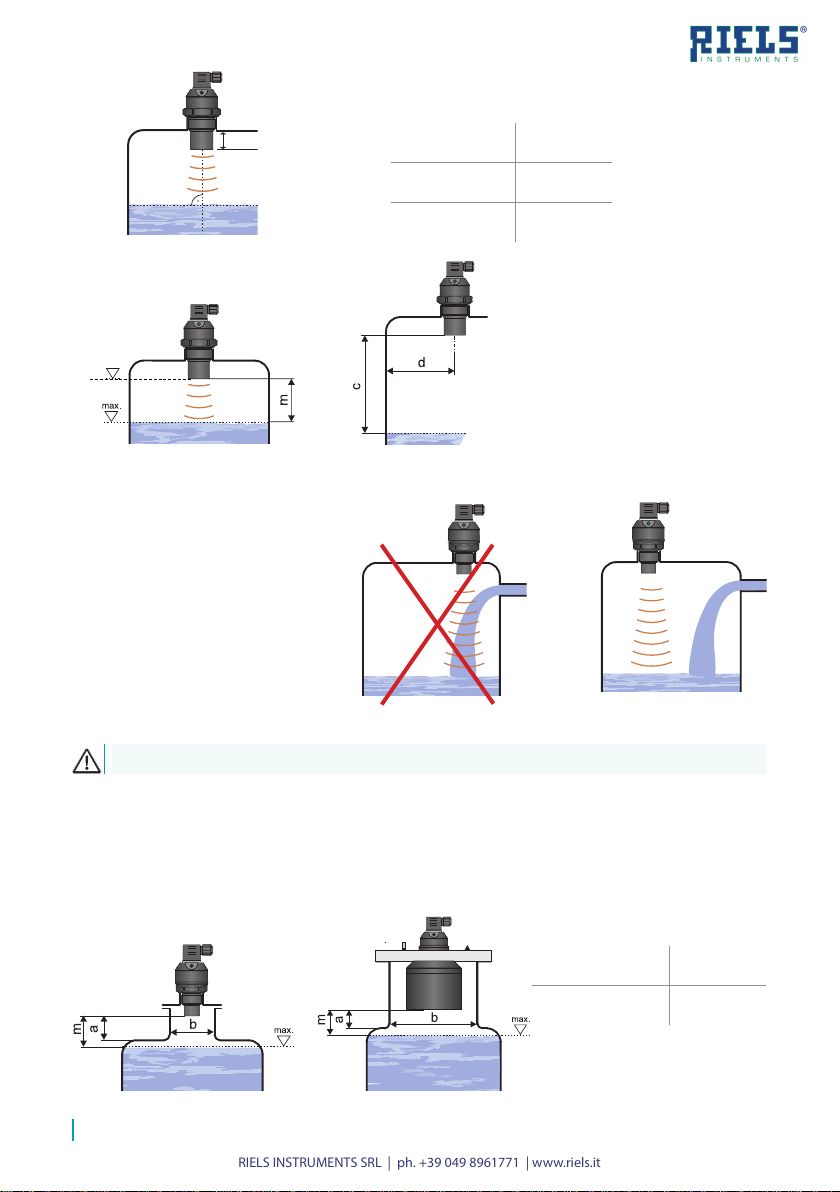
• Foam may be produced on the surface of the measured
liquid during lling, mixing and other processes. The thick
foam signicantly absorbs the ultrasound signal and may
cause malfunction of the device (Fig. 10). In those cases
it is necessary to test the device in advance or contact the
manufacturer . In case of a thin layer of foam, it is also
possible to use directional horn for improving receipt of the
reected echo.
!
Fig. 10: Thick foam on the surface
• The ultrasonic signal can be scattered or attenuated if
the surface is moderately stirred or rippled (due to a
mixer, inow of liquid, etc.). This may result in reduction
of the measurement range or unreliable operation of the
device (Fig. 11). For a rippled or swirling level, you can
use the directional horn to eliminate scattering of the
ultrasonic signal.
Fig. 11: Moderately stirred
surface
!
• False surface reections of the ultrasonic
signal and unreliable operation of the de-
vice might result from the mixer’s rotating
blades t h a t r i p p l e t h e s u r f ac e l e v e l (Fi g . 12) .
• The device should not be installed in places
with the risk of false reections of the
ultrasonic signal from the mixer’s blades
(Fig. 13).
!
Fig. 12: Strongly stirred
surface
Fig. 13: False reection
from mixer blades
• The measuring device shall not be installed in
places with direct sunlight and shall be protected
against weather conditions. Direct sunlight af-
fects the built-in temperature compensation!
• If installation in places with direct sunlight is
inevitable, it is necessary to mount a shielding
cover above the device (Fig. 14).
• It is advisable to keep cable under the cable
gland (s a g ging d own) a s show n in Fig. 15 to p re -
ven t p e n etrat i o n of m o i s ture. R a i n a n d c o n d ens-
ing water can be therefore drained away freely.
• The cable gland as well as the connector shall
be tightened suciently to prevent penetra-
tion of moisture.
Fig. 14: Shielding cover against direct
sunlight
Fig. 15: Protection against
penetration of moisture

RIELS INSTRUMENTS SRL | ph. +39 049 8961771 | www.riels.it
10
wire cross-section 0.5 to 0.75 mm
2), via a detachable ISO connector
with inner screw terminals, which is part of the delivery. The
connection diagram and the inner view of the connector are
shown in Fig.16 and 17. Non-detachable connector IP67 with
PVC cable 5 m long can be supplied as an extra option.
Connecting the cable to the device:
1. Unscrew the connector from the device body using a suitable screwdriver.
2. Remove the inner part of the connector using a at screwdriver (insert the screwdriver in the
gap marked with an arrow).
3. Unscrew the cable gland and pull the supply cable inside the connector.
4. Connect the cable wires to the screw terminals as shown in Fig. 16 (current output 4-20 mA),
Fig. 17 (voltage output 0-10 V), Fig. 18 (S type output) or Fig. 19 (P) type output. Tighten the
terminals rmly.
5. Insert the terminals back in the connector so that the NC terminal points away from the cable
gland. Fasten the cable gland.
6. Check the sealing on the connector and attach the connector back to the device body.
Valid for: RIL33_-_-_ _-_-_-G-_
Performance„G“
with connector ISO
0 V (2)
+U (1)
meter (variant –I) and inside view of the connector
BN ()1
BU ()2
mA +U
0V
V
+U
0V
U
Uout
V
+U
0V
U
Uout
mA +U
0V
0V
BN (1)
BU (2)
+U
0V
BN (1)
BU (3)
BK (4)
BN ()1
BU (3)
BN ()1
BU ()2
BK (3)
BN ()1
BU (3)
BK (4)
BN ()1
BU ()2
mA +U
0V
mA +U
0V
BN ()1
BU (3)
Uout (3)
+U (1)
0 V (2)
BN ()1
BU ()2
mA +U
0V
V
+U
0V
U
Uout
V
+U
0V
U
Uout
mA +U
0V
+U
0V
BN (1)
BU (2)
BK (3)
+U
0V
BN (1)
BU (3)
BK (4)
BN ()1
BU (3)
BN ()1
BU ()2
BK (3)
BN ()1
BU (3)
BK (4)
BN ()1
BU ()2
mA +U
0V
mA +U
0V
BN ()1
BU (3)
+U (1)
Fig. 18: Connection diagram of the RIL331 sensor with S
type output (two-state current switch 4 mA / 20 mA)
BN ()1
BU ()2
mA +U
0V
V
+U
0V
U
Uout
V
+U
0V
U
Uout
mA +U
0V
+U
0V
BN (1)
BU (2)
BK (3)
+U
0V
BN (1)
BU (3)
BK (4)
BN ()1
BU (3)
BN ()1
BU ()2
BK (3)
BN ()1
BU (3)
BK (4)
BN ()1
BU ()2
mA +U
0V
mA +U
0V
BN ()1
BU (3)
0 V (2)
Type RIL331–_–_ _–_–S–G–_
Positive supply pole +U is connected
to the brown wire or to connector pin
1, negative pole to the blue wire or to
connector pin 2.
The RIL330 level meter or RIL331 level sensor with a G type
cable gland are connected to processing (display) units by
means of a cable with an outer diameter of 6 to 8 mm (recommended
Fig. 16: Connection diagram of the RIL330 level Fig. 17: Connection diagram of the RIL330 level
meter (variant –U) and inside view of the connector

RIELS INSTRUMENTS SRL | ph. +39 049 8961771 | www.riels.it
11
Q (3)
+U (1)
0 V (2)
Fig. 19: Connection diagram of the ULS sensor with P type output
(PNP) with an open collector
BN ()1
BU ()2
mA +U
0V
V
+U
0V
U
Uout
V
+U
0V
U
Uout
mA +U
0V
+U
0V
BN (1)
BU (2)
BK (3)
+U
0V
BN (1)
BU (3)
BK (4)
BN ()1
BU (3)
BN ()1
BU ()2
BK (3)
BN ()1
BU (3)
BK (4)
BN ()1
BU ()2
mA +U
0V
mA +U
0V
BN ()1
BU (3)
legend:
BK – black BN – brown
BU – blue NC – not connected
(display) units by means of a cable with an outer diameter of 4 to 6 mm (recommended wire cross-
section 0.5 to 0.75 mm2), via a connector socket with a moulded cable (2 or 5 m long) or via a
detachable connector socket without a cable (see accessories), the connector is not basic part of
the sensor. In this case connect the cable to the inner socket pins under Fig. 21.
legend:
BN – brown
BK – black
BU – blue
output (BK)
0V (BU)
+U (BN)
Fig. 20: Inside view of the
connector socket
Performance„C“
with connector M12
Valid for: RIL330-_-_ _-_-_-C-_
1
3
4
0 V (3)
+U (1)
BN ()1
BU ()2
mA +U
0V
V
+U
0V
U
Uout
V
+U
U
Uout
mA +U
0V
+U
0V
BN (1)
BU (2)
BK (3)
+U
0V
BN (1)
BU (3)
BK (4)
BN ()1
BU (3)
BN ()1
BU ()2
BK (3)
BN ()1
BU (3)
BK (4)
BN ()1
BU ()2
mA +U
0V
mA +U
0V
BN ()1
BU (3)
Type RIL331–_–_ _–_–P–G–_
Positive supply pole +U is connected
to the brown wire or to connector pin
1, negative pole to the blue wire or to
connector pin 2. Load is connected to
the black wire or to connector pin 3.
The RIL330 level meter or ULS level sensor with a C type cable gland are connected to processing
Type
RIL330–_–_ _–_–I–C–_ The
positive
supply
pole
+U
is
connected to connector pin 1 or the
brown
wire
of
the
connected
cable,
the
negative
pole
is
connected
to
connector pin 3 or the blue wire of the
connected cable. Fig. 21: Connection diagram of the RIL330 level
meter
(variant –I) and view of the connector

RIELS INSTRUMENTS SRL | ph. +39 049 8961771 | www.riels.it
12
1
3
4
0 V (3)
+U (1)
Uout (4)
BN ()1
BU ()2
mA +U
0V
V
+U
0V
U
Uout
V
+U
0V
U
Uout
mA +U
0V
+U
0V
BN (1)
BU (2)
BK (3)
+U
0V
BN (1)
BU (3)
BK (4)
BN ()1
BU (3)
BN ()1
BU ()2
BK (3)
BN ()1
BU (3)
BK (4)
BN ()1
BU ()2
mA +U
0V
mA +U
0V
BN ()1
BU (3)
1
3
4
0 V (3)
+U (1)
1
3
4
0 V (3)
+U (1)
Uout (4)
Fig. 23: Connection diagram of the RIL331 sensor
with S type output (two-state current switch 4
mA / 20 mA)
Fig. 24: Connection diagram of the RIL331 sensor with P
type output (PNP) with an open collector
BN ()1
BU ()2
mA +U
0V
V
+U
0V
U
Uout
V
+U
0V
U
Uout
mA +U
0V
+U
0V
BN (1)
BU (2)
BK (3)
+U
0V
BN (1)
BU (3)
BK (4)
BN ()1
BU (3)
BN ()1
BU ()2
BK (3)
BN ()1
BU (3)
BK (4)
BN ()1
BU ()2
mA +U
0V
mA +U
0V
BN ()1
BU (3)
BN ()1
BU ()2
mA +U
0V
V
+U
0V
U
Uout
V
+U
0V
U
Uout
mA +U
0V
+U
0V
BN (1)
BU (2)
BK (3)
+U
0V
BN (1)
BU (3)
BK (4)
BN ()1
BU (3)
BN ()1
BU ()2
BK (3)
BN ()1
BU (3)
BK (4)
BN ()1
BU ()2
mA +U
0V
mA +U
0V
BN ()1
BU (3)
Type RIL331–_–_ _–_–S–C–_
The positive supply pole +U is
connected to connector pin 1 or the
brown wire of the connected cable,
the negative pole is connected to
connector pin 3 or the blue wire of
the connected cable.
Type RIL331–_–_ _–_–P–C–_
The positive supply pole +U is
connected to connector pin 1 or the
brown wire of the connected cable,
the negative pole is connected to
connector pin 3 or the blue wire
of the connected cable. Load is
connected to connector pin 4 or
the black cable wire.
a xed of PVC cable 5 m long. PG 11 (B) or plastic bushings with
a thread for protective hoses (H) can be used as a cable gland.
Connection diagrams are shown in Fig. 25, 26, 27, 28 and 29.
Valid for: RIL330-_-_ _-_-_-B(H)-_
Performance „B“ with short
cable gland Performance „H“with cable
gland for protective hose
Type
RIL330–_–_ _–_–U–C–_
The
positive
supply
pole
+U
is
connected to connector pin 1 or the
brown wire of the connected cable,
the
negative
pole
is
connected
to
connector
pin
3
or
the
blue
wire
of
the
connected
cable.
Output
voltage is connected to connector
pin 4 or the black cable wire.
Fig. 22
(
:
v
C
a
o
ri
n
a
n
n
e
t
c
–
t
U
io
)
n
a
d
n
i
d
a
g
v
r
ie
a
w
m
o
o
f
f
t
t
h
h
e connector
e RIL330 level meter
The
RIL330
level
meter
or
ULS
sensor
with
a
B
or
H
type
cable gland
are
connected
to
processing
(display)
units
by
means
Type
RIL330–_–_ _–_–I–B(H)–
_The positive supply pole +U is
con-
nected
to
the
brown
wire
of
the
connected cable, the negative pole
is connected to the blue wire of the
connected cable.
Fig. 25: Connection diagram of the
RIL330 level meter (variant –I)

RIELS INSTRUMENTS SRL | ph. +39 049 8961771 | www.riels.it
13
It is also necessary to design and take measures to reduce the effects of static electricity to
a safe level in the wiring.
Installation in explosive atmospheres needs to be carried out in compliance with EN 60079-14
(Electrical installations for explosive gaseous atmospheres – Part 14: Electrical installations
in dangerous areas other than mining) and possibly also in compliance with other standards
relating to the area concerned.
Fig. 27: Connection diagram of the level meter
with an RS–485 output (variant –M)
Fig. 28: Connection diagram of the ULS sensor
with S type output (two-state current switch 4
mA / 20 mA)
BN ()1
BU ()2
mA +U
0V
V
+U
0V
U
Uout
V
+U
0V
U
Uout
mA +U
0V
+U
0V
BN (1)
BU (2)
BK (3)
+U
0V
BN (1)
BU (3)
BK (4)
BN ()1
BU (3)
BN ()1
BU ()2
BK (3)
BN ()1
BU (3)
BK (4)
BN ()1
BU ()2
mA +U
0V
mA +U
0V
BN ()1
BU (3)
Fig. 29: Connection diagram of the ULS sensor
with P type output (PNP) with an open collector
+U
0V
BN (1)
WH, BU (2)
+U
0V
BN (1)
BU (2)
BK (3)
legend:
BK – black WH – white
BU – blue YE – yellow
BN – brown GN – green
The supply source should be preferably designed as a stabilized source of safe voltage 18 V
to 36 VDC (max. 30 V DC for versionXi), which is partof the downstream processing ordisplay system.
In case of strong ambient electromagnetic disturbance, parallel run of the input cable with the power
line or its length exceeding 30 m, we recommend using a shielded cable.
Type
RIL330–_–_ _–_–U–B(H)–_ The positive
supply pole +U is connected to the
brown wire of the connected cable, the negative
pole is connected to the blue wire of the connect-
ed cable. Output voltage is connected to the black
wire of the cable.
Type
RIL330–_–_ _–_–M–B(H)–_ Level
meters are designed for connection to the
PLC input (RS–485). The positive supply pole +U
is connected to the brown wire of the connected
cable, the negative pole is connected to the blue
wire of the connected cable. Terminals A and B
of
line
RS-485
are
connected
to
the
yellow
and
green communication wires. The ground terminal
of line RS-485 is connected to cable shielding.
Type
RIL331–_–_ _–_–S–B(H)–_
The positive supply pole +U is connected to the
brown wire of the connected cable, the negative
pole is connected to the blue wire of the connect-
ed cable.
Type
RIL331–_–_ _–_–P–B(H)–_
The positive supply pole +U is connected to the
brown wire of the connected cable, the negative
pole is connected to the blue wire of the connect-
ed cable. Load is connected to the black wire of
the cable.
Fig. 26: Connection diagram of the RIL330
level
meter with a voltage output (variant –U)
Wiring operations shall only be carried out without voltage!
Taking into account the potential occurrence of electrostatic discharge on non-conducting
parts of the level meter, it is necessary to ground the ange of level meters RIL330–Xi–
20–F
and sensors RIL331–Xi–20–F, located in an explosive atmosphere, using a ground terminal!

RIELS INSTRUMENTS SRL | ph. +39 049 8961771 | www.riels.it
14
DOWN button ("OFF")
UP button ("ON")
LED indicator
“STATE”
LED indicator
“RUN”
connector
Ultrasonic transmitter
locking screw
Fig. 30: Key parts of the measuring device
(version with buttons)
EMPTY sensitive area
("OFF")
FULL sensitive area
("ON")
LED indicator
“STATE”
LED indicator
“RUN”
connector
Ultrasonic transmitter
locking screw
Fig. 31: Key parts of the measuring
device (version with Hall probes)
Valid for: RIL330-_-_ _-_-_-_-T
Valid for: RIL330-_-_ _-_-_-_-M
DOWN
button for RIL330 (or
"OFF"
for ULS)
•
open the setting mode
•
for RIL330: direct setting of the value 4mA (0
V)
•
for RIL331: setting limit for output disconnection
•
decrease of values in dened steps
UP
button for RIL330 (or
"ON"
for ULS)
•
open the setting mode
•
for RIL330: direct setting of the value 20
mA (10
V)
•
for RIL331: setting limit for output connection
•
increase of values in dened steps
EMPTY
at area for RIL330 (or
"OFF"
for ULS)
•
open the setting mode
•
for RIL330: direct setting of the value 4
mA (0
V)
•
for RIL331: setting limit for output disconnection
FULL
at area for RIL330 (or
"ON"
for ULS)
•
open the setting mode
•
for RIL330: direct setting of the value 20
mA (10V)
•
for RIL331: setting limit for output connection

RIELS INSTRUMENTS SRL | ph. +39 049 8961771 | www.riels.it
15
The level meter works most often in its default mode for level measurement (Fig. 32) and only rarely
in the inverse mode (Fig. 33).
The manual device shall be set up after installation using the DOWN and UP buttons (for version
“T”) or by applying the magnetic pen onto sensitive at areas (for version “M”). The set-up process
is indicated by the STATE indicator lamp.
The L version level meter does not have any setting controls and indication LEDs. Pre-dened
ranges are factory set (applicable to current and voltage outputs).
The level meter variant with a Modbus type output is set by means of two-way communication via
the RS-485 industrial bus with the Modbus RTU protocol. A list of applicable registers is given in a
separate appendix. To set up the level meter and collect measured data, you can use the software
application „Basic SCADA level“, which is freely available to tecnico@riels.it
Fig. 32: Default mode
(level measurement)
Fig. 33: Inverse mode
Connect the level meter to the supply source. Check the output value - current or voltage - using the
measuring device or a connected instrument.
(version “T”)
a) Basic mode (level measurement)
1. Drain the tank to the lower measured level.
2. Press the DOWN button for at least 2 s to activate the setting mode (the STATE indicator LED
ashes slowly). Keep the DOWN button pressed for at least additional 3 s to set the value to 4
mA (0
V) directly. In that case you can skip step 3.
3. Press the DOWN and UP buttons to accurately set any value in individual increments (hold the
relevant button to increase the adjustment step gradually).
4. Press both buttons simultaneously for at least 1 s to conrm the set values. The STATE indicator
LED briey ashes three times.
5. Any other setting is possible 2 s after both buttons are released.

RIELS INSTRUMENTS SRL | ph. +39 049 8961771 | www.riels.it
16
1. Fill the tank up to the upper measured level.
2. Press the UP button for at least 2 s to activate the setting mode (the STATE indicator LED
ashes quickly). Keep the UP button pressed for at least additional 3 s to set the value to 20 mA
(10 V) directly. In that case you can skip step 3.
3. Press the DOWN and UP buttons to accurately set any value in individual increments (hold the
relevant button to increase the adjustment step gradually).
4. Press both buttons simultaneously for at least 1 s to conrm the set values. The STATE indicator
LED briey ashes three times.
5. Any other setting is possible 2 s after both buttons are released.
1. Disconnect the level meter from supply voltage (e.g. by disconnecting the connector).
2. Press the DOWN and UP buttons at the same time while supply voltage is disconnected.
3. Connect supply voltage while keeping the DOWN and UP buttons pressed.
4. Wait approx. 4 s for 3 short ashes of the orange STATE indicator LED. After that, release both
buttons.
5. Now the level meter is set to factory default. See the table on page 26.
b) Inverse mode
In the inverse mode, set the lower limit of 4 mA (0 V) when the tank is lled up to the upper meas-
ured surface level and the upper limit of 20 mA (10 V) when the tank is drained to the lower meas-
ured surface level see Fig. 34.
(version “M”)
a) Basic mode (level measurement)
6. Drain the tank to the lower measured level.
7. Set the level meter output to the value of 4 mA (0 V) by applying the magnetic pen to the EMPTY
sensitive area for at least 2 s. The STATE indicator LED ashes slowly. Hold the magnetic pen
on the at area for at least additional 3 s to conrm the set value and store it in the internal
memory of the level meter. The STATE indicator LED briey ashes three times.
8. Any other setting is possible 2 s after the magnetic pen is removed from the sensitive area.
1. Fill the tank up to the upper measured level.
2. Set the level meter output to the value of 20 mA (10 V) by applying the magnetic pen to the
FULL sensitive area for at least 2 s. The STATE indicator LED ashes slowly. Hold the magnetic
pen on the at area for at least additional 3 s to conrm the set value and store it in the internal
memory of the level meter. The STATE indicator LED briey ashes three times.
3. Any other setting is possible 2 s after the magnetic pen is removed from the sensitive area.
1. Disconnect the level meter from supply voltage (e.g. by disconnecting the connector).
2. While there is no supply voltage, apply the magnetic pen on one of the sensitive areas.

RIELS INSTRUMENTS SRL | ph. +39 049 8961771 | www.riels.it
17
3. Connect supply voltage and keep the magnetic pen in position.
4. Wait approx. 4 s for 3 short ashes of the orange STATE indicator LED. You can remove the
magnetic pen.
5. Now the level meter is restored into factory default settings. See the table on page 26.
b) Inverse mode
In the inverse mode, set the lower limit of 4 mA (0 V) when the tank is lled up to the upper meas-
ured surface level and the upper limit of 20 mA (10 V) when the tank is drained to the lower meas-
ured surface level see Fig. 34.
The RIL331 sensor can work in two modes:
a) Mode O (closed output when the maximum level is exceeded)
- the sensor output is closed when the level rises to the upper set point and open when the
level drops to the lower set point
b) Mode C (open output when the maximum level is exceeded)
- the sensor output is open when the level rises to the upper set point and closed when the
level drops to the lower set point
Connect the sensor to the power supply. Check the status of the sensor output - connected or
disconnected - using a connected device.
(version “T”)
a) Mode O (closed output when the maximum level is exceeded)
6. Drain the tank to the lower measured level.
7. Open the sensor output by pressing the OFF button for at least 2 s. The STATE indicator LED
ashes slowly. Keep the OFF button pressed for at least additional 3 s to conrm the set value
and store it in the internal memory of the level meter. The STATE indicator LED briey ashes
three times. You can also press both buttons simultaneously for at least 1 s to conrm the set
values.
8. Any other setting is possible 2 s after the button is released (buttons are released).
1. Fill the tank up to the upper measured level.
2. Closed the sensor output by pressing the ON button for at least 2 s. The STATE indicator LED
ashes quickly. Keep the ON button pressed for at least additional 3 s to conrm the set value
and store it in the internal memory of the level meter. The STATE indicator LED briey ashes
three times. You can also press both buttons simultaneously for at least 1 s to conrm the set
values.
3. Any other setting is possible 2 s after the button is released (buttons are released).
1. Disconnect the sensor from supply voltage (e.g. by disconnecting the connector).
2. Press the OFF and ON buttons at the same time while supply voltage is disconnected.
3. Connect supply voltage while keeping the OFF and ON buttons pressed.

RIELS INSTRUMENTS SRL | ph. +39 049 8961771 | www.riels.it
18
4. Wait approx. 4 s for 3 short ashes of the orange STATE indicator LED. After that, release both
buttons.
5. Now the level meter is restored into factory default settings. See the table on page 26.
b) Mode C (open output when the maximum level is exceeded)
In mode C, set the open status when the tank is lled up to the upper measured surface level and
the closed status when the tank is drained to the lower measured surface level.
(version “M”)
a) Mode O (closed output when the maximum level is exceeded)
6. Drain the tank to the lower measured level.
7. Open the sensor output by placing the magnetic pen to the OFF sensitive area for at least 2 s.
The STATE indicator LED ashes slowly. Hold the magnetic pen on the OFF at area for at least
additional 3 s to conrm the set value and store it in the internal memory of the level meter. The
STATE indicator LED briey ashes three times.
8. Any other setting is possible 2 s after the magnetic pen is removed from the sensitive area.
1. Fill the tank up to the upper measured level.
2. Closed the sensor output by placing the magnetic pen to the ON sensitive area for at least 2 s.
The STATE indicator LED ashes quickly. Hold the magnetic pen on the ON at area for at least
additional 3 s to conrm the set value and store it in the internal memory of the level meter. The
STATE indicator LED briey ashes three times.
3. Any other setting is possible 2 s after the magnetic pen is removed from the sensitive area.
4. Disconnect the sensor from supply voltage (e.g. by disconnecting the connector).
5. While there is no supply voltage, place the magnetic pen on one of the sensitive areas.
6. Connect supply voltage and keep the magnetic pen in position.
7. Wait approx. 4 s for 3 short ashes of the yellow STATE indicator LED. After that, release both
buttons.
8. Now the level meter is restored into factory default settings. See the table on page 26.
b) Mode C (open output when the maximum level is exceeded)
In mode C, set the open status when the tank is lled up to the upper measured surface level and
the closed status when the tank is drained to the lower measured surface level.
If the surface level is within the dead zone (the RUN indicator LED ashes quickly), the setting mode
is terminated immediately and will be inaccessible until the level leaves the dead zone.
If no button is pressed in the setting mode within 20 s, the measurement mode of the level meter
will be restored. The newly set values will not be saved.

RIELS INSTRUMENTS SRL | ph. +39 049 8961771 | www.riels.it
19
LED
indicator Colour Function
„RUN“ green
short slow ashing – (repeated depending on the measurement
interval approx. 1 ... 2 s) - correct function, receipt of signal (echo)
reected from the measured surface
fast ashing – the measured surface is in the dead zone of the level
meter or the ultrasound transducer is dirty.* This fault signal is triggered
after 5 measurements in dead zone. After one measuring outside out
the dead zone the fault signal cancels (LED stops ashing rapidly and
the current / voltage is set to the current level)
o – the level meter is not capable of receiving the echo. Incorrect
installation or malfunction.* This fault signal runs after 20 lost echoes.
After one correct measurement the led starts ashing again and the
current / voltage is set to the current level)
(* The dead zone and failure are also indicated by setting the output
current/voltage see fault on page 26.)
„STATE“ orange
RIL330
Setting indication
•
slow ashing –
4
mA (0
V) threshold setting indication
•
fast ashing –
20
mA (10
V) threshold setting indication
•
3 short ashes –
setting conrmation
RIL331
Output status indication
•
o –
sensor output is disconnected (OFF)
•
on –
sensor output is connected (ON)
Setting indication
•
slow ashing –
setting indication for the disconnected status
•
fast ashing –
setting indication for the connected status
•
3 short ashes –
setting conrmation

RIELS INSTRUMENTS SRL | ph. +39 049 8961771 | www.riels.it
20
®
Data communication takes place along a series line of a standard RS-485 with protocol
Modbus RTU. A list of relevant variables is provided in a separate annex.
To set up the level meter and collect measured data, you can use the software application „Basic
SCADA level“, which is freely available asking to tecnico@riels.it. Connecting the level meter to
a peripheral device can be performed using a converter URC-485, see image 35.
Fig. 34: Typical hardware conguration with Modbus®
RS485 / USB
nvertorco
URC-485
Power supply unit
process connection:
type of output:
connection method:
maximum range:
mech. performace:
cable – cable length in m (only
for variants with connection type
"B" and "H")
N – non-explosive areas
Xi – for explosive environments
RIL33 –––––
–
–
device type:
0– continuous level meter
1– limit switch
01 – 0,1 ... 1 m
02 – 0,2 ... 2 m
06 – 0,2 ... 6 m
10 – 0,4 ... 10 m
20 – 0,5 ... 20 m
G – pipe thread
F – ange
I – current output (4 ... 20 mA)
U– voltage output (0 ... 10 V)
M – RS-485 line with Modbus RTU communication
P– PNP switching transistor with an open collector
S – two-state current switch 4 mA / 20 mA
G – ISO connector
C– M12 connector
B – short cable gland PG11
H– cable gland for protective hose
set-up elements:
T – buttons
M– magnetic pen (MP8)
L– no setting, no LED
adjustable range (in dm) – only variants
without setting controls "L" with output
type "I" and "U".
RIL330–_ _-_-M
This manual suits for next models
1
Table of contents
Popular Measuring Instrument manuals by other brands

Intron Plus
Intron Plus INTROMET ITM-525 operating manual

GE
GE JXSOUSV1 owner's manual

EUTECH INSTRUMENTS
EUTECH INSTRUMENTS STANDARD PHSCAN 2 PH TESTER Caractéristiques

Testboy
Testboy TV 335 operating instructions

TOOLCRAFT
TOOLCRAFT TO-6935868 operating instructions

Johnson
Johnson 40-6543 instruction manual

Endress+Hauser
Endress+Hauser Proline Promag D 400 HART operating instructions

Endress+Hauser
Endress+Hauser Cerabar PMC51B Brief operating instructions

Geovent
Geovent Airbox Lite instruction manual

Megger
Megger DCM310 user guide

Ametek
Ametek Drexelbrook Universal IV CM Installation and operating instructions

Bender
Bender NGRM500 manual