Operating Manual
RIFOX - Hans Richter GmbH Spezialarmaturen Fon: +49 (0) 421 499 75 - 0 Internet: www.rifox.de
Bertha-von-Suttner
-Str
.
9
D-28207
Bremen
F
ax:
+49
(0)
421
499
75
-
40
Email:
[email protected]Page 4 of 6
06/2022-Di. Subject to modifications
6 Maintenance / Inspection
6.1 Opening the steam trap and dismantling the float control
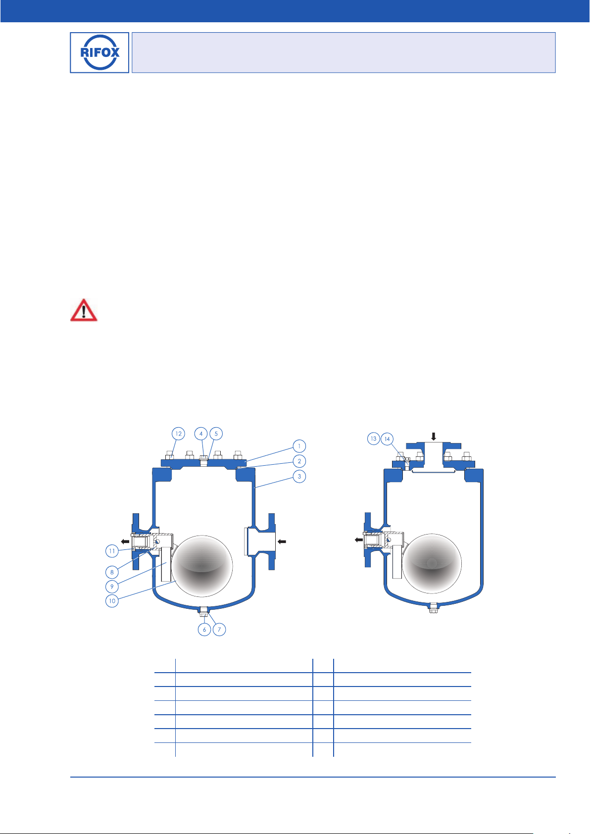
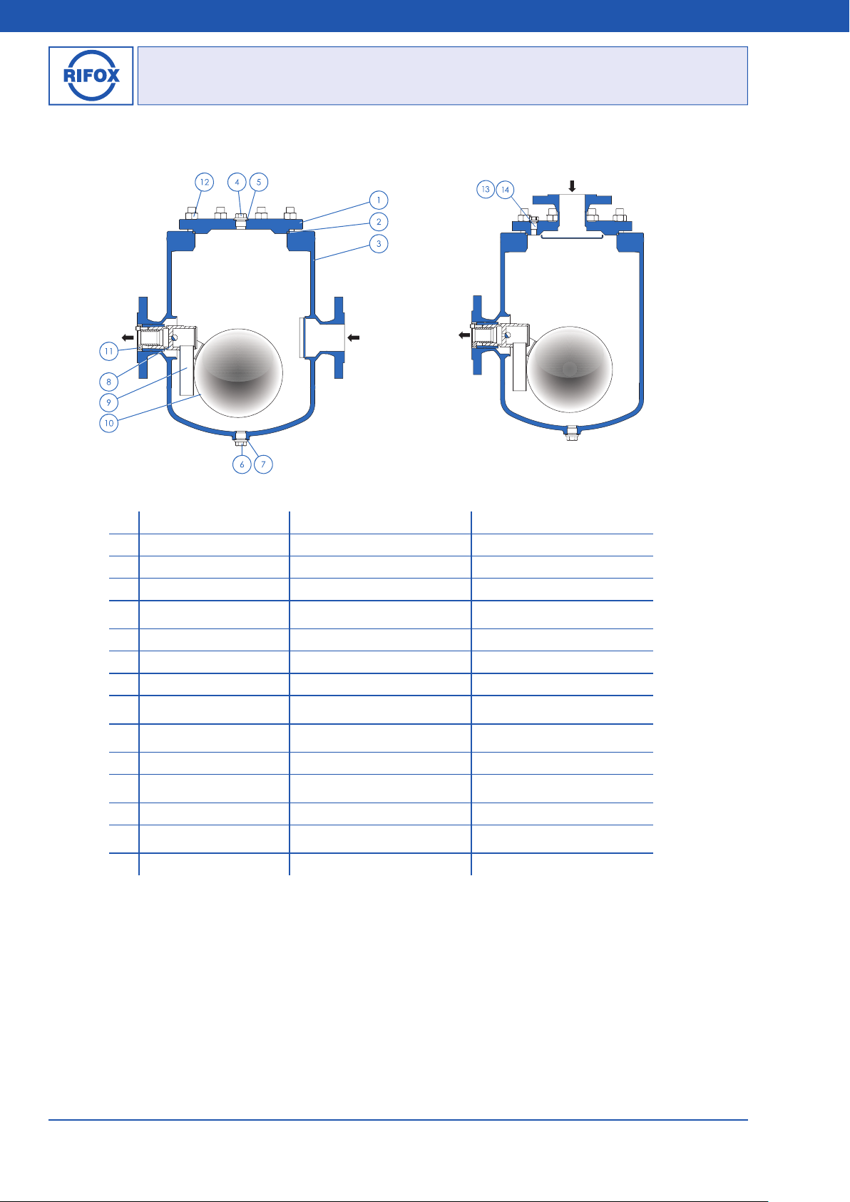
6.1.1 Float control unit with spherical float
■ The steam trap has to be depressurized. Shut off the system securely in front of and behind the steam trap.
■ Release any remaining pressure in the housing by loosening the control screw (4) by only a quarter turn.
■Dismantle the steam trap from the pipeline system. Loosen the flange connections and lift out of the pipeline carefully and
place on the floor.
Attention: The condensate trap weights from 70 up to 78kg depending on the connection sizes. Lifting device is required.
■Loosen the housing screws (12) evenly crosswise. Put down the housing cover (1). Attention: the housing cover weights
about 9 kg.
■The float control unit is dismantled with a centering aid that is inserted in the bushing provided with 2 slots. By turning
counterclockwise (3-4 turns) the bushing is screwed out of the control support body (9). The control unit is detached from
the seat cone by means of gentle blows with a hammer on the front end of centering aid.
■Screw out the bushing completely.
■Remove float control unit (8) through the cover opening.
6.1.2 Float control unit with oval float
■The steam trap has to be depressurized. Shut off the system securely in front of and behind the steam trap.
■Release any remaining pressure in the housing by loosening the control screw (4) by only a quarter turn.
■Dismantle the steam trap from the pipeline system. Loosen the flange connections and lift out of the pipeline carefully and
place on the floor.
Attention: The condensate trap weights from 70 up to 78kg depending on the connection sizes. Lifting device is required.
■Loosen the housing screws (12) evenly crosswise. Put down the housing cover (1). Attention: the housing cover weights
about 9 kg.
■Loosen the screws between float and fork by using a flat ring spanner.
■Remove the screws and the spring washer.
■Turn the oval float inside the housing and lift it out vertically.
■If only the float has to be replaced, continue with section 6.3.2 point 3.
■The supporting body with fork is dismantled with a centering aid that is inserted in the bushing provided with 2 slots. By
turning counterclockwise (3-4 turns), the bushing is screwed out of the control support body (9). The control is detached from
the seat cone by means of gentle blows with a hammer on the front end of centering aid.
■Screw out the bushing completely.
■Remove supporting body with fork through the cover opening.
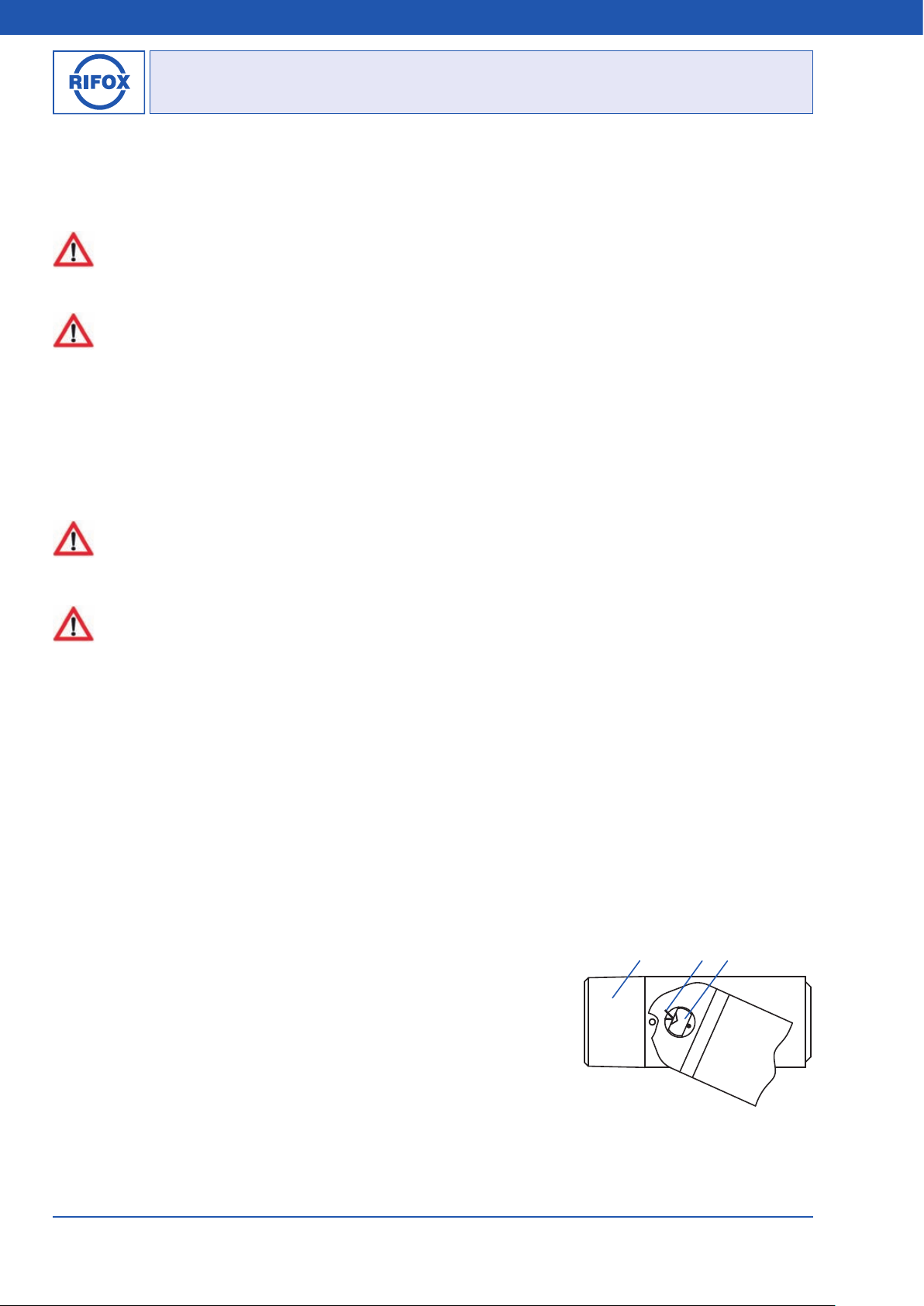
6.2 Disassembling, cleaning and assembling the float control (Picture 5)
■After removing the cotter pin (p), the rotary valve (v) can be simply pulled out
to the side.
■Clean the parts using, for example, benzine.
■Check the rotary valve (v) for wear along the sealing edge. If wear is detected,
the support body (b) together with the rotary valve (v) must be replaced. The
thorough leakage test must be carried out by RIFOX.
■During assembly ensure that the notch in the rotary valve (v) points to the
punch mark on the support body (b) and the cotter pin (p) is inserted and secured
again carefully.
■It must be possible to move the float up and down easily by hand.
bpv
Picture 5