RIGADO BMD-200-EVAL-S User manual

BMD-200-EVAL-UG-V1.4 Page 1 of 20
Rigado LLC
3950 Fairview Industrial Dr SE, Ste 100
Salem, Oregon 97302
866-6-RIGADO modules@rigado.com
www.rigado.com/modules
BMD-200 Evaluation Kit User Guide
This document describes the BMD-200 Evaluation Kit from Rigado.
This Evaluation Kit allows for stand-alone use of the BMD-200
module featuring the Nordic nRF51822 RF System on Chip (SoC).
The purpose of this guide to provide setup instructions for starting
development and to describe the hardware functionality of the
BMD-200 Evaluation Kit.
1.Overview
The BMD-200 Evaluation Kit is a versatile hardware platform that provides an easy jumping off point for
almost any Bluetooth 4.1 Low Energy project. The kit can be powered externally via USB or with a CR2032
coin cell battery for portable use. USB provides a programming and debug interface (J-Link or CMSIS-DAP), as
well as communication via a virtual COM port. Two user configurable buttons are available, as well as an RGB
LED, ambient light sensor, accelerometer, EEPROM, and a current sense resistor. There is also an on-board
reset button. Breakout headers allow easy access to all of the BMD-200 GPIO pins.
1.1. Key Features
BMD-200 Bluetooth 4.1 System on Module (SoM)
On-board programming and debug (J-Link or Drag-&-Drop/CMSIS-DAP)
Virtual COM port over USB
Full GPIO pin out of BMD-200
I2C 3-axis accelerometer (NXP MMA8652FC)
Ambient light sensor (Avago APDS-9005-020)
16kb SPI EEPROM (ON Semi CAT25160VI-GT3)
Buttons and LEDs for user interaction
32.768kHz Crystal
CR2032 battery holder
Downloaded from Arrow.com.

BMD-200 Evaluation Kit User Guide
August 10, 2016
BMD-200-EVAL-UG-V1.4 Page 2 of 20
Table of Contents
1. Overview ...............................................................................................................................................1
1.1. Key Features..........................................................................................................................................1
1.2. Useful Tools...........................................................................................................................................4
2. Hardware Kit..........................................................................................................................................4
3. Getting Started ......................................................................................................................................5
3.1. Evaluation Board with SEGGER J-Link.....................................................................................................5
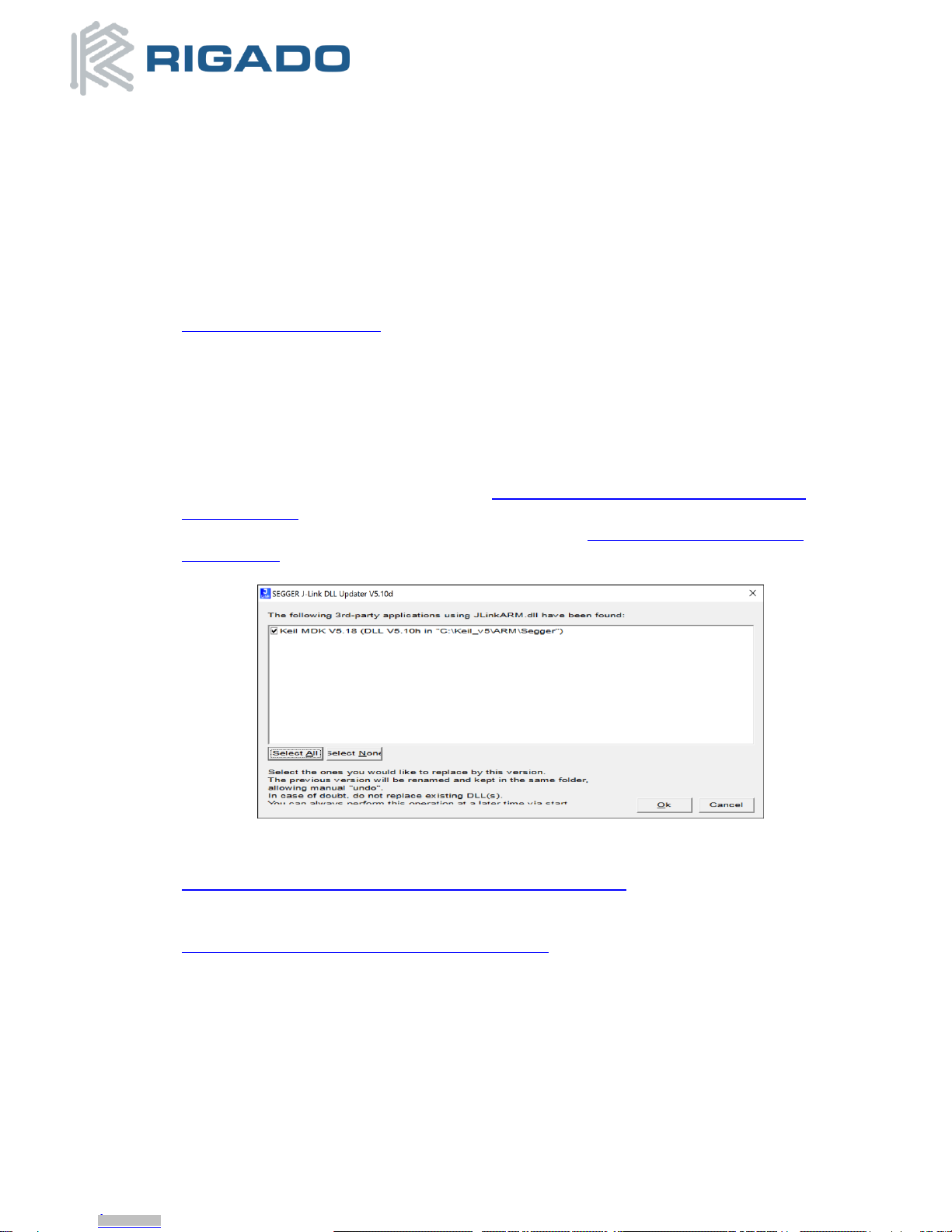
3.1.1. Set up tool chain...........................................................................................................................5
3.1.2. Connect BMD-200 Evaluation Kit to computer ..............................................................................5
3.1.3. Program BMD-200 Evaluation Kit with the S130 Soft Device .........................................................6
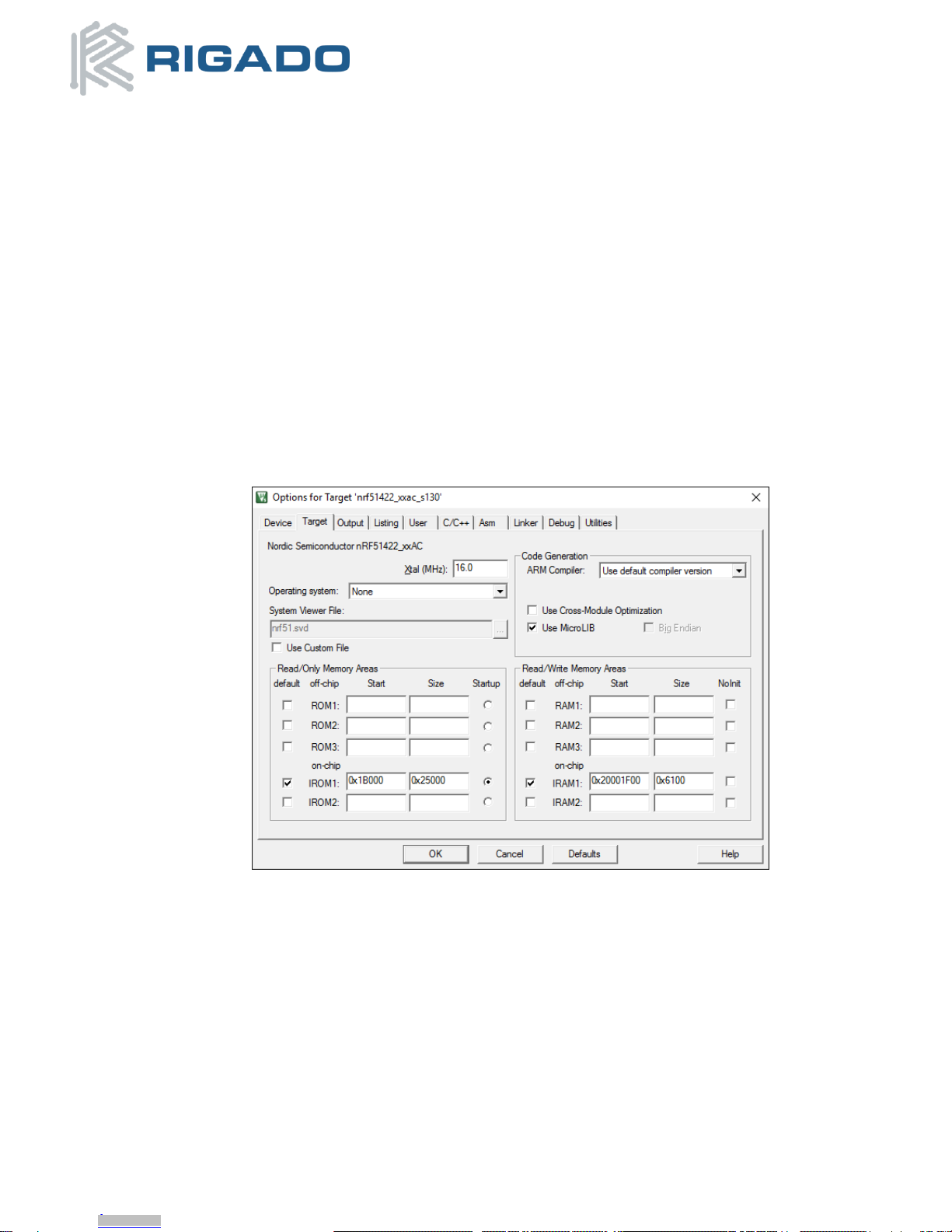
3.1.4. Set up the Application Project.......................................................................................................7
3.2. Evaluation Board with CMSIS-DAP (mbed).............................................................................................9
3.2.1. Connect BMD-200 Evaluation Kit to computer ..............................................................................9
3.2.2. Program BMD-200 Evaluation Kit (Drag and Drop) ........................................................................9
4. Hardware Description ..........................................................................................................................11
4.1. Power..................................................................................................................................................12
4.2. Buttons ...............................................................................................................................................12
4.3. LEDs ....................................................................................................................................................12
4.4. Virtual COM Port ................................................................................................................................. 13
4.5. Accelerometer.....................................................................................................................................13
4.6. SPI EEPROM.........................................................................................................................................14
4.7. Ambient Light Sensor...........................................................................................................................14
4.8. 32kHz Crystal Oscillator .......................................................................................................................14
4.9. Current Sensing Header.......................................................................................................................15
4.10. Headers...............................................................................................................................................16
4.11. GPIO Jumpers......................................................................................................................................17
5. Schematic ............................................................................................................................................18
6. BMD-200 Pinout...................................................................................................................................19
7. Life Support Policy ...............................................................................................................................20
8. Document History ................................................................................................................................20
9. Related Documents..............................................................................................................................20
Table of Figures
Figure 1 –BMD-200 Evaluation Board (Top View) .............................................................................................4
Figure 2 –Segger J-Link DLL Updater.................................................................................................................5
Figure 3 –nRFgo Studio SoftDevice Window.....................................................................................................6
Figure 4 –Keil Flash Tools Target Window ........................................................................................................7
Figure 5 –Keil Flash Tools C/C++ Window .........................................................................................................8
Figure 6 –Keil Flash Tools Debug Window ........................................................................................................8
Figure 7 –Keil Flash Tools Debug Settings Window ...........................................................................................9
Figure 8 –Pin Out and Functions.....................................................................................................................11
Figure 9 –Assembly Drawing (Top View).........................................................................................................11
Figure 10 –LED Driver Layout & Circuit...........................................................................................................13
Figure 11 –Accelerometer Layout................................................................................................................... 13
Figure 12 –LED Driver Layout .........................................................................................................................14
Figure 13 –Ambient Light Sensor Layout ........................................................................................................14
Figure 14 –32KHz Crystal Oscillator Layout.....................................................................................................15
Figure 15 –Current Sensing Header Layout .....................................................................................................15
Figure 16 –Header Layout ..............................................................................................................................16
Downloaded from Arrow.com.Downloaded from Arrow.com.

BMD-200 Evaluation Kit User Guide
August 10, 2016
BMD-200-EVAL-UG-V1.4 Page 3 of 20
Figure 17 –GPIO Jumper Layout .....................................................................................................................17
Figure 18 –BMD-200 Evaluation Board Schematic ..........................................................................................18
Figure 19 –BMD-200 Pin-out.......................................................................................................................... 19
Downloaded from Arrow.com.Downloaded from Arrow.com.Downloaded from Arrow.com.

BMD-200 Evaluation Kit User Guide
August 10, 2016
BMD-200-EVAL-UG-V1.4 Page 4 of 20
1.2. Useful Tools
Below is a list of tools that aid in development with the BMD-200 Bluetooth module. Not all tools will be
required depending on which software suite is used.
Tool
Description
Nordic nRFgo Studio
The Nordic software suite is used to program and configure Nordic nRF
devices. It supports programming of nRF51 application, bootloader, and
soft device. This tool uses the on board SEGGER J-Link programming
interface.
nRF Master Control
Panel for Android
A Nordic tool for Android devices to allow active scanning for Bluetooth
low energy devices and communication.
Keil MDK-ARM
Development Kit
A development environment designed for microcontroller applications
that enables development using the nRF51 SDK application and example
files.
SEGGER J-Link
Software
Software and documentation pack for the SEGGER J-Link interface
mbed Windows serial
port driver
Windows serial port driver for mbed version of Evaluation Board.
2.Hardware Kit
The two different BMD-200 Evaluation kits contains each of the following:
BMD-200-EVAL-S
1x BMD-200 Evaluation Board with on-board Segger JLink programmer
1x Micro-USB to USB-A cable
BMD-200-EVAL-M
1x BMD-200 Evaluation Board with on-board CMSIS-DAP(mbed) programmer
1x Micro-USB to USB-A cable
Figure 1 –BMD-200 Evaluation Board (Top View)
Downloaded from Arrow.com.Downloaded from Arrow.com.Downloaded from Arrow.com.Downloaded from Arrow.com.

BMD-200 Evaluation Kit User Guide
August 10, 2016
BMD-200-EVAL-UG-V1.4 Page 5 of 20
3.Getting Started
This section walks through how to set up and program the BMD-200 Evaluation Kit.
3.1. Evaluation Board with SEGGER J-Link
The BMD-200-Eval-S comes with a built in SEGGER J-Link programmer/debugger on board.
3.1.1. Set up tool chain
1. Download and install the latest Keil MDK-ARM development kit from
www.keil.com/arm/mdk.asp
a. Once the Keil MDK-ARM installation is complete, Keil will launch the Pack Installer.
The Keil Pack Installer manages software components for the various supported
microcontrollers.
b. The Pack Installer will automatically download any updates for the core ARM support.
c. Once these core packs are installed and up to date, close the Pack Installer
Note: As of Nordic Semiconductor SDK v11.0.0, Keil Packs are not supported. The full
SDK with the currently released SoftDevices is installed with step 4 below.
2. Download and install the nRFgo Studio from www.nordicsemi.com/eng/Products/2.4GHz-
RF/nRFgo-Studio
3. Download and install the latest Segger J-Link utilities from https://www.segger.com/jlink-
software.html. When prompted to overwrite the JLinkARM.dll file, select all of the listed
items and click OK:
Figure 2 –Segger J-Link DLL Updater
4. Download the latest Nordic Semiconductor nRF5 SDK from
http://developer.nordicsemi.com/nRF5_SDK/nRF5_SDK_v11.x.x. Extract the Zip file to a
working folder.
5. Download the BMD-200 Eval Kit Board Support File, custom_board.h, at
https://www.rigado.com/product/bmd-200-eval-kit/.Save the file to the following directory:
<unzipped SDK location>\examples\bsp\.
3.1.2. Connect BMD-200 Evaluation Kit to computer
1. Connect the BMD-200 Evaluation Board to a computer using the USB cable provided
2. The status LED, D6, will turn on indicating the board has power
3. After a few seconds the computer will recognize the Evaluation Board as a J-Link device
Downloaded from Arrow.com.Downloaded from Arrow.com.Downloaded from Arrow.com.Downloaded from Arrow.com.Downloaded from Arrow.com.

BMD-200 Evaluation Kit User Guide
August 10, 2016
BMD-200-EVAL-UG-V1.4 Page 6 of 20
3.1.3. Program BMD-200 Evaluation Kit with the S130 Soft Device
1. Open the Nordic nRFgo Studio application. In the ’Device Manager’ window, there will be a
device named Segger followed by serial number under ‘nRF51 development boards.’ Select
Segger and the device programming interface will appear in the main window
2. Click ‘Erase all’to clear the device of all current programmed software
3. Select the 'Program SoftDevice' tab in the pane on the right
4. Click ‘Browse…’ and navigate to the location of the extracted SoftDevice (<unzipped SDK
location>\components\softdevice\s130\hex. Select the SoftDevice hex file
5. Click program
6. After programming, nRFgo Studio should look similar to Figure 4.
Figure 3 –nRFgo Studio SoftDevice Window
7. Note the starting address of Region 1 for the application firmware (0x1B000 in this example)
8. Close nRFgo Studio.
Note: The S110 SoftDevice may be more suitable for the BMD-200-A with 16KB RAM
Downloaded from Arrow.com.Downloaded from Arrow.com.Downloaded from Arrow.com.Downloaded from Arrow.com.Downloaded from Arrow.com.Downloaded from Arrow.com.

BMD-200 Evaluation Kit User Guide
August 10, 2016
BMD-200-EVAL-UG-V1.4 Page 7 of 20
3.1.4. Set up the Application Project
1. Navigate to the location of the extracted examples from the SDK (typically <unzipped
location>\nRF5_SDK_11.0.0_89a8197\examples).
2. Select one of the examples that is labeled with “(nRF51 PCA10028)”and “s130”. The Heart
Rate Service Sample Application ((<unzipped SDK
location\ble_peripheral\ble_app_hrs\pca10028\s130\arm5_no_packs\) is a good place to
start. For starting on a custom application, using a template project is a good idea (such as
ble_app_template_s130_pca10028).
Note: If the S130 SoftDevice was selected in the previous section, select an example that is also
labeled for use with S130.
Likewise, if the S110 SoftDevice was selected in the previous section, select an example that is
also labeled for use with S110.
3. Open the project file (ble_app_hrs_s130_pca10028.uvprojx) to start the Keil IDE.
4. In the ‘Project’drop down menu click on ‘Options for Target ‘nrf51422_xxac_s130’’. In this
window go to the ‘Target’ tab make sure that the settings for the IROM starting address
matches the value from nRFgo Studio. Leave the other values at their default settings.
Figure 4 –Keil Flash Tools Target Window
Note:The memory locations in Figure 4 are based on the size of the S130 SoftDevice v2.0.0. If a
different SoftDevice is used, these values may need to be adjusted. The SoftDevice specification
documents contain the ROM and RAM requirements of each SoftDevice, see Nordic’s website.
Downloaded from Arrow.com.Downloaded from Arrow.com.Downloaded from Arrow.com.Downloaded from Arrow.com.Downloaded from Arrow.com.Downloaded from Arrow.com.Downloaded from Arrow.com.

BMD-200 Evaluation Kit User Guide
August 10, 2016
BMD-200-EVAL-UG-V1.4 Page 8 of 20
5. Go to the ‘C/C++’tab, and in the field marked ‘Define’change “BOARD_PCA10028”to
“BOARD_CUSTOM”as shown in Figure 6.
Figure 5 –Keil Flash Tools C/C++ Window
6. In the ‘Debug’tab of the same ‘Options for Target’window, select ‘J-LINK/J-TRACE Cortex’
from the upper right hand drop down menu then click ‘Settings.’The same 9 digit serial
number from the nRFgo program should be in the ‘SN’field to acknowledge Keil sees the
Evaluation Board (see figures 7 and 8).
Figure 6 –Keil Flash Tools Debug Window
Downloaded from Arrow.com.Downloaded from Arrow.com.Downloaded from Arrow.com.Downloaded from Arrow.com.Downloaded from Arrow.com.Downloaded from Arrow.com.Downloaded from Arrow.com.Downloaded from Arrow.com.

BMD-200 Evaluation Kit User Guide
August 10, 2016
BMD-200-EVAL-UG-V1.4 Page 9 of 20
Figure 7 –Keil Flash Tools Debug Settings Window
7. Build ( , ‘F7’) and download the example program to the Evaluation Board ( , ‘Flash’->
‘Download’).
8. Your BMD-200 Evaluation Board should now be running the example application.
9. If the Heart Rate Service example was loaded in step2 and 3, its functionality may be checked
with the “nRF Toolbox” app on iOS or Android. Run the app and select the heart rate monitor
(HRM). Make the connection to the “Nordic_HRM” device.
3.2. Evaluation Board with CMSIS-DAP (mbed)
The BMD-200-Eval-M comes with a built in CMSIS-DAP (mbed) programmer on board.
3.2.1. Connect BMD-200 Evaluation Kit to computer
1. Connect the BMD-200 Evaluation Board to a computer using the USB cable provided
2. The status LED, D6, will turn on indicating the board has power
3. After a few seconds the computer will recognize the board as a standard USB drive named
‘MBED’
3.2.2. Program BMD-200 Evaluation Kit (Drag and Drop)
1. Register for an mbed account at developer.mbed.org.
2. Go to http://developer.mbed.org/platforms/Nordic-nRF51822/ and add the Nordic nRF51822
platform to your compiler.
3. Import either the blinky app for the BMD-200 or the mbed library modified for the BMD-200
(replaces the “mbed” library).
4. Click ‘Compile’along the top toolbar in the mbed compiler page. When complete it will
automatically download hex file.
5. Drag and drop the downloaded hex file into the ‘MBED’drive. This will automatically program
the Evaluation Board. The status LED, D6, will flash while programming.
Downloaded from Arrow.com.Downloaded from Arrow.com.Downloaded from Arrow.com.Downloaded from Arrow.com.Downloaded from Arrow.com.Downloaded from Arrow.com.Downloaded from Arrow.com.Downloaded from Arrow.com.Downloaded from Arrow.com.

BMD-200 Evaluation Kit User Guide
August 10, 2016
BMD-200-EVAL-UG-V1.4 Page 10 of 20
6. The program will automatically run when programming is complete. If an error occurs, a file
called ‘fail.txt’ will be created on the ’MBED’ drive giving the reason for the failure.
Note: Keil and other design environments can program and debug the Evaluation Board using
the on-board CMSIS-DAP compatible programmer.
Note: The BMD-200 can be fully erased by holding down ‘Reset’ button for 5 seconds. After 5
seconds, status LED, D6, will flash faster while erasing. Once the erase procedure is complete,
status LED, D6, will return to solid, and communication LED, D5, will turn off.
Downloaded from Arrow.com.Downloaded from Arrow.com.Downloaded from Arrow.com.Downloaded from Arrow.com.Downloaded from Arrow.com.Downloaded from Arrow.com.Downloaded from Arrow.com.Downloaded from Arrow.com.Downloaded from Arrow.com.Downloaded from Arrow.com.

BMD-200 Evaluation Kit User Guide
August 10, 2016
BMD-200-EVAL-UG-V1.4 Page 11 of 20
4.Hardware Description
Figure 8 –Pin Out and Functions
RGB LED
BMD-200
Reset
Button
Breakout
Header
User
Button 1
User
Button 2
Micro-USB
Power,
Programming, &
Virtual COM
Breakout
Header
Current Sense
Header
Current Sense
Resistor
3-axis I2C
Accelerometer
Analog
Ambient Light
Sensor
16kb SPI
EEPROM
Figure 9 –Assembly Drawing (Top View)
Downloaded from Arrow.com.Downloaded from Arrow.com.Downloaded from Arrow.com.Downloaded from Arrow.com.Downloaded from Arrow.com.Downloaded from Arrow.com.Downloaded from Arrow.com.Downloaded from Arrow.com.Downloaded from Arrow.com.Downloaded from Arrow.com.Downloaded from Arrow.com.

BMD-200 Evaluation Kit User Guide
August 10, 2016
BMD-200-EVAL-UG-V1.4 Page 12 of 20
4.1. Power
The BMD-200 Evaluation Board has two possible power sources: the Micro-USB header and the coin cell
battery. These power sources are isolated from each other by default to allow both to be connected
simultaneously.
The USB +5V supplies the 3.3V LDO regulator, and the 3.3V connects to VSYS through a diode OR with
VBATT. VSYS is required for operating the BMD-200 and sensors on the Evaluation Board. The 5V rail
provides power for the programming interface only, and is only required when programming or
debugging. There are several options for configuring the power rails. Jumper J7 and J6 allow the user to
select the power source for the 5V and 3V rails. If running the Evaluation Board from the battery for long
periods of time, short the solder jumper, JBAT, together to bypass the diode and gain extra battery life. If
JBAT is shorted, the battery MUST be removed before connecting to USB power or it will damage the
battery.
4.2. Buttons
The Evaluation Board has three switches: Reset, User 1, and User 2. All buttons are active low; they will
connect to ground when pressed.
The Reset button has different behaviors based on the version of Evaluation Kit. On the BMD-200-EVAL-S
it is a true hard reset to the BMD-200; do not press this during programming/debugging as it may cause
the device to become unrecoverable. On the BMD-200-EVAL-M, the Reset button has three purposes. If
held while powering on the Evaluation Board, it will enter the mbed bootloader mode for updating the
mbed programmer. During normal operation the BMD-200-EVAL-M Reset button will perform a reset to
the BMD-200 if powered through USB, but if powered from the battery the Reset button has no function.
A long press (5 seconds) of the Reset button will perform a full erase of the BMD-200.
User Button is 1 connected to pin 23/P0.11, and User Button 2 is connected to pin 11/P0.00. The
nRF51822 pins should be configured with pull-up resistors for proper operation when using the user
buttons. The pins are also routed to the breakout headers.
4.3. LEDs
One user controllable RGB LED is provided on the Evaluation Board. The LED contains a red, green, and
blue LED in a single package with a common anode that is connected to VSYS. Each cathode is connected
to a separate GPIO pin on the BMD-200 through an N-FET. The N-FET inverts the logic so the LED enable
signals are active high. The red LED is connected to pin 12/P0.01, the green LED is connected to pin
5/P0.24, and the blue LED is connected to pin 6/P0.25. The red and blue LEDs are also routed to the
breakout headers.
Downloaded from Arrow.com.Downloaded from Arrow.com.Downloaded from Arrow.com.Downloaded from Arrow.com.Downloaded from Arrow.com.Downloaded from Arrow.com.Downloaded from Arrow.com.Downloaded from Arrow.com.Downloaded from Arrow.com.Downloaded from Arrow.com.Downloaded from Arrow.com.Downloaded from Arrow.com.

BMD-200 Evaluation Kit User Guide
August 10, 2016
BMD-200-EVAL-UG-V1.4 Page 13 of 20
Figure 10 –LED Driver Layout & Circuit
4.4. Virtual COM Port
A virtual COM port over USB is provided to communicate with the BMD-200. The VCOM_TX UART signal is
connected to pin 21/P0.09, and the VCOM_RX UART signal is connected to pin 22/P0.10. The nRF51288
should configure this UART to TX on P0.10 and RX on P0.09. There are also flow control pins for the UART;
VCOM_CTS is connected to pin 14/P0.03, VCOM_RTS is connected to pin 13/P0.02. The nRF51288 should
configure this UART to RTS on P0.03 and CTS on P0.02. Flow control is always enabled for the BMD-200-
EVAL-S.
Communication LED, D5, will turn on during virtual COM port activity.
4.5. Accelerometer
The BMD-200 Evaluation Board comes with an on board 3-Axis Accelerometer that communicates over
I2C. There is one programmable interrupt request line from the accelerometer to allow for interrupt flags
on events, such as: tap-detect, motion, free-fall, and FIFO-threshold. For pin connection to BMD-200 see
section 4.10 Headers. The Accelerometer is a NXP MMA8652, for more information visit www.nxp.com.
Figure 11 –Accelerometer Layout
Downloaded from Arrow.com.Downloaded from Arrow.com.Downloaded from Arrow.com.Downloaded from Arrow.com.Downloaded from Arrow.com.Downloaded from Arrow.com.Downloaded from Arrow.com.Downloaded from Arrow.com.Downloaded from Arrow.com.Downloaded from Arrow.com.Downloaded from Arrow.com.Downloaded from Arrow.com.Downloaded from Arrow.com.

BMD-200 Evaluation Kit User Guide
August 10, 2016
BMD-200-EVAL-UG-V1.4 Page 14 of 20
4.6. SPI EEPROM
The BMD-200 Evaluation Board has one 16kb SPI EEPROM. It is not connected to the BMD-200 by default;
to enable the interface the solder bridge must be reconfigured, see section 4.11 GPIO Jumpers. The
EEPROM is a CAT25160VI-GT3 from On Semiconductor, for more information visit www.onsemi.com.
Figure 12 –LED Driver Layout
4.7. Ambient Light Sensor
The on-board Ambient Light Sensor is a current output sensor. Load resistor R11 (4.75kΩ) to convert the
current output into a voltage for measurement by the BMD-200 ADC on pin P0.06. The light sensitivity
range is set to have a linear response across most light conditions. The output range of the sensor is 0V to
~2.1V. Configuring the BMD-200 ADC to use the internal band-gap reference with input prescaling set to
2/3 will enable measurement for most of the usable light range with the greatest resolution. The Ambient
Light Sensor is an APDS-9005 from Avago, for more information visit www.avagotech.com.
Figure 13 –Ambient Light Sensor Layout
4.8. 32kHz Crystal Oscillator
The BMD-200 Evaluation Board has a 32.768kHz Crystal Oscillator connected to the BMD-200 by default.
This external oscillator is not required for operation, as an internal Ring Oscillator is also available. To
disconnect crystal oscillator, see section 4.11 GPIO Jumpers.
Downloaded from Arrow.com.Downloaded from Arrow.com.Downloaded from Arrow.com.Downloaded from Arrow.com.Downloaded from Arrow.com.Downloaded from Arrow.com.Downloaded from Arrow.com.Downloaded from Arrow.com.Downloaded from Arrow.com.Downloaded from Arrow.com.Downloaded from Arrow.com.Downloaded from Arrow.com.Downloaded from Arrow.com.Downloaded from Arrow.com.

BMD-200 Evaluation Kit User Guide
August 10, 2016
BMD-200-EVAL-UG-V1.4 Page 15 of 20
Figure 14 –32KHz Crystal Oscillator Layout
4.9. Current Sensing Header
The current sensing header, JCUR, allows for power consumption measurement of the BMD-200. The
three pin, .1” pitch header has two pins connected across a 1 ohm current sense resistor powering the
BMD-200, and the third pin to ground. To measure current consumption use a multimeter or other
precision voltage measurement device to measure voltage drop across pins one and two. Measuring the
current directly can also be accomplished by removing R20 and using a current meter in series with pins
one and two. The default hardware configuration does not require any modification of the current sense
header for the BMD-200 Evaluation Board to perform properly.
Note: Only current into the BMD-200 VCC pin flows through R20. Current sinked into GPIO pins and
peripheral power usage is not accounted for.
Figure 15 –Current Sensing Header Layout
Downloaded from Arrow.com.Downloaded from Arrow.com.Downloaded from Arrow.com.Downloaded from Arrow.com.Downloaded from Arrow.com.Downloaded from Arrow.com.Downloaded from Arrow.com.Downloaded from Arrow.com.Downloaded from Arrow.com.Downloaded from Arrow.com.Downloaded from Arrow.com.Downloaded from Arrow.com.Downloaded from Arrow.com.Downloaded from Arrow.com.Downloaded from Arrow.com.

BMD-200 Evaluation Kit User Guide
August 10, 2016
BMD-200-EVAL-UG-V1.4 Page 16 of 20
4.10. Headers
The connectors `A1` and `B1` break out the IO signals from the BMD-200 to two 0.1” pitch ten pin headers.
To use a pin’s alternate functions listed below, see section 4.11 GPIO Jumpers.
Connector A1
Header
Pin
Pin
Name
BMD-
200 Pin
nRF51
Port
Default Function
Alternate Function
1
VUSB
-
-
+5.0V USB Power
2
VSYS
-
-
+3.3V System Power
3
P0.27
9
P0.27
32kHz Oscillator P2
GPIO
4
P0.26
11
P0.26
32kHz Oscillator P1
GPIO
5
P0.25
6
P0.25
Blue LED ~PWM
6
P0.24
5
P0.24
Green LED ~PWM
7
P0.11
23
P0.11
User Switch 1
8
P0.10
22
P0.10
UART VCOM RX
9
P0.09
21
P0.09
UART VCOM TX
10
GND
-
-
System Ground
Connector B1
Header
Pin
Pin
Name
BMD-
200 Pin
nRF51
Port
Default Function
Alternate Function
1
VSYS
-
-
+3.3V System
Power
2
P0.08
20
P0.08
Accel I2C SDA
3
P0.06
17
P0.06
Ambient light ADC
4
P0.05
16
P0.05
Accel I2C SCL
5
P0.04
15
P0.04
Accel Interrupt 1
6
P0.03
14
P0.03
UART VCOM RTS
EEPROM SPI ~CS
7
P0.02
13
P0.02
UART VCOM CTS
EEPROM SPI MISO
8
P0.01
12
P0.01
Red LED ~PWM
EEPROM SPI MOSI
9
P0.00
11
P0.00
User Switch 2
EEPROM SPI CLK
10
GND
-
-
System Ground
Figure 16 –Header Layout
Downloaded from Arrow.com.Downloaded from Arrow.com.Downloaded from Arrow.com.Downloaded from Arrow.com.Downloaded from Arrow.com.Downloaded from Arrow.com.Downloaded from Arrow.com.Downloaded from Arrow.com.Downloaded from Arrow.com.Downloaded from Arrow.com.Downloaded from Arrow.com.Downloaded from Arrow.com.Downloaded from Arrow.com.Downloaded from Arrow.com.Downloaded from Arrow.com.Downloaded from Arrow.com.

BMD-200 Evaluation Kit User Guide
August 10, 2016
BMD-200-EVAL-UG-V1.4 Page 17 of 20
4.11. GPIO Jumpers
There are many solder bridge jumpers on the board available for customizing the BMD-200 operation and
pin-out. By default, all two-pin jumpers are connected by a small copper trace between the pads that can
be cut to disconnect the jumpers. All three-pin jumpers have the center common pad connected to the
BMD-200 GPIO, and are connected by default to one of the two pads with a copper trace. The three pin
headers can likewise be disconnected by cutting the copper trace, and connected to the alternate pad
with solder. The GPIO jumpers bridge between the GPIO pin on the BMD-200 and the default interface on
the Evaluation Board. The headers are connected to the GPIO side of the jumper, so even if the jumpers
are disconnected the headers still connect to the BMD-200. To use any pin as an external GPIO, it is
recommended to disconnect the corresponding jumper to prevent interference from connected circuitry.
The SPI EEPROM is the only device that requires modifying jumpers to communicate with the BMD-200.
To connect this, the corresponding jumpers must be disconnected from the default configuration and
solder bridged to the alternate pads. See the table below for jumper connectivity.
Jumper
BMD-200
GPIO
Default Connection
Alternate
Connection
J00
P0.00
SW2
EE_CLK
J01
P0.01
LED_R
EE_MOSI
J02
P0.02
VCOM_RTS
EE_MISO
J03
P0.03
VCOM_CTS
EE_CS
J04
P0.04
ACCEL_INT1
-
J05
P0.05
ACCEL_SCL
-
J06
P0.06
AMBIENT_LIGHT
-
J08
P0.08
ACCEL_SDA
-
J09
P0.09
VCOM_TX
-
J10
P0.10
VCOM_RX
-
J11
P0.11
SW1
-
J24
P0.24
LED_G
-
J25
P0.25
LED_B
-
J26
P0.26
32kHz Oscillator P1
GPIO
J27
P0.27
32kHz Oscillator P2
GPIO
Figure 17 –GPIO Jumper Layout
Downloaded from Arrow.com.Downloaded from Arrow.com.Downloaded from Arrow.com.Downloaded from Arrow.com.Downloaded from Arrow.com.Downloaded from Arrow.com.Downloaded from Arrow.com.Downloaded from Arrow.com.Downloaded from Arrow.com.Downloaded from Arrow.com.Downloaded from Arrow.com.Downloaded from Arrow.com.Downloaded from Arrow.com.Downloaded from Arrow.com.Downloaded from Arrow.com.Downloaded from Arrow.com.Downloaded from Arrow.com.

BMD-200 Evaluation Kit User Guide
August 10, 2016
BMD-200-EVAL-UG-V1.4 Page 18 of 20
5.Schematic
Figure 18 –BMD-200 Evaluation Board Schematic
Downloaded from Arrow.com.Downloaded from Arrow.com.Downloaded from Arrow.com.Downloaded from Arrow.com.Downloaded from Arrow.com.Downloaded from Arrow.com.Downloaded from Arrow.com.Downloaded from Arrow.com.Downloaded from Arrow.com.Downloaded from Arrow.com.Downloaded from Arrow.com.Downloaded from Arrow.com.Downloaded from Arrow.com.Downloaded from Arrow.com.Downloaded from Arrow.com.Downloaded from Arrow.com.Downloaded from Arrow.com.Downloaded from Arrow.com.

BMD-200 Evaluation Kit User Guide
August 10, 2016
BMD-200-EVAL-UG-V1.4 Page 19 of 20
6.BMD-200 Pinout
Top View
Figure 19 –BMD-200 Pin-out
Pin description
Name
Pin
Direction
Description
P0.24
5
In/Out
GPIO
P0.25
6
In/Out
GPIO
P0.26
8
In/Out
GPIO/AIN1/XTAL2 (32.768kHz)
P0.27
9
In/Out
GPIO/AIN0/XTAL1(32.768kHz)
P0.00
11
In/Out
GPIO/AREF0
P0.01
12
In/Out
GPIO/AIN2
P0.02
13
In/Out
GPIO/AIN3
P0.03
14
In/Out
GPIO/AIN4
P0.04
15
In/Out
GPIO/AIN5
P0.05
16
In/Out
GPIO/AIN6
P0.06
17
In/Out
GPIO/AIN7/AREF1
P0.08
20
In/Out
GPIO
P0.09
21
In/Out
GPIO
P0.10
22
In/Out
GPIO
P0.11
23
In/Out
GPIO
SWDIO
24
In/Out
SWD IO/ RESET
SWCLK
25
In
SW Clock 1
VCC
18
Power
+2.1 to +3.6VDC input 2
GND
1, 2, 3, 4, 7, 10, 19,
26, (27, 28 opt.)
Power
Electrical Ground
Note 1: SWDCLK has an internal 12 kΩ pull-down resistor.
Note 2: An external capacitor for VCC is not strictly required, however using a 1µF - 4.7µF
ceramic capacitor is recommended.
Downloaded from Arrow.com.Downloaded from Arrow.com.Downloaded from Arrow.com.Downloaded from Arrow.com.Downloaded from Arrow.com.Downloaded from Arrow.com.Downloaded from Arrow.com.Downloaded from Arrow.com.Downloaded from Arrow.com.Downloaded from Arrow.com.Downloaded from Arrow.com.Downloaded from Arrow.com.Downloaded from Arrow.com.Downloaded from Arrow.com.Downloaded from Arrow.com.Downloaded from Arrow.com.Downloaded from Arrow.com.Downloaded from Arrow.com.Downloaded from Arrow.com.

BMD-200 Evaluation Kit User Guide
August 10, 2016
BMD-200-EVAL-UG-V1.4 Page 20 of 20
7.Life Support Policy
This product is not designed to be used in a life support device or system, or in applications where there is
potential for a failure or malfunction to, directly or indirectly, cause significant injury. By using this product in
an application that poses these risks, such as described above, the customer is agreeing to indemnify Rigado
for any damages that result.
8.Document History
Revision
Date
Changes / Notes
0.1
12/26/14
Initial document draft
1.0
1/13/15
Initial release
1.1
2/5/15
Updated for formatting, clarity
1.2
5/29/15
Updated for nRF51 SDK v8.1
1.3
3/22/16
Updated to show use of S130, updated to reflect changes in Nordic SDK
1.4
8/10/16
Updated logo and address on first page
9.Related Documents
Rigado Documents:
BMD-200-DS: Module Datasheet
BMD-200-AN-1: MAC Address Provisioning
Nordic Semiconductor Documents:
nRF51822-PS: nRF51822 Product Specification
nRF51 RM: nRF51 Series Reference Manual
S110-SDS: nRF51822 S110 SoftDevice Specification
S120-SDS: nRF51822 S120 SoftDevice Specification
S130-SDS: nRF51822 S130 SoftDevice Specification
Downloaded from Arrow.com.Downloaded from Arrow.com.Downloaded from Arrow.com.Downloaded from Arrow.com.Downloaded from Arrow.com.Downloaded from Arrow.com.Downloaded from Arrow.com.Downloaded from Arrow.com.Downloaded from Arrow.com.Downloaded from Arrow.com.Downloaded from Arrow.com.Downloaded from Arrow.com.Downloaded from Arrow.com.Downloaded from Arrow.com.Downloaded from Arrow.com.Downloaded from Arrow.com.Downloaded from Arrow.com.Downloaded from Arrow.com.Downloaded from Arrow.com.Downloaded from Arrow.com.
This manual suits for next models
2
Table of contents
Other RIGADO Motherboard manuals