PerfecTron INS8365B User manual

Version 1.0
INS8365B
Intel® Coffee Lake-R 8/9th Processor with
Q370 Chipset Mini-ITX
www.perfectron.com

www.perfectron.com
1
Safety Information
Electrical safety
To prevent electrical shock hazard, disconnect the power cable from the electrical outlet before
relocating the system.
When adding or removing devices to or from the system, ensure that the power cables for the
devices are unplugged before the signal cables are connected. If possible, disconnect all power
cables
from the existing system before you add a device.
Before connecting or removing signal cables from the motherboard, ensure that all power cables
are
unplugged.
Seek professional assistance before using an adapter or extension cord. These devices could
interrupt the grounding circuit.
Make sure that your power supply is set to the correct voltage in your area.
If you are not sure about the voltage of the electrical outlet you are using, contact your local
power company.
If the power supply is broken, do not try to fix it by yourself. Contact a qualified service
technician or your local distributor.
Operation safety
Before installing the motherboard and adding devices on it, carefully read all the manuals that
came with the package.
Before using the product, make sure all cables are correctly connected and the power cables are
not
damaged. If you detect any damage, contact your dealer immediately.
To avoid short circuits, keep paper clips, screws, and staples away from connectors, slots, sockets
and
circuitry.
Avoid dust, humidity, and temperature extremes. Do not place the product in any area where it may
become wet.
Place the product on a stable surface.
If you encounter any technical problems with the product, contact your local distributor
Statement
All rights reserved. No part of this publication may be reproduced in any form or by any means,
without prior written permission from the publisher.
All trademarks are the properties of the respective owners.
All product specifications are subject to change without prior notice

www.perfectron.com
2
RoHS Compliance
Perfectron RoHS Environmental Policy and Status Update
Perfectron is a global citizen for building the digital infrastructure. We are committed to
providing green products and services, which are compliant with
European Union RoHS (Restriction on Use of Hazardous Substance in Electronic Equipment) directive
2011/65/EU, to be your trusted green partner and to protect our environment.
In order to meet the RoHS compliant directives, Perfectron has established an engineering and
manufacturing task force to implement the introduction of green products. The task force will ensure that
we follow the standard Perfectron development procedure and that all the new RoHS components and new
manufacturing processes maintain the highest industry quality levels for which Perfectron are renowned.
The model selection criteria will be based on market demand. Vendors and suppliers will ensure that all
designed components will be RoHS compliant

www.perfectron.com
3
Revision History
Revision Date (yyyy/mm/dd) Changes
V1.0 2022/05/04 First release
Packing List
Item
Description Q’ty
1 INS8365B 1
2 CD(Drivier + User’s manual) 1
If any of the above items is damaged or missing, please contact your
local distributor.

www.perfectron.com
4
Table of Contents
Safety Information .............................................................................................................................................................. 1
Electrical safety .................................................................................................................................................................. 1
Operation safety ................................................................................................................................................................ 1
Statement ......................................................................................................................................................................... 1
RoHS Compliance ................................................................................................................................................................ 2
Revision History .................................................................................................................................................................. 3
Packing List ......................................................................................................................................................................... 3
Chapter 1 : Product Introduction ........................................................................................................................................ 6
1.1 Specifications ............................................................................................................................................................... 6
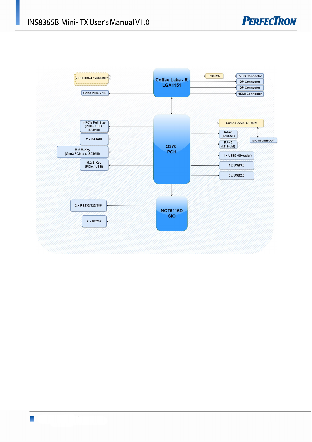
1.2 Block Diagram .............................................................................................................................................................. 8
1.3 Board Placement .......................................................................................................................................................... 9
Chapter 2 : Jumpers and Connectors Loacation ................................................................................................................ 10
2.1 Jumpers And Connectors List ........................................................................................................................................ 10
2.2 Jumper Settings .......................................................................................................................................................... 11
Chapter 3: AMI BIOS UTILITY ............................................................................................................................................. 15
3.1 Staring ....................................................................................................................................................................... 15
3.2 Navigation Keys .......................................................................................................................................................... 15
3.3 Main Page .................................................................................................................................................................. 16
3.4 Advance Page ............................................................................................................................................................. 18
3.4.1 CPU Configuration ............................................................................................................................................... 20
3.4.2 Trusted Computing(Optional) ............................................................................................................................... 22
3.4.3 ACPI Settings ....................................................................................................................................................... 23
3.4.4 SMART Settings ................................................................................................................................................... 24
3.4.5 Super IO Configuration ........................................................................................................................................ 24
3.4.6 Serial Port 1 Configuration .................................................................................................................................... 25
3.4.7 Serial Port 2 Configuration .................................................................................................................................... 26
3.4.8 Serial Port 3 Configuration .................................................................................................................................... 27
3.4.9 Serial Port 4 Configuration .................................................................................................................................... 28
3.4.10 Hardware Monitor ........................................................................................................................................ 29
3.4.11 RTC Wake Settings ........................................................................................................................................ 30
3.4.12 Network Stack Configuration ......................................................................................................................... 31
3.4.13 NVMe Configuration ..................................................................................................................................... 32
3.5 Chipset Page .............................................................................................................................................................. 32

www.perfectron.com
5
3.5.1 System Agnet (SA) Configuration ............................................................................................................................ 33
3.5.2 Graphics Configuration ......................................................................................................................................... 33
3.5.3 PCH-IO Configuration ........................................................................................................................................... 34
3.5.4 SATA And RST Configuration .................................................................................................................................. 35
3.6 Security Page .............................................................................................................................................................. 36
3.6.1 HDD Security ........................................................................................................................................................ 37
3.6.2 Secure Boot .......................................................................................................................................................... 38
3.6.3 Key Management(Secure Boot Mode set to Custom) ................................................................................................. 39
3.6.4 BIOS Update ......................................................................................................................................................... 42
3.7 Boot Page .................................................................................................................................................................. 43
3.7.1 (List Boot Device Type) Drive BBS Priorities ............................................................................................................... 45
3.8 Save & Exit Page .......................................................................................................................................................... 46
3.9 Recover Page (Active For Secur Flash Update Only) ......................................................................................................... 47

www.perfectron.com
6
Chapter 1 : Product Introduction
1.1 Specifications
System
CPU 9th & 8th Gen Intel Coffee Lake LGA1151 Socket Processor,
Core i7/i5/i3 6-core TDP Max. 95W, Core i9 8-core TDP Max 35W
System Memory DDR4 2666MHz, 2 x 260-pin SO-DIMM, Max. 64GB (Non-ECC)
Chipset Intel Q370 (Support RAID 0 / 1) support vPro
Graphics Intel® HD Graphics
I/O Chipset Nuvoton NCT6116D
TPM TPM Header
BIOS AMI BIOS / 256 Mbit SPI
H/W Monitor Temperature Monitor / Voltage Monitor / Fan Monitor
Watchdog Timer 1~255 steps by software program
Expansion
M.2 1 x M.2 2230 E key(PCIe / USB) / 1 x M.2 2260 / 2280 M key (Gen3 PCIeX4, SATAIII)
Mini PCie 1 x Mini PCIe Full size (PCIe / USB / SATAIII)
PCIe Slot 1 x PCIe 3.0 X16 slot
Display
HDMI Up to 4K (4096 x 2160) @30 Hz
Dsiplayport Up to 4K (4096 x 2304) @60 Hz
LVDS Up to 1920 x 1200 @60 Hz
Ethernet
Chipset Intel® I219-LM Giga LAN + Intel® I210-AT Giga LAN
Audio
Codec Realtek® ALC662
Rear I/O
USB 4 x USB 3.0
Display I/O 1 x HDMI 1.4 / 2 x DisplayPort 1.2
Audio I/O 1 x Mic-in / 1 x Line-out
LAN 2 x RJ-45
Power 1 x DIN – 4pin DC Jack

www.perfectron.com
7
Internal I/O
Storage 2 x SATAIII
USB 5 x USB 2.0
Display I/O 1 x LVDS / 1 x Backlight Connector
Audio I/O 1 x Speaker 2W
Serial Port 4 x RS232 (two supports RS232/422/485 select by BIOS)
GPIO 1 x MiAPI Header (Programmable)
Fan 1 x 4-pin CPU Fan Header / 1 x 4-pin System Fan Header
Power 1 x ATX 4-pin Power Connector, 1 x AT / ATX Mode Select Jumper
Others 1 x Front Audio Header (Mic-in / Line-out), 1 x CMOS Jumper,
1 x panel power select header, 1 x backlight power select header,
1x buzzer header
Environmental
Form Factor Mini ITX
Power Type DC-IN 12V DIN 4-pin connector / ATX 4pin 12V
Dimension 170 mm x 170mm
Operating TEMP. ET : -20 ~ 70°C
UT : -40 ~ 85°C
Storage TEMP. -40 ~ 85°C (-40 ~185°F)
Relative Hum. 10% ~ 95% R/H (Non-condensing)
Standard Compliance
Standart Compliance
CE / FCC
OS
OS Support Windows®10 64-bit
Linux(Support by request)

www.perfectron.com
8
1.2 Block Diagram

www.perfectron.com
9
1.3 Board Placement

www.perfectron.com
10
Chapter 2 : Jumpers and Connectors Loacation
2.1 Jumpers And Connectors List
Label
Function
1 ATX 4pin
2 PCIe x16 Slot
3 System Fan Header
4 CPU Socket
5 LVDS Backlight Header
6 Dual USB2.0 header
7 Panel Power Jumper
8 LVDS Connector
9 RS232 Header
10 RS232/422/485 Header
11 RS232/422/485 Header
12 RS232 Header
13 MiAPI Header
14 SATA Connector
15 SATA Connector
16 Internal Speaker Header
17 Front Audio Header
18 TPM Header
19 CPU FAN
20 AT/ATX Mode Jumper
21 Clear CMOS Header
22 USB2.0 Header
23 Dual USB2.0 header
24 Front Panel Header
25 SATA Power Header
26 DDR4 SO-DIMM Socket
27 mPCIe Slot
28 M.2 2230 E-Key Slot
29 M.2 2280 M-Key Slot

www.perfectron.com
11
2.2 Jumper Settings
Front Panel Header
PIN
DEFINITION PIN
DEFINITION
1
HDD_POWER_LED
2
POWER_LED_MAIN
3
HDD_LED# 4
POWER_LED_ALT
5
GND 6
POWER_SWITCH#
7
RESET_SWITCH#
8
GND
9
+5V_DC 10
Key(no pin)
LVDS Connector
PIN
DEFINITION
PIN
DEFINITION
1
VCC3
2
Panel Power
3
VCC3
4
Panel Power
5
LVDS_DDC_SCL
6
LVDS_DDC_S
DA
7
GND (CABLE_ID1)
8
GND
9
LVDS0_LINK1_CON_DP
10
LVDS0_LINK0_CON_DP
11
LVDS0_LINK1_CON_DN
12
LVDS0_LINK0_CON_DN
13
CABLE_ID2 (reserved)
14
CABLE_ID3 (reserved)
15
LVDS0_LINK3_CON_DP
16
LVDS0_LINK2_CON_DP
17
LVDS0_LINK3_CON_DN
18
LVDS0_LINK2_CON_DN
1
9
GND
20
GND
21
LVDS1_LINK1_CON_DP
22
LVDS1_LINK0_CON_DP
23
LVDS1_LINK1_CON_DN
24
LVDS1_LINK0_CON_DN
25
GND
26
GND
27
LVDS1_LINK3_CON_DP
28
LVDS1_LINK2_CON_DP
29
LVDS1_LINK3_CON_DN
30
LVDS1_LINK2_CON_DN
31
GND
32
GND
33
LVDS1_CLK_CON_DP
34
LVDS0_CLK_CON_DP
35
LVDS1_CLK_CON_DN
36
LVDS0_CLK_CON_DN
37
GND
38
GND
39
+12V
40
+12V
LVDS Backlight Header
PIN
DEFINITION
1
LVDS_BKTEN_R
2
LVDS_PWM
3
BKLT_PWR (12v)
4
BKLT_PWR (12v)
5
GND
6
GND
7
BRIGHT_UP
-
8
BRIGHT_DOWN
-

www.perfectron.com
12
Dual USB2.0 Header
PIN
DEFINITION
PIN
DEFINITION
1
5V_USB
2
5V_USB
3
Data (negative)
4
Data (negative)
5
Data (positive)
6
Data (positive)
7
GND
8
GND
9
Key (no pin)
10
No Connect
USB2.0 Header
PIN
DEFINITION
1
5V_USB
2
Data
(negative)
3
Data (positive)
4
GND
5
Key (no pin)
Front Audio Header
PIN
DEFINITION
PIN
DEFINITION
1
MIC
2
AUD_GND
3
MIC_BIAS
4
Presence
5
FP_OUT_R
6
AUD_SENSE_MIC_FP
7
FIO_SENSE
8
Key
(no pin)
9
FP_OUT_L
10
AUD_SENSE_HP
Internal Speaker Header
PIN
DEFINITION
1
Front_L-
2
Front_L+
3
Front_R+
4
Front_R-
Serial Port Pin-Out
PIN
DEFINITION
1
DCD
2
RXD#
3
TXD#
4
DTR
5
GND
6
DSR
7
RTS
8
CTS
9
RI
CPU FAN Header
PIN
DEFINITION
1
GND
2
+12V

www.perfectron.com
13
3
CPU_FAN_TACH
4
CPU_FAN_CTRL
Clear CMOS Header
SATA Power Header
PIN
DEFINITION
1
VCC3
2
GND
3
VCC3
4
GND
5
+12V
Panel Power Option
PIN
DEFINITION
1-2
Clear CMOS
2-3
Normal(Default)
PIN
DEFINITION
PIN
DEFINITION
1
Key(no pin)
2
3.3V
3
12V
4
LCD_VCC
5 Key(no pin)
6 5V
3.3V(Default)
5V
12V

www.perfectron.com
14
MiAPI Header
PIN
DEFINITION
PIN
DEFINITION
1
MAPI_GPIO1
2 VCC
3
MAPI_GPIO
2
4
MAPI_GPIO
6
5
MAPI_GPIO
3
6
MAPI_GPIO
7
7
MAPI_GPIO
4
8
MAPI_GPIO
8
9
MAPI_GPIO
5
10
MAPI_GPIO
9
11
WD_Time
12
MAPI_GPIO
10
13
Power Button
14
SMBUS_DATA
15
UART_TX
16
SMBUS_CLK
17
UART_RX
18
5VSB
19
GND
20
N/A
TPM Header
PIN
DEFINITION
1
VSB_3V3
2
TPM_CS2
3
TPM_MISO
4
Key(no pin)
5
TPM_MOSI
6
PLTRST_N
7
PRIQ_N
8
GND
9
N/A
10
TPM_CLK
11
N/A
12
TPM_DET
13
N/A
14
VCC3_TPM
AT/ATX Mode Jumper
PIN
DEFINITION
1-2
AT Mode
2-3
ATX Mode(Default)

www.perfectron.com
15
Chapter 3: AMI BIOS UTILITY
This chapter provides users with detailed descriptions on how to set up a basic system
configuration through the AMI BIOS setup utility.
3.1 Staring
To enter the setup screens, perform the following steps:
• Turn on the computer and press the <Del> key immediately.
• After the <Del> key is pressed, the main BIOS setup menu displays. Other setup screens
can be accessed from the main BIOS setup menu, such as the Chipset and Power menus.
3.2 Navigation Keys
The BIOS setup/utility uses a key-based navigation system called hot keys. Most of the BIOS
setup utility hot keys can be used at any time during the setup navigation process.
Some of the hot keys are <F1>, <F10>, <Enter>, <ESC>, and <Arrow> keys.
Left/Right The Left and Right <Arrow> keys moves the cursor to select a
menu.
Up/Down The Up and Down <Arrow> keys moves the cursor to select a
setup screen or sub-screen.
+− Plus/Minus
The Plus and Minus <Arrow> keys changes the field value of a
particular setup setting.
Tab The <Tab> key selects the setup fields.
F1 The <F1> key displays the General Help screen.
F10 The <F10> key saves any changes made and exits the BIOS setup
utility.
Esc The <Esc> key discards any changes made and exits the BIOS
setup utility.
Enter The <Enter> key displays a sub-screen or changes a selected or
highlighted option in each menu.

www.perfectron.com
16
3.3 Main Page
Field Name
BIOS Vendr
Default Value American Megatrends
Comment This field is not selectable. There is no help text associated with it.
Field Name
Core
Version
Default Value 5.17
Comment This field is not selectable. There is no help text associated with it
Field Name
Compliancy
Default Value UEFI 2.6 ; PI 1.4
Comment This field is not selectable. There is no help text associated with it
Field Name
BIOS Version
Default Value Display the version of the BIOS

www.perfectron.com
17
Comment This field is not selectable. There is no help text associated with it
Field Name
Build Date and Time
Default Value Display build date of the BIOS
Comment This field is not selectable. There is no help text associated with it.
Field Name
ME FW Version
Default Value ME Firmware Version.
Comment This field is not selectable. There is no help text associated with it.
Field Name
Processor Information
Default Value Display the installed CPU brand.
Comment This field is not selectable. There is no help text associated with it.
Field Name
Microcode Version
Default Value Display the CPU microcode revision.
Comment This field is not selectable. There is no help text associated with it.
Field Name
Total Memory
Default Value Display the installed memory size.
Comment This field is not selectable. There is no help text associated with it.
Field Name
DIMM#[1:2]
Default Value Memory in the DIMM.
Comment This field is not selectable. There is no help text associated with it
Field Name
Memory Frequency
Default Value Display the installed memory Frequency
Comment This field is not selectable. There is no help text associated with it.
Field Name
SATA1
Default Value Display the installed SATA port device.
Comment This field is not selectable. There is no help text associated with it
Field Name
System Date
Default Value [Www mm/dd/yyyy]
Possible Value Www : Mon/Tue/Wed/Thu/Fri/Sat/Sun
mm : 1-12
dd : 1-31
yyyy : 1998-2099
Help Set the Date. Use Tab to switch between Date elements.
Field Name
System
Time
Default Value [hh :mm :ss]
Possible Value hh : 0-23
mm : 0-59

www.perfectron.com
18
ss : 0-59
Help Set the Time. Use Tab to switch between Time elements.
3.4 Advance Page
Field Name
CPU Configuration
Help CPU Configuration Parameters
Comment Press Enter when selected to go into the associated Sub-Menu.
Field Name
Trusted Computing
Help Trusted Computing Settings
Comment Press Enter when selected to go into the associated Sub-Menu.
Field Name
ACPI Settings
Help System ACPI Parameters.
Comment Press Enter when selected to go into the associated Sub-Menu.
Field Name
SMART Settings
Help System SMART Settings.
Comment Press Enter when selected to go into the associated Sub-Menu.
Field Name
Super IO Configuration
Help System Super IO Chip Parameters.
Comment Press Enter when selected to go into the associated Sub-Menu.
Field Name
HW Monitor

www.perfectron.com
19
Help Monitor hardware status
Comment Press Enter when selected to go into the associated Sub-Menu.
Field Name
S5 RTC Wake Settings
Help Enable system to wake from S5 using RTC alarm
Comment Press Enter when selected to go into the associated Sub-Menu.
Field Name
Network Stack Configuration
Help Network Stack Settings.
Comment Press Enter when selected to go into the associated Sub-Menu.
Field Name
NVMe Configuration
Help NVMe Device Options Settings
Comment Press Enter when selected to go into the associated Sub-Menu.
Table of contents
Other PerfecTron Motherboard manuals

PerfecTron
PerfecTron OXY5316A User manual

PerfecTron
PerfecTron OXY5363A User manual

PerfecTron
PerfecTron OXY5320A User manual

PerfecTron
PerfecTron OXY5737A User manual

PerfecTron
PerfecTron OXY5638B User manual

PerfecTron
PerfecTron INS8145A User manual

PerfecTron
PerfecTron OXY5740C User manual

PerfecTron
PerfecTron INS8143A User manual

PerfecTron
PerfecTron INS8370A User manual

PerfecTron
PerfecTron OXY5313A User manual