Rigol MSO8000 Series User manual
Other Rigol Measuring Instrument manuals
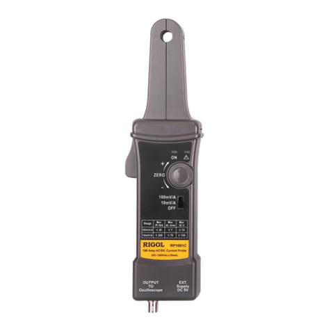
Rigol
Rigol RP1001C User manual
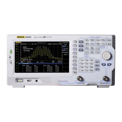
Rigol
Rigol DSA800 Series User manual
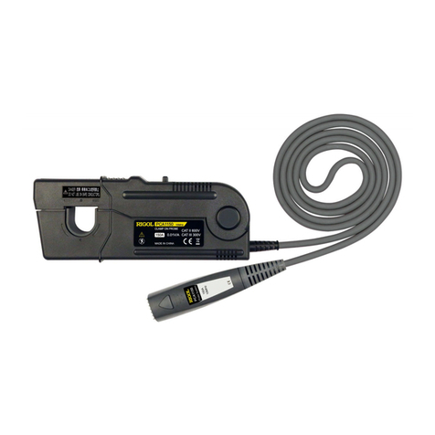
Rigol
Rigol PCA1030 User manual
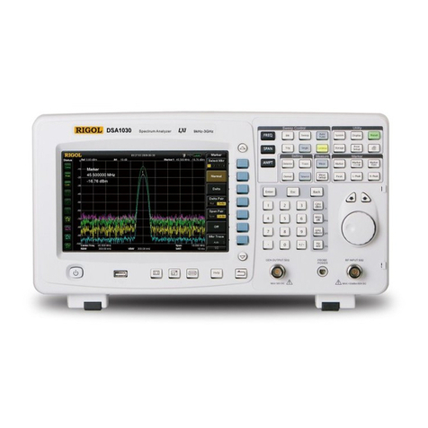
Rigol
Rigol DSA1000 Series User manual

Rigol
Rigol DSA800 Series User manual

Rigol
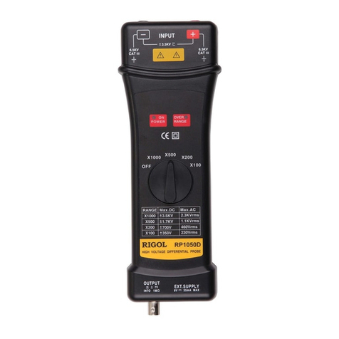
Rigol DSA1000 Series Installation and operation manual
Rigol
Rigol RP1000D Series User manual

Rigol
Rigol DS6000 Series Installation and operating instructions

Rigol
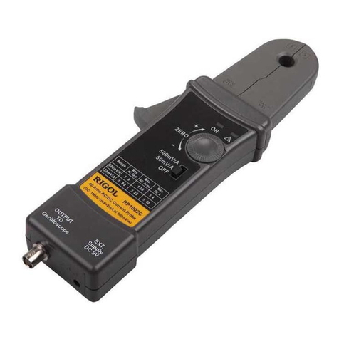
Rigol RP1000D Series User manual
Rigol
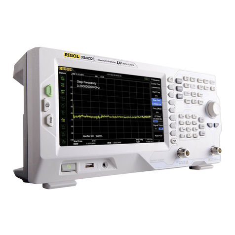
Rigol RP1002C User manual
Rigol
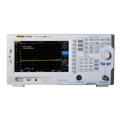
Rigol DSA815 User manual
Rigol
Rigol DSA800E Series User manual
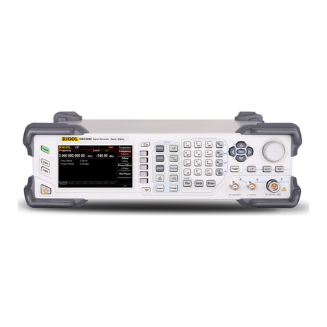
Rigol
Rigol DSG3030-IQ User manual
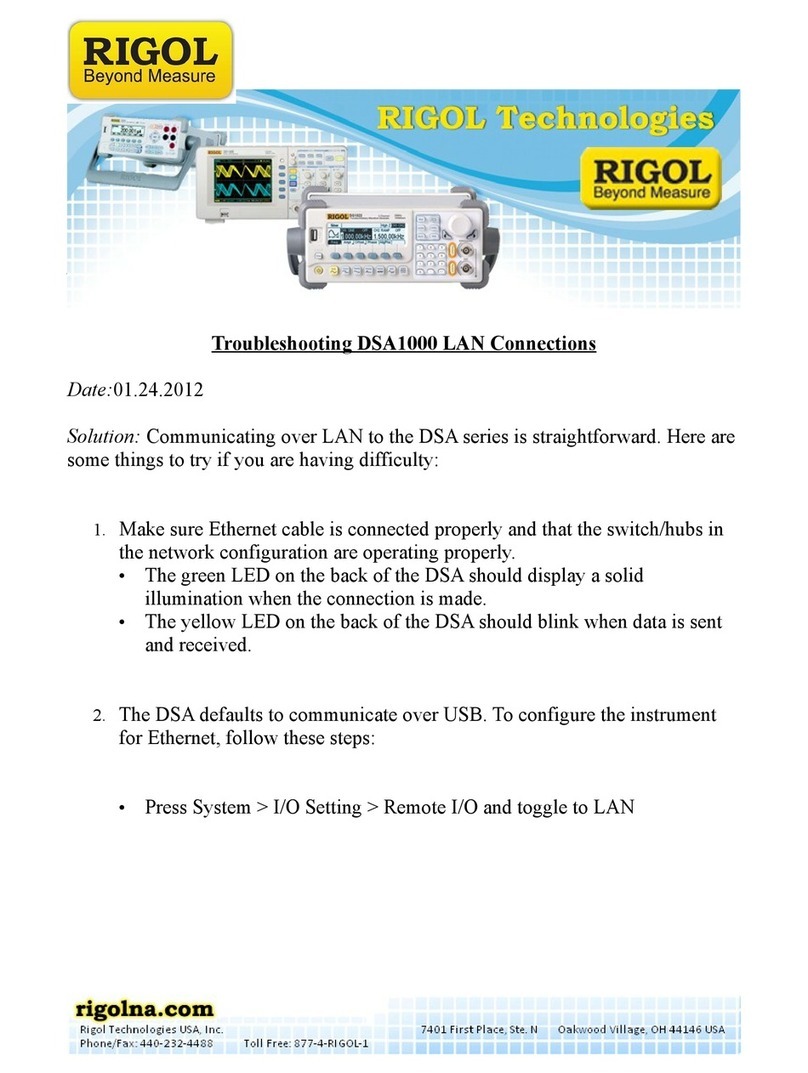
Rigol
Rigol DSA1000 Series Operating instructions
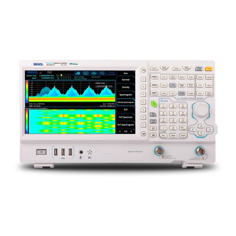
Rigol
Rigol RSA3000E Series User manual
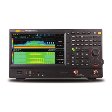
Rigol
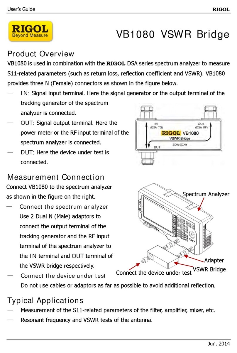
Rigol RSA5065 User manual
Rigol
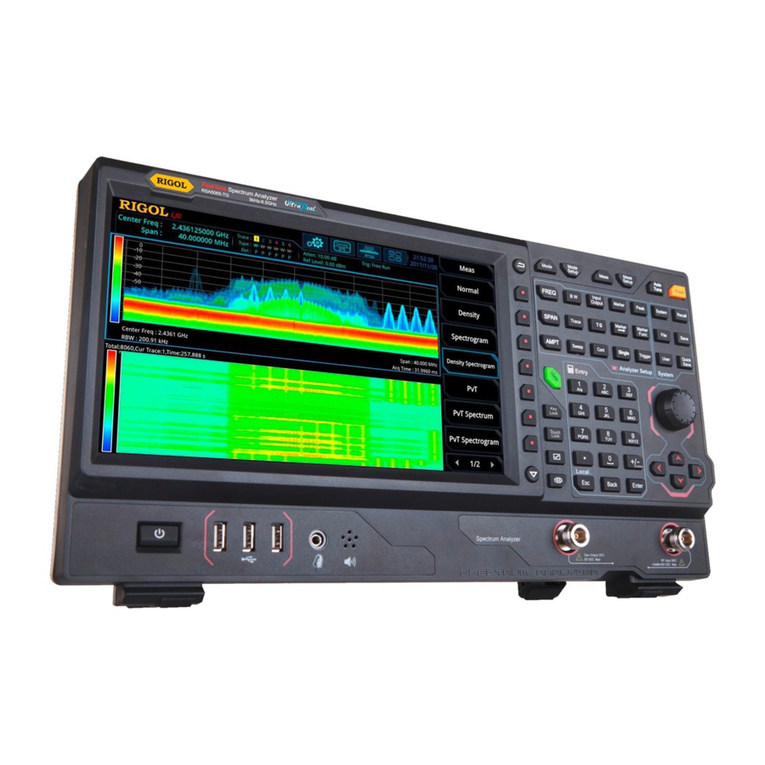
Rigol VB1080 User manual
Rigol
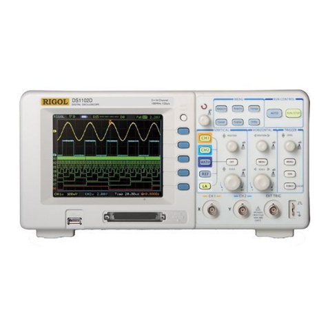
Rigol RSA Series Operating instructions
Rigol
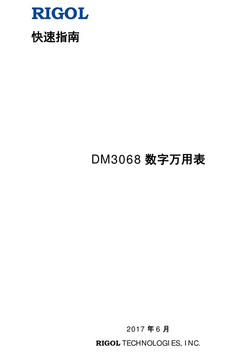
Rigol DS1000E Series, DS1000D Series Operating instructions
Rigol
Rigol DM3068 User manual
Popular Measuring Instrument manuals by other brands

Powerfix Profi
Powerfix Profi 278296 Operation and safety notes

Test Equipment Depot
Test Equipment Depot GVT-427B user manual

Fieldpiece
Fieldpiece ACH Operator's manual

FLYSURFER
FLYSURFER VIRON3 user manual

GMW
GMW TG uni 1 operating manual

Downeaster
Downeaster Wind & Weather Medallion Series instruction manual

Hanna Instruments
Hanna Instruments HI96725C instruction manual

Nokeval
Nokeval KMR260 quick guide

HOKUYO AUTOMATIC
HOKUYO AUTOMATIC UBG-05LN instruction manual

Fluke
Fluke 96000 Series Operator's manual

Test Products International
Test Products International SP565 user manual

General Sleep
General Sleep Zmachine Insight+ DT-200 Service manual
