manuals.online logo
Brands
  1. Home
  2. •
  3. Brands
  4. •
  5. Rigol
  6. •
  7. Measuring Instrument
  8. •
  9. Rigol DSA1000 Series Administrator Guide

Rigol DSA1000 Series Administrator Guide

RIGOL TECHNOLOGIES USA INC
877-4-RIGOL-1 How-To Guide
info@rigol.com
www.rigolna.com
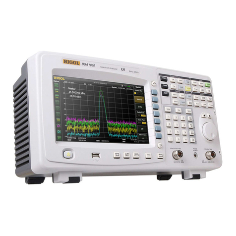
Rigol DSA1000
Application Note
Application Notes
Comparison Guides
FAQs
How-To Guides
Programming Manuals
Quick Start Guides
Support Information
User’s Guides
RIGOL TECHNOLOGIES USA INC
877-4-RIGOL-1 How-To Guide
[email protected]
www.rigolna.com
DSA1000 Tutorial Intro
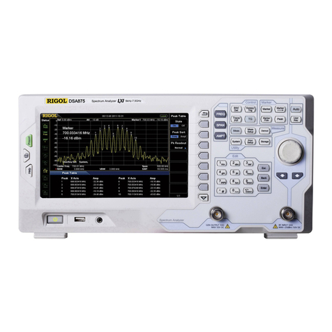
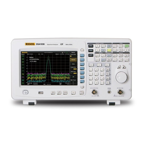
DSA1000 is Rigol’s line of spectrum analyzers. Throughout this
tutorial we will attempt to introduce some of the significant
capabilities of the DSA1000 family in addition to demonstrating the
ease of use of its interface.
Displaying the spectrum of a signal:
For this experiment, the following equipment will be needed:
-Function Generator
-Coaxial cable connector N-Type connector to BNC connector
Set the function generator to output a 100 mVpp sine wave at
100MHz. Then connect the function generator to the RF input of the
DSA1000 series analyzer. After connecting the function generator to
the spectrum analyzer, you should observe a spectrum graph as
observed below.
RIGOL TECHNOLOGIES USA INC
877-4-RIGOL-1 How-To Guide
[email protected]
www.rigolna.com
Now, press the Auto-Tune button (under Sweep Control). You should
know observe the following spectrum graph as below:
The Auto-Tune feature is a very useful and time saving feature to use.
Whenever faced with uncertainty about the position of the center
frequency on the spectrum graph, the Auto-Tune feature will assist
the user center the display at the highest peak in the input signal.
Markers:
Markers are used for the purpose of obtaining accurate
information about a specific data point on the spectrum graph.
For demonstration purposes, with the DSA1000 in the same state as
the figure above, press the “Peak” key.
RIGOL TECHNOLOGIES USA INC
877-4-RIGOL-1 How-To Guide
[email protected]
www.rigolna.com
As observed a marker will be placed at the center of the display. The
peak button is used for the purpose of placing a marker at the
highest point amplitude wise of on the spectrum graph as in the
picture below:
Similarly, if another peak exists to the left or the right of the current peak,
using the “L-Peak” and “R-Peak” buttons allows us to navigate amongst signal
peaks. In the above case, only one real peak exists, as this is a pure sine wave.
Alternatively, the peak menu on the left can be used to navigate through the
signal’s peak. It appears when the “Peak” button is pressed.
RIGOL TECHNOLOGIES USA INC
877-4-RIGOL-1 How-To Guide
[email protected]
www.rigolna.com
Frequency Controls:
Pressing the black “FREQ” button, will expose the Frequency menu on the
right hand side of the screen.
We can see that the frequency is centered at 100 MHz, which is the frequency
of the sine wave being inputted into the system.
Push the “Center Frequency” soft button; this will highlight the center
frequency value selection and using the numeric pad change the center
frequency to a different value. With a new center frequency, we can now
observe a shift in the peak location on the display as below:
RIGOL TECHNOLOGIES USA INC
877-4-RIGOL-1 How-To Guide
[email protected]
www.rigolna.com
Span Adjustment:
In this section we explore the span adjustment capability. First, press the
“Auto tune” button, the peak of the waveform goes back to the center of the
screen.
Press the “SPAN” button, the span side menu will appear on the right hand
side of the screen.
RIGOL TECHNOLOGIES USA INC
877-4-RIGOL-1 How-To Guide
[email protected]
www.rigolna.com
Press the “Span” soft button, using the numeric keypad, enter 10 MHz
RIGOL TECHNOLOGIES USA INC
877-4-RIGOL-1 How-To Guide
[email protected]
www.rigolna.com
Press the “Zero Span” soft button; you will observe the time domain
characteristics of the signal at the center frequency specified, however it’s
worth noting, this option is more useful for observing the envelope of a
modulated wave rather than that of a carrier, though the amplitude of a
carrier wave can be observed:
RIGOL TECHNOLOGIES USA INC
877-4-RIGOL-1 How-To Guide
[email protected]
www.rigolna.com
Press the “Full Span” button; you will observe the characteristics of the entire
visible spectrum to the analyzer, as seen below.
RIGOL TECHNOLOGIES USA INC
877-4-RIGOL-1 How-To Guide
[email protected]
www.rigolna.com
Amplitude Adjustment:
Press the black “AMPT” button; you will observe the amplitude menu on the
right hand side as below:
Press the “Ref Level” soft button; you will observe the amplitude drop down
as below:
Press the “Auto Scale” soft button; you will observe the amplitude return
back to an optimal position on the screen.
Track Generator Usage:
Some DSA units come standard with a Track Generator (TG). A Track
Generator outputs signals at the same frequency as the current sweep
frequency of the RF Input. This can be used for the purpose of characterizing
components and cabling.
RIGOL TECHNOLOGIES USA INC
877-4-RIGOL-1 How-To Guide
[email protected]
www.rigolna.com
Press the “Source” button; the TG side menu will appear on the right
hand side as seen below:
If the TG indicator at the top of the menu is set to off, then press the “TG”
soft button to enable the Track Generator
What we can notice right now is the output of the Track Generator going
through a connecting cable into the RF input of the DSA1000. The graph
above is the characteristic graph of the cable. This is its response to across the
spectrum visible to the DSA1000. In an ideal situation, the cable would have a
flat response across the entire span of the DSA1000. However, due to noise,
interference, imperfections in the cable, we can see slight dips in amplitude at
certain frequencies.
However, in cases where a certain component or device needs to be tested
RIGOL TECHNOLOGIES USA INC
877-4-RIGOL-1 How-To Guide
[email protected]
www.rigolna.com
for its response, it becomes necessary to adjust the TG so that the cables
response is compensated for and we can see a flat response curve.
To accomplish that, we take advantage of the Normalization feature in the TG.
Press the “Normalize” soft button to enter the Normalization menu as seen
below:
RIGOL TECHNOLOGIES USA INC
877-4-RIGOL-1 How-To Guide
[email protected]
www.rigolna.com
To adjust the response, press the “Normalize” soft button. The result is
observed below:
After normalizing the cable, one can now use it to test components or device
response.
RIGOL TECHNOLOGIES USA INC
877-4-RIGOL-1 How-To Guide
[email protected]
www.rigolna.com
For more information or questions contact us directly at:
Rigol Technologies USA
7401 First Place
Suite N
Oakwood Village, OH 44146
You can reach us directly at:
(440) 232-4488
877-4-RIGOL-1
inf[email protected]
www.rigolna.com (Rigol North America website)

Other manuals for DSA1000 Series

3

Other Rigol Measuring Instrument manuals
Rigol RSA Series User manual

Rigol

Rigol RSA Series User manual

Rigol RSA5000 Series User manual

Rigol

Rigol RSA5000 Series User manual

Rigol DSA800 Series User manual

Rigol

Rigol DSA800 Series User manual

Rigol RSA3000 Series Installation and operation manual

Rigol

Rigol RSA3000 Series Installation and operation manual

Rigol RSA5000 Series Installation and operation manual

Rigol

Rigol RSA5000 Series Installation and operation manual

Rigol RSA3030 User manual

Rigol

Rigol RSA3030 User manual

Rigol DS1102Z-E User manual

Rigol

Rigol DS1102Z-E User manual

Rigol M300 Series User manual

Rigol

Rigol M300 Series User manual

Rigol DSA700 series User manual

Rigol

Rigol DSA700 series User manual

Rigol DS6104 Administrator Guide

Rigol

Rigol DS6104 Administrator Guide
Rigol RSA5000-VNA User manual

Rigol

Rigol RSA5000-VNA User manual

Rigol DS1202Z-E User manual

Rigol

Rigol DS1202Z-E User manual

Rigol DSA800 Series User manual

Rigol

Rigol DSA800 Series User manual

Rigol DSA800E Series Operating instructions

Rigol

Rigol DSA800E Series Operating instructions

Rigol RSA3045 User manual

Rigol

Rigol RSA3045 User manual

Rigol PCA1500 User manual

Rigol

Rigol PCA1500 User manual

Rigol DSA800 Series User manual

Rigol

Rigol DSA800 Series User manual

Rigol DSA815 User manual

Rigol

Rigol DSA815 User manual

Rigol MSO8000 Series User manual

Rigol

Rigol MSO8000 Series User manual

Rigol RP1001C User manual

Rigol

Rigol RP1001C User manual
Rigol RSA5065 User manual

Rigol

Rigol RSA5065 User manual

Rigol RP1000D Series User manual

Rigol

Rigol RP1000D Series User manual

Rigol RPL1116 User manual

Rigol

Rigol RPL1116 User manual

Rigol RSA3030-TG User manual

Rigol

Rigol RSA3030-TG User manual
Popular Measuring Instrument manuals by other brands

Extech Instruments 461995 user manual

Extech Instruments

Extech Instruments 461995 user manual

Galvanic Applied Sciences 943-TGX Operation manual

Galvanic Applied Sciences

Galvanic Applied Sciences 943-TGX Operation manual

Pyxis IK-76SSS-S03 user manual

Pyxis

Pyxis IK-76SSS-S03 user manual

R&S RT-ZP05S user manual

R&S

R&S RT-ZP05S user manual

Tegam R1M-A Operation and maintenance manual

Tegam

Tegam R1M-A Operation and maintenance manual

PSI SpectraPen mini Manual and user guide

PSI

PSI SpectraPen mini Manual and user guide

elsner elektronik TH PF Series Technical specifications and installation instructions

elsner elektronik

elsner elektronik TH PF Series Technical specifications and installation instructions

Omega TRCN443 user guide

Omega

Omega TRCN443 user guide

Spectrum 3415F user manual

Spectrum

Spectrum 3415F user manual

Camlogic PFG05L Series Use and maintenance manual

Camlogic

Camlogic PFG05L Series Use and maintenance manual

Compu-Flow C6 quick start guide

Compu-Flow

Compu-Flow C6 quick start guide

Konica Minolta CM-3600D brochure

Konica Minolta

Konica Minolta CM-3600D brochure

Keysight N4376E Getting started guide

Keysight

Keysight N4376E Getting started guide

tams elektronik GBM-1 manual

tams elektronik

tams elektronik GBM-1 manual

Burster RESISTOMAT 2408 manual

Burster

Burster RESISTOMAT 2408 manual

MIB Flowmax 242i operating manual

MIB

MIB Flowmax 242i operating manual

Lutron Electronics YK-37UVSD Operation manual

Lutron Electronics

Lutron Electronics YK-37UVSD Operation manual

TESTO 454 Getting started

TESTO

TESTO 454 Getting started

manuals.online logo
manuals.online logoBrands
  • About & Mission
  • Contact us
  • Privacy Policy
  • Terms and Conditions

Copyright 2025 Manuals.Online. All Rights Reserved.