Riken Keiki RM-5000 Series Use and care manual

T1E-0740
Indicator/Alarm Unit
RM-5000 Series
RS-485(Modbus-RTU)
Manual for Communication Function

- 1 -
<Preface>
Preface
Thank you for purchasing our indicator/alarm unit RM-5000 series.
This manual is a guide to use communication function of RM-5000 series. All persons who use this unit
for the first time and who has ever used this unit are requested to read through this manual to understand
the contents before use.
Communication function of RM-5000 is a part of communication equipment in a network system on a field.
Be sure to read manuals of the equipment related to the network system.
Limitation of Liability
We do not take the responsibility for the result which is caused by the program of the equipment which
communicates with RM-5000.
Numerical notation
Decimal notation : Only numerical value (1, 100, 1000 etc.)
Hexadecimal notation : “0x” is added to the head of the value (0x00, 0x64, 0x3EB etc.)
NOTE
It is prohibited to reprint or reproduce the contents of this manual without our permission unless
otherwise provided for in laws and regulations
The contents of this manual may be changed without notice because of the improvement of the
product.

RM-5000 - 2 -
<Contents>
1.Basic Information................................................................................................................... 3
2.Register Map......................................................................................................................... 4
2-1. RM-5000 Modbus Register Map ....................................................................................... 4
2-2. Operation List of Status Data (Address40001) .................................................................. 6
3.Communication Specification ................................................................................................ 7
3-1. RM-5000 series................................................................................................................. 7
3-2. Modbus Protocol ............................................................................................................... 8
4.Appendix ............................................................................................................................... 9
4-1. Address Setting Method .................................................................................................... 9
4-2. Wire Connection Method................................................................................................... 10
4-3. Setting of the terminating resistance ................................................................................. 13

RM-5000 - 3 -
1
Basic Information
Basic information to use communication function RS-485(Modbus-RTU) of RM-5000
Setting address
You can set Modbus address of RM-5000 to 1-128
The number of the simultaneous connection
Max. 127 sets against 1 x master unit
Transmission Mode
RM-5000 supports RTU mode only although Modbus has ASCII mode (transmitted by ASCII strings)
and RTU mode (transmitted by binary transmission).
Available function
The following Modbus function is available.
0x03:Read Holding Register
Exceptional response
In the following cases, RM-5000 responds exceptional response of Modbus
1) In a case that unavailable function is selected
(Available function on RM-5000 is 0x03)
Example:
Query : 010500000000**** ←Function code = 0x05
Response : 018500000000**** ←Exceptional response: Incorrect function
(0x80’s or is replied to receiving function)
2) In a case that nonexistent data field is selected.
(Data field of RM-5000 is 40001~40032)
Example:
Query : 010300870001**** ←Data field = 40136
Response : 018300870001**** ←Exceptional response: Incorrect data field
(0x80’s or is replied to receiving function)

2-1. RM-5000 Modbus Register Map
4
2
Register Map
2-1. RM-5000 Modbus Register Map
RM-5000 Modbus register map
address Item Content
40001
Status Data
(Refer to the graph in
page 7) *1
Bit 0 to 1 = Magnification (0: actual size, 1: one tenth, 2: one hundredths, 3:one
thousandth)
Bit 2 to 3 = Unit (0: vol%, 1: %LEL, 2: ppm, 3: ppb)
Bit 4 = Setting information for double range
(1: L side, 0: H side and single range )
Bit 5 = Flag for flow trouble
Bit 6 = Not used
Bit 7 = Flag for sensor trouble
Bit 8 = Flag for 1st alarm
Bit 9 = Flag for 2nd alarm
Bit 10 = Flag for smoke alarm (SiO2)
Bit 11 = Flag for full scale over
Bit 12 = Initial flag
Bit 13 = INHIBIT flag
Bit 14 = Flag for alarm test
Bit 15 = Flag for maintenance mode
40002
4-20mA
Input/output Information
SC type (4-20mA input) = 800 to 4000
Except for SC type (4-20mA output) = 800 to 4000
(Notice)
・4-20mA input can be 0mA to 33mA and the data range is 0 to 6600.
・4-20mA output is set at 800 even it is in negative value. Upper limit is normally
F.S.+1digit, and in maintenance it is until 1.2 times of F.S. (F.S. equivalent =
4000)
40003
Gas Concentration Data
*2, *3
Signed integer
Significant figures of gas concentration which is made to integer. Actual Gas
concentration is calculated by multiplying this integer by bit 0 to 1 of address
40001, 40018 or 40028.
40004
to
40011
Reservation
40012 Full Scale Value
Signed integer
Significant figures of full scale value which is made to integer. Actual full scale
is calculated by multiplying this integer by bit 0 to 1 of address 40001 or 40018.
40013 1st Alarm Point
Signed integer
Significant figures of 1st alarm point which is made to integer. Actual 1st alarm
point is calculated by multiplying this integer by bit 0 to1 of address 40001,
40018 or 40028.
40014 2nd Alarm Point
Signed integer
Significant figures of 2nd alarm point which is made to integer. Actual 2nd alarm
point is calculated by multiplying this integer by bit 0 to 1 of address 40001,
40018 or 40028.
40015 Peak Value
Signed integer
Significant figures of peak value which is made to integer. Actual peak value is
calculated by multiplying this integer by bit 0 to 1 of address 40001, 40018 or
40028.
40016
New Flag for
Alarm/trouble
Bit 0 = New flag for 1st alarm
Bit 1 = New flag for 2nd alarm
Bit 2 = New flag for trouble

2-1. RM-5000 Modbus Register Map
5
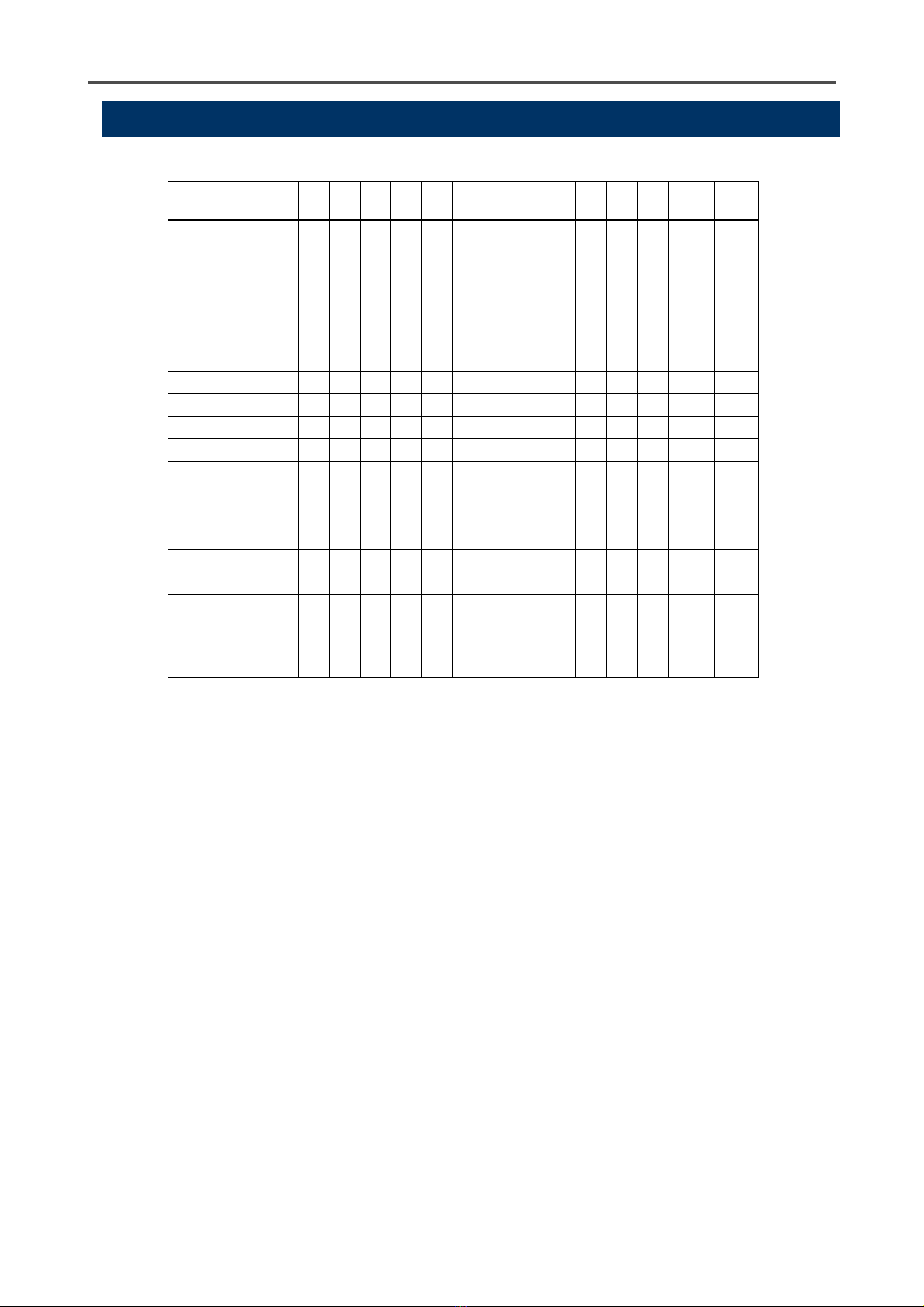
Address Item Content
40017 Digit
Signed integer
Significant figures of digit which is made to integer. Actual
digit is calculated by multiplying this integer by bit 0 to 1 of
address 40001 or 40018.
40018 Decimal Point Position 0: actual size, 1: one tenth, 2: one hundredth, 3: one thousandth
40019 Unit 0: vol%, 1: %LEL, 2: ppm, 3: ppb
40020 X 10 Scale Information
Information of ten times measuring range(H side and single
range)
Address 40012: Full scale value, Address 40013: 1st alarm point,
Address 40014: 2nd alarm point, address 40015: convert peak
value by ten times.
40021
~
40025
Gas Name Gas name = ASCII code 10 letters
40026 Full Scale Value in L side
Signed integer: L side full scale in double range
Significant figures of L side full scale which is made to integer.
Actual L side full scale is calculated by multiplying this integer by
bit 0 to1 of address 40028.
40027 L side Digit
Signed integer: L side digit in double (W) range
Significant figures of L side digit which is made to integer. Actual L
side digit is calculated by multiplying this integer by bit 0 to 1 of
address 40028.
40028
Decimal Point Position in L
side
Position of L side decimal in double (W) range
0: actual size, 1: one tenth, 2: one hundredth, 3: one thousandth
40029 L side Unit L side Unit in double (W) range
0: vol%, 1: %LEL, 2: ppm, 3:ppb
40030
x10 Scale Information in L
side
Information of ten times measuring range (L side in double (W)
range)
Address 40026: full scale value, Address 40013: 1st alarm,
Address 40014: 2nd alarm, Address 40015: convert peak value by
ten times
40031
Concentration Value of H
(High) side in case of double
(W) range
Signed integer: Concentration value of H (High) side in case of
double (W) range
Significant figures of concentration of H side which is made to
integer. Actual concentration of H side is calculated by multiplying
this integer by bit 0 to 1 of address 40001 or 40018.
40032 AMP Types 0: GP, 1: NC, 2: NCW, 3: OX, 4: GH, 5: HART, 6: SC

2-2. Operation List of Status Data (address40001)
6
2-2. Operation List of Status Data (address40001)
●: BitON ○: Bit OFF -: Unsettled
※ In H-HH/L-LL alarm type : ● In L-H alarm type : ○
NOTES:
*1 In maintenance mode, the alarms do not work even if the gas concentration gets over the alarm
point.
*2 In maintenance mode, the gas concentration could be minus. When alarm process is activated by
gas concentration data, make a design with consideration of negative value (complete
representation).
*3 The gas concentration becomes an integer which maintains the number of significant digits.
Examples)
①If the gas concentration is 20.9 in full scale 25.0 →209
②If the gas concentration is 0.2 in full scale 50.0→2
③If the gas concentration is 0.20 in full scale 5.00→20
Status 1
5
1
4
1
3
1
2
11 1
0
9876543,2 1,0
maintenance
Test
Inhibit
Initial
Range over
Smoke(SiO2)
2nd Alarm
1st Alarm
Trouble :
senso
r
Unused
Trouble : flow
Information of
double ran
g
e
Unit Code of
gas
concentration
Decimal Code
Normal :
Measuring
○ ○ ○○○○○○○○○○ - -
Alarm : 1st ○ ○ ○○○○○●○○○○ - -
Alarm : 2 nd ○ ○ ○○○○●※○○○○ - -
Alarm : Smoke ○ ○ ○○●●●●○ ○ ○ ○ - -
F.S. over ○ ○ ○○●○--○○○○ - -
Constant time
after power on
(or after reboot)
○ ○ ○●○○○○○○○○ - -
Maintenance ● ○ ○○-○--○○○○ - -
Alarm Test ● ● ○○-○--○○○○ - -
Trouble : Sensor ○ ○ ○○○○○○●○○○ - -
Trouble : Flow ○ ○ ○○○○○○○○●○ - -
Measuring of L
side
○ ○ ○○○○○○○○○● - -
Inhibit ● ○ ●○○○○○○○○○ - -

3-1. RM-5000 Series
7
3
Communication
Specification
3-1. RM-5000 Series
Contents Specification
Electrical specification Based on EIA RS-485
Communication specification 2 wire Half Duplex
Synchronization method Asynchronous
Connection form 1:N
Maximum connectable number 127 ea against 1 x master unit
Protocol Modbus-RTU
Available Function
03 Read Holdind Register
Transmission speed 4800bps/9600bps/19200bps/38400bps*
Length of data 8bit
Parity nothing/odd/even*
Stop bit 1bit*/2bit
Error check CRC-16
* : Default value
*
NOTICE
Maximum transmission distance is 1.2km

3-2. Modbus Protocol
8
3-2. Modbus Protocol
Modbus communication is based on master/slave method, that can communicate with some slaves. Master
sends a message to slaves, and slaves send back a response.
Message frame of Modbus-RTU mode
Address Function Data Error Check
8bit(0 –128) 8bit N*8bit(Depends on the function) 16bit(CRC-16)
Address
Setting address of slaves
Function
Setting function code you want to carry out
Error check (CRC-16)
CRC -16 is binary of 16 bits, and sending side calculates and adds the calculated value to the message.
Receiving side must confirm that the error check value is same as the calculated value. If it is not same,
the received message becomes error.
CRC-16 Calculation Method
・It performs XOR of the register initialized by FFFF(Hex) and the byte data of the message.
・The result value is shifted 1 bit to the direction of the last figure.(Shift 1 bit to right)
・In case that the last figure is 1, performs XOR of register and A001(Hex).
・This is repeated 8 times(for 8bit)
・The value of this register becomes the CRC level when this calculation is performed for the byte data of the
message.

4-1. Address Setting Method
9
4
Appendix
4-1. Address Setting Method
Explanation of the keys
①MODE key
②ALM2/▲key
③ALM1/▼key
④TEST/SET key
Setting procedure
①Move to a maintenance mode by pressing and holding MODE key.
(Display : [1-1/ZERO] )
②Select display [1-8/M MODE] by pressing ▲▼ key, and press SET key.
(Display : [----/M MODE] )
③Press and hold SET key again.
(Display : [2-0/GAS TEST] )
④Select display [2-6/SETTING2 ] by pressing ▲▼ key, and press SET key
(Display : [SE 0/ADDRESS] )
⑤Press SET key
(Display : [XX/MAC1] )
⑥Set address by pressing ▲▼ key and press SET key.
(Display : [SE 0/ADDRESS] )
⑦Press and hold MODE key to complete the maintenance mode.
MODE
ALM2
▲
ALM1
▼
TEST
SET
④
①
③
②


Other manuals for RM-5000 Series
2
Table of contents
Other Riken Keiki Security System manuals