Riken Keiki RM-6000 Series User manual

PT1E-1099
Indicator/Alarm Unit
RM-6000 Series
Operating Manual

RM-6000 - 1 -
<Contents>
1. Outline of the Product........................................................................................................... 2
1-1. Preface........................................................................................................................... 2
1-2. Purpose of use ............................................................................................................... 2
1-3. Definition of DANGER, WARNING, CAUTION, and NOTE ............................................ 3
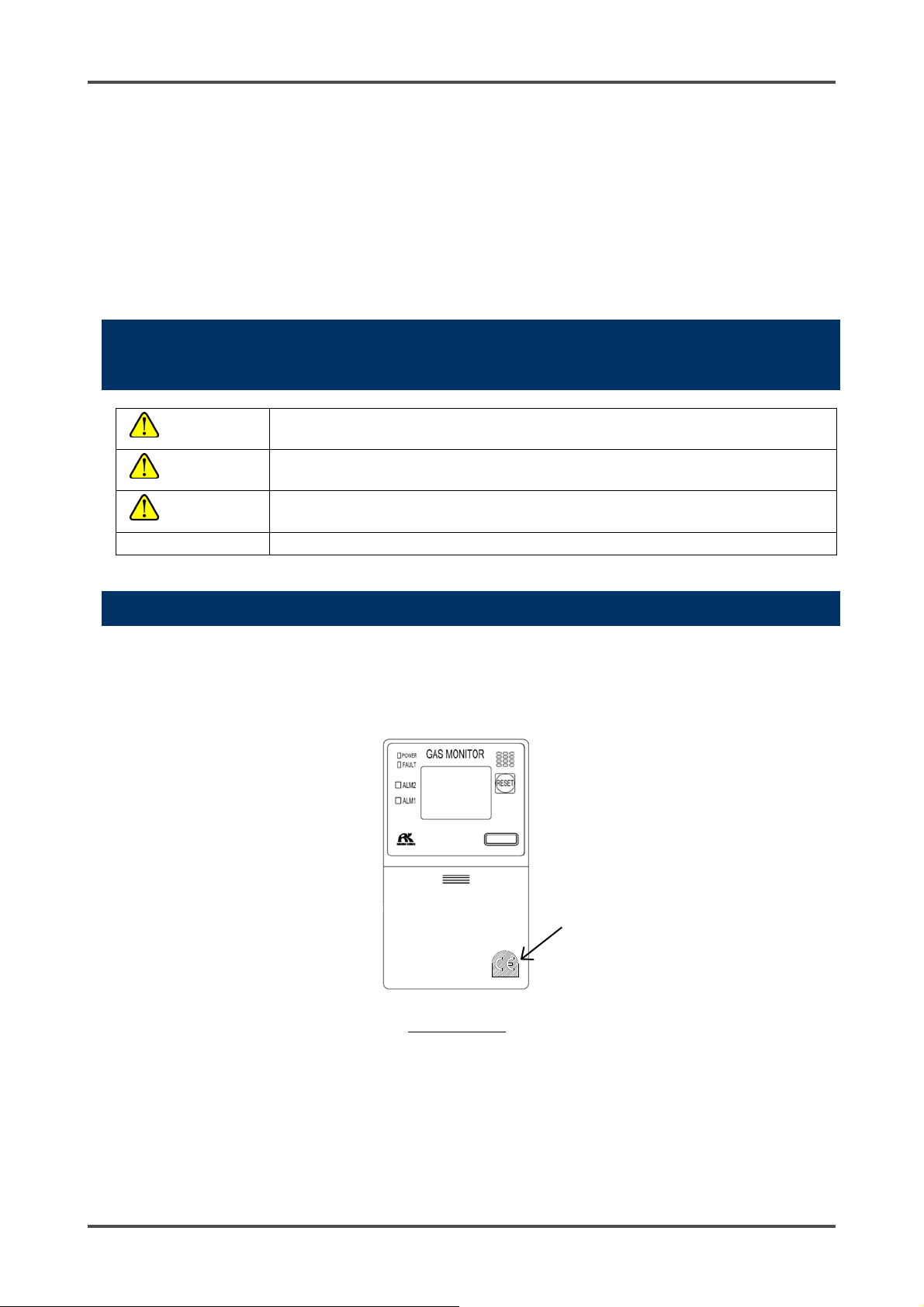
1-4. Method of confirmation for CE marking type .................................................................. 3
2. Important Notices on Safety ................................................................................................. 4
2-1. Danger cases ................................................................................................................. 4
2-2. Warning cases................................................................................................................ 5
2-3. Precautions .................................................................................................................... 6
3. Product Components............................................................................................................ 7
3-1. Main unit and accessories .............................................................................................. 7
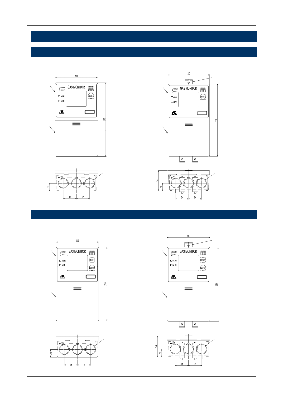
3-2. Outline drawing .............................................................................................................. 8
3-2-1. Self-latching/auto-reset operation specifications ...................................................... 8
3-2-2. Lock-in operation specifications ............................................................................... 8
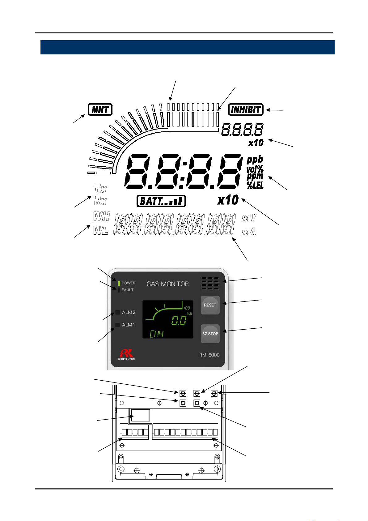
3-3. Names and functions for each part................................................................................. 9
3-4. Block diagram................................................................................................................. 12
4. How to Use........................................................................................................................... 13
4-1. Before using the indicator/alarm unit .............................................................................. 13
4-2. Precautions for installation points................................................................................... 13
4-3. Precautions for system designing................................................................................... 15
4-4. How to install .................................................................................................................. 17
4-5. How to wire..................................................................................................................... 19
5. How to Operate .................................................................................................................... 27
5-1. Preparation for start-up................................................................................................... 27
5-2. Basic operating procedures............................................................................................ 28
5-3. How to start the indicator/alarm unit ............................................................................... 29
5-4. Modes ............................................................................................................................ 30
5-5. Detection mode .............................................................................................................. 32
5-6. Alarm test mode ............................................................................................................. 33
5-7. User mode...................................................................................................................... 34
5-8. How to exit...................................................................................................................... 38
6. Operations and Functions .................................................................................................... 39
6-1. Gas alarm activation....................................................................................................... 39
6-2. Fault alarm activation ..................................................................................................... 42
6-3. External output operation ............................................................................................... 43
6-4. Other functions ............................................................................................................... 45
7. Maintenance......................................................................................................................... 47
7-1. Maintenance intervals and items .................................................................................... 47
7-2. Regular maintenance mode ........................................................................................... 49
7-3. Gas calibration method .................................................................................................. 65
7-4. How to clean................................................................................................................... 68
7-5. How to replace the fuse.................................................................................................. 68
8. Storage, Relocation and Disposal ........................................................................................ 69
8-1. Procedures to store the indicator/alarm unit or leave it for a long time........................... 69
8-2. Procedures to relocate the indicator/alarm unit or use it again....................................... 69
8-3. Disposal of products....................................................................................................... 69
9. Troubleshooting.................................................................................................................... 70
10. Product Specifications ..................................................................................................... 73
10-1. List of specifications ..................................................................................................... 73
10-2. List of accessories........................................................................................................ 75
11. Definition of Terms .............................................................................................................. 76

- 2 -
1
Outline of the Product
1-1. Preface
Thank you for choosing our indicator/alarm unit RM-6000 series for use with the gas detection and alarm
system. Please check that the model number of the product you purchased is included in the specifications
on this manual.
This manual explains how to use the indicator/alarm unit and its specifications. It contains information
required for using the indicator/alarm unit properly. Not only the first-time users but also the users who have
already used the product must read and understand the operating manual to enhance the knowledge and
experience before using the indicator/alarm unit.
1-2. Purpose of use
Use the indicator/alarm unit RM-6000 series in combination with a gas detector head on an one-on-one
basis.
GP-6001: Combustible gas indicator/alarm unit to be used in combination with a catalytic
combustion type detector head
NC-6001: Combustible gas indicator/alarm unit to be used in combination with a new ceramic type
detector head
NC-6001W: Combustible gas indicator/alarm unit with double range specifications to be used in
combination with a new ceramic type detector head
SP-6001: Combustible gas or toxic gas indicator/alarm unit to be used in combination with a hot-wire
semiconductor type detector head
GH-6001: Combustible gas or toxic gas indicator/alarm unit to be used in combination with a
semiconductor type detector head
EC-6002: Toxic gas indicator/alarm unit to be used in combination with an electrochemical type
detector head
OX-6001: Oxygen indicator/alarm unit to be used in combination with a detector head that uses an
oxygen sensor
OX-6002: Oxygen indicator/alarm unit to be used in combination with a detector head that uses an
oxygen sensor
RM-6002: Indicator/alarm unit to be used in combination with a gas detector head that outputs
general measurement signals
RM-6003: Gas indicator/alarm unit to be used in combination with a gas detector head with 3-wire
type 4 - 20 mA output specifications
RM-6003T: Toxic gas indicator/alarm unit to be used in combination with a semiconductor type
detector head (GD-A44V) with 3-wire type 4 - 30 mA output specifications

1 Outline of the Product 1-3. Definition of DANGER, WARNING, CAUTION, and NOTE
- 3 - RM-6000
The gas detection and alarm system is a safety unit, not an analyzer or densitometer which performs
quantitative/qualitative analysis/measurement for gases. You must understand the features of the
indicator/alarm unit before using it, so that you can use it properly.
The indicator/alarm unit displays a gas concentration on the character LCD (digital and bar meter display
<three colors of green, yellow, and red>) according to a signal from the detector head. Gas
concentrations are displayed in different colors according to danger levels, i.e., in green if neither of the
alarm setpoints is exceeded, in orange if the first alarm setpoint is exceeded, and in red if the second
alarm setpoint is exceeded.
The indicator/alarm unit has two-step gas alarm contact and fault alarm contact.
The indicator/alarm unit outputs gas concentration in 4 - 20 mA or digital data (RS-485: option).
1-3. Definition of DANGER, WARNING, CAUTION, and
NOTE
DANGER This message indicates that improper handling may cause serious damage on
life, health or assets.
W
ARNING This message indicates that improper handling may cause serious damage on
health or assets.
CAUTION This message indicates that improper handling may cause minor damage on
health or assets.
NOTE This message indicates advice on handling.
1-4. Method of confirmation for CE marking type
The CE marking is labeled on the detector in case of comply with CE mark. Please confirm the instrument
specification before using. Please refer Declaration of Conformity that is at the end of this manual if you
have CE marking type.
CE mark label
CE mark

2 Important Notices on Safety 2-1. Danger cases
RM-6000 - 4 -
2
Important Notices on
Safety
2-1. Danger cases
DANGER
This is not an explosion-proof unit.

2 Important Notices on Safety 2-2. Warning cases
- 5 - RM-6000
WARNING
Specified devices
Connect the indicator/alarm unit only to the specified devices. If it is connected to any unspecified
device, the indicator/alarm unit or the connected device may be damaged.
Power supply
Before turning on the indicator/alarm unit, always check that the voltage is properly applied. Do not
use an unstable power supply
because it may cause malfunctions.
Need of grounding circuit
Do not cut the grounding circuit or disconnect the wire from the grounding terminal.
Defects in protective functions
Before starting the indicator/alarm unit, check the protective functions for defects. When seeming
defects are found in the protective functions, such as protective grounding, do not start the
indicator/alarm unit.
External connection
Before connecting the indicator/alarm unit to the external device, securely connect it to a protective
grounding circuit.
Operation in a gas
Do not operate the indicator/alarm unit in a place where combustible gases or vapors are present.
Operating the indicator/alarm unit in such an environment will lead to extreme dangers.
Response to gas alarm
Issuance of a gas alarm indicates that there are extreme dangers. Take proper actions based on
your judgment.
2-2. Warning cases

2 Important Notices on Safety 2-3. Precautions
RM-6000 - 6 -
CAUTION
Do not use a transceiver near the indicator/alarm unit.
Radio wave from a transceiver, etc. near the indicator/alarm unit or its cables may disturb indication
reading. If a transceiver or other radio wave transmitting device is used, it must be used in a place
where it disturbs nothing.
To restart the indicator/alarm unit, wait for five seconds or more before doing it.
Restarting the indicator/alarm unit in less than five seconds may cause errors.
Do not use the external output of the indicator/alarm unit to control other units.
This is not a control unit. It is not allowed to use the external output of the indicator/alarm unit to
control other units.
Do not disassemble/modify the indicator/alarm unit, or change the settings if not necessary.
Disassembling/modifying the indicator/alarm unit will invalidate the warranty of the performance.
Changing the settings without understanding the specifications may cause alarm malfunctions.
Please use the indicator/alarm unit properly in accordance with the operating manual.
Never fail to perform a regular maintenance.
Since this is a safety unit, a regular maintenance on it and the detector head must be performed to
ensure safety.
2-3. Precautions

3 Product Components 3-1. Main unit and accessories
- 7 - RM-6000
3
Product Components
3-1. Main unit and accessories
<Main Unit (RM-6000 Series)>
<Standard Accessories>
Operating manual
One copy per system regardless of the number of units to be delivered

3 Product Components 3-2. Outline drawing
RM-6000 - 8 -
3-2. Outline drawing
3-2-1. Self-latching/auto-reset operation specifications
<Wall mounting type> <Rack mounting type>
3-2-2. Lock-in operation specifications
<Wall mounting type> <Rack mounting type>
Panel
Cover
Cable inlet
3 - Φ23
Panel
Cover
Cable inlet
3 - Φ23
Rack mounting
bracket
Cable inlet
3 - Φ23
Panel
Cover
Cable inlet
3 - Φ23
Panel
Cover
Rack mounting
bracket

3 Product Components 3-3. Names and functions for each part
- 9 - RM-6000
3-3. Names and functions for each part
<Front Panel and Character LCD>
(11) Power lamp
(12) First alarm lamp
(13) Second alarm
lamp
(14) Fault lamp
(1) Power switch
(4) Mode key
(5) ▲key
(6) ▼key
(7) Test/set key
(15) Buzzer opening
(9) Reset key
(10) Buzzer stop key
(Only for lock-in type)
(2) Terminal plate for
external connection
(for power supply)
(3) Terminal plate for
external connection
(
for si
g
nals
)
(8) Dimming key
(16) Digital display
(18) Gas name and message display
(20) Gas concentration
unit display
(25) Alarm setpoint display
(23) Digital
communication
display
(21) Maintenance
display
(22) Inhibit display
(24) Double range display
(17) Gas concentration
bar meter display
(19) Full scale value
display

3 Product Components 3-3. Names and functions for each part
RM-6000 - 10 -
Number in
the figure
Item Function
(1) Power switch (POWER) Power switch.
(2) Terminal plate for external
connection
(for power supply)
Used to connect power cables.
(3) Terminal plate for external
connection
(for signals)
Used to connect signal cables.
(4) Mode key (MODE) Used to enter the maintenance mode.
It is also used to cancel or skip in a specific mode.
(5) ▲key Used to switch screen or change a value (UP).
Also used to display the second alarm (ALM2) setpoint.
(6) ▼key Used to switch screen or change a value (DOWN).
Also used to display the first alarm (ALM1) setpoint.
(7) Test/set key (TEST/SET) Used to enter the test mode.
It is used for value confirmation and so on in a specific mode.
(8) Dimming key (DIMMER) Used to dim the power lamp or LCD backlight.
(9) Reset key (RESET) Used to stop buzzer sound during an alarm activation.
(10) Buzzer stop key (BZ.STOP)
(*3)
Used to stop buzzer sound during an alarm activation for
lock-in type.
(11) Power lamp (POWER) Power lamp. It lights in green when the power is on.
(12) First alarm lamp (ALM1) First alarm lamp. It lights in red when the first alarm is
reached.
(13) Second alarm lamp (ALM2) Second alarm lamp. It lights in red when the second alarm is
reached.
(14) Fault lamp (FAULT) Fault lamp. It lights in yellow when an abnormality is detected
in the indicator/alarm unit.
(15) Buzzer opening Buzzer sounds during an alarm activation.
(16) Digital display Displays the gas concentration and so on.
(17) Gas concentration bar
meter display
The detectable range (full scale = FS) is divided into 50 with
bars.
The increase in concentration is displayed in proportion to the
full scale.
(18) Gas name and message
display
Displays gas name in chemical formula, etc. (e.g. CH4 for
methane)
(19) Full scale value display Displays the full scale value of a detected gas.
(20) Gas concentration unit
display
Displays the unit according to the specification. (ppm, ppb,
vol%, %, %LEL)
(21) Maintenance display (MNT) Displayed during the maintenance mode. When this indicator
is displayed, the alarm contact is disabled.
(22) Inhibit display (INHIBIT) Displayed when the inhibition (point skip) is set.
(23) Digital communication
display (*1)
For RS-485 communications, this indicator is displayed (TX,
RX) while transmitting data with the upper unit.
(24) Double range display (*2) Displayed for the double range specifications (WH: High
range, WL: Low range).
(25) Alarm setpoint display The detectable range (full scale = FS) is divided into 50 for
alarm setpoint display.
*1: Displayed only on a model with RS-485 (option) mounted.
*2: Displayed only on NC-6001W.
*3: Displayed only on lock-in type.

3 Product Components 3-3. Names and functions for each part
- 11 - RM-6000
<List of Display Symbols>
Gas concentration digital display (seven-segment)
Numbers
0 1 2 3 4 5 6 7 8 9
Alphabet (upper-case)
A B C D E F G H I J K L M
N O P Q R S T U V W X Y Z
Alphabet (lower-case)
a b c d e f g h i j k l m
n o p q r s t u v w x y z
Symbols
- ^ ~
Gas name and message display (14-segment)
Numbers
0 1 2 3 4 5 6 7 8 9
Alphabet (upper-case)
A B C D E F G H I J K L M
N O P Q R S T U V W X Y Z
Symbols
@ + - / ~

3 Product Components 3-4. Block diagram
RM-6000 - 12 -
3-4. Block diagram
*1: Installed only in GP-6001, NC-6001, NC-6001W, SP-6001, GH-6001, OX-6001.
*2: Only on a model with RS-485 (option) mounted.
*3: Displayed only on lock-in type.
Controller
(CPU)
POWER INPUT:
AC specification 100 - 240 VAC
DC specification 24 VDC
Power supply part
Gas alarm contact (ALM1,
ALM2)
Fault alarm contact (FAULT)
* Standard setting of contact
activation
De-energized
(De-energized at a normal
state)
ON-ALARM
(Closed contact at an
alarm state)
Alarm contact controller
Transmitter
4-20 mA DC transmission
Digital data (RS-485)
transmission (*2)
Amplifier (*1)
Controller
(CPU)
LCD display
Bar meter, gas name display,
concentration display, unit display, etc.
Lamp
(POWER) (ALM1) (ALM2) (FAULT)
Operating unit
(MODE) (ALM2/▲) (ALM1/▼)
(TEST/SET)
(DIMMER) (RESET) (BZ.STOP) (*3)
Detector head (option)

4 How to Use 4-1. Before using the indicator/alarm unit
- 13 - RM-6000
4
How to Use
4-1. Before using the indicator/alarm unit
Not only the first-time users but also the users who have already used the product must follow the operating
precautions.
Ignoring the precautions may damage the indicator/alarm unit, resulting in inaccurate gas detection.
4-2. Precautions for installation points
Do not install the indicator/alarm unit in a place with vibrations or shocks.
The indicator/alarm unit consists of sensitive electronic parts. The indicator/alarm unit must be installed in a
stable place without vibrations or shocks and it cannot drop.
Do not install the indicator/alarm unit in a place exposed to water, oil or chemicals.
When selecting installation points, avoid a place where the indicator/alarm unit is exposed to water, oil or
chemicals.
Do not install the indicator/alarm unit in a place where the temperature drops below -10ºC or rises over
50ºC.
The operating temperature of the indicator/alarm unit is -10 to 50ºC. The indicator/alarm unit must be
installed in a stable place where the operating temperature is maintained and does not change suddenly.
Do not install the indicator/alarm unit in a place exposed to direct sunlight or sudden changes in the
temperature.
When you select installation sites, avoid a place where it is exposed to direct sunlight or radiant heat
(infrared rays emitted from a high-temperature object), and where the temperature changes suddenly.
Condensation may be formed inside the indicator/alarm unit, or the indicator/alarm unit cannot adjust to
sudden changes in the temperature.
Keep the indicator/alarm unit (and its cables) away from noise source devices.
When selecting installation points, avoid a place where high-frequency/high-voltage devices exist.
CAUTION
This is a precision device. Because the indicator/alarm unit may not provide the specified
performance in some places (environments), check the environment in the installation point, and
then take appropriate actions if necessary.
Because the indicator/alarm unit plays an important role for safety and disaster prevention, you
must install as many units of the indicator/alarm unit as needed in appropriate points.

4 How to Use 4-2. Precautions for installation points
RM-6000 - 14 -
Do not install the indicator/alarm unit in a place where maintenance of the indicator/alarm unit cannot be
performed or where handling the indicator/alarm unit involves dangers.
Regular maintenance of the indicator/alarm unit must be performed.
Do not install the indicator/alarm unit in a place where the machinery must be stopped when maintenance is
performed in its inside, where parts of the machinery must be removed to perform maintenance, or where
the indicator/alarm unit cannot be removed because tubes or racks prevent access to it. Do not install the
indicator/alarm unit in a place where maintenance involves dangers, for example, near a high-voltage cable.
Do not install the indicator/alarm unit in machinery which is not properly grounded.
Before installing the indicator/alarm unit in machinery, the machinery must be grounded properly.
Do not install the indicator/alarm unit in a place where other gases exist around it.
The indicator/alarm unit must not be installed in a place where other gases exist around it.

4 How to Use 4-3. Precautions for system designing
- 15 - RM-6000
CAUTION
An unstable power supply and noise may cause malfunctions or false alarms.
The descriptions in this section must be reflected on the designing of a system using the
indicator/alarm unit.
4-3. Precautions for system designing
Using a stable power supply
The external output and alarm contact of the indicator/alarm unit may be activated when the power is turned
on, when momentary blackout occurs, or when the system is being stabilized. In such cases, use a safety
power supply, or take appropriate actions on the receiving side.
The indicator/alarm unit must be provided with the following power supply.
Power supply
voltage
AC specification: 100 - 240 VAC ±10% (terminal voltage of the indicator/alarm
unit)
DC specification: 24 VDC ±10% (terminal voltage of the indicator/alarm unit)
Allowed time of
momentary blackout
AC specification: Up to approx.
100 msec
DC specification: Up to approx. 10
msec
(To recover from the momentary
blackout exceeding the above, restart
the indicator/alarm unit.)
Example of actions
To ensure continuous operation and
activation, install a protective power
supply outside the indicator/alarm unit.
Others
Do not use it with a power supply of
large power load or high-frequency
noise.
Example of actions
Use a line filter to avoid the noise source
if necessary.
Heat radiation designing
When it is installed in the closed instrumentation panel, attach ventilation fans above and below the panel.
Introducing protective measures against lightning
If cables are installed outside the factory/plant, or if internal cables are installed in the same duct as the
cables coming from outside the factory/plant, "lightning" will cause problems. Because lightning acts as a
large emission source while cables act as a receiving antenna, devices connected to the cables may be
damaged.
Lightning cannot be prevented. Cables installed in a metal conduit or under the ground cannot be
completely protected from inductive lightning surge caused by lightning. Although complete elimination of
disasters caused by lightning is impossible, the following protective measures can be taken.
Protection against
lightning
Take appropriate measures in accordance with the importance of the facilities
and the environment.
Connect the transmission signal route by using optical fiber.
Provide protection by a lightning arrester (cable arrester).
(Although inductive lightning surge can be transmitted through the cable, it is
prevented by installing a lightning arrester before the field devices and central
processing equipment. For information on how to use a lightning arrester,
please contact the manufacturer.)
Grounding In addition to lightning, there are more sources of surge noise. To protect units
from these noise sources, the units must be grounded.
* The lightning arrester has a circuit to remove a surge voltage which damages field devices,
so that signals may be attenuated by installing the arrester. Before installing a lightning arrester, verify
that it works properly.

4 How to Use 4-3. Precautions for system designing
RM-6000 - 16 -
Proper use of alarm contact
The alarm contact of the indicator/alarm unit is used to transmit signals to activate an external buzzer or
alarm lamp. Do not use the indicator/alarm unit for controlling purpose (e.g., controlling the shutdown valve).
The specifications for the alarm contact of the indicator/alarm unit are based on the resistance load
conditions. If inductive load is used at the alarm contact, the following errors will occur easily because
counter electromotive force is generated at the contact.
Deposition, defective insulation or defective contact at the relay contact
Damage of any electric parts due to high-voltage generated inside the indicator/alarm unit
Abnormal operations by an out-of-control CPU
If load is to be activated, appropriate measures must be taken to stabilize the operation of the
indicator/alarm unit and protect the alarm contact referring to the following information.
Relay it with an external relay at a lower voltage of 100 VAC or below (contact amplification). At the same
time, the surge absorbing part SK1 suitable for the specifications must be attached to the external relay.
In addition, the surge absorbing part SK2 must be attached to the loaded side of the external relay if
necessary.
It may be recommended that the surge absorbing part should be attached to the contact for certain load
conditions. It must be attached to an appropriate position by checking how the load is activated.
CAUTION
The "b" contact (break contact) under de-energized state may be opened momentarily by a physical
shock, such as external force.
When the "b" contact is selected for the alarm contact, take appropriate actions to prepare for a
momentary activation, for example, add signal delay operation (approximately one second) to the
receiving side of the "b" contact.
CAUTION
In principle, do not activate inductive load at the alarm contact of the indicator/alarm unit. (In
particular, never use the inductive load to activate a fluorescent lamp or motor.)
If inductive load is activated, relay it with an external relay (contact amplification). However,
because the coil of an external relay also involves inductive load, select a relay at a lower
voltage (100 VAC or below), and then protect the contact of the indicator/alarm unit with an
appropriate surge absorbing part, such as a CR circuit.
Power
supply
Power
supply
Coil Load
* SK1, SK2: Surge absorbing parts
External relay
(low voltage relay)
A
larm contact

4 How to Use 4-4. How to install
- 17 - RM-6000
4-4. How to install
<Wall mounting type>
NOTE
The wall mounting type is to be installed with switch box on the market. (See below for an attachment example.)
*1 Used for attaching to a switch box.
*2 For fixing RM-6000 and mounting plate
Attach the unit to
the angle.
Pull out the
cables.
Fixing angle
Switch box
Conduit
Case Fixing angle
Mounting hole*1
Mounting hole
*1
Connect the cables.
Mounting plate
(SPCC)
4φ4.5
Mounting hole*2
Press red circle point
and slide down the
cover.
<How to open the cover>
<Installation method>
To install the RM-6000, please follow the steps below.
(1) Please open the cover.
(2) Please remove the mounting plate : Loosen the screws (2 places)
which is fixed RM-6000 and mounting plate.
(3) Please fix mounting plate on the wall by screws (2 places).
(4) Please fix RM-6000 on the mounting plate by screws, and then
please put the cover on the RM-6000.

4 How to Use 4-4. How to install
RM-6000 - 18 -
<Rack mounting type>
<Attaching procedure>
After drilling holes in the panel, attach the indicator/alarm unit according to the following procedure.
(1) Insert RM-6000 to the panel front side.
(2) Set fixing bracket on the upper and lower parts of RM-6000.
(3) Tighten the screws of the fixing bracket.
CAUTION
Tighten the screws with an appropriate tightening torque. Tightening the screws to a high torque
may deform the case or damage the fixing bracket.
Turn off the power of the indicator/alarm unit before attaching or detaching it. Otherwise, a failure
may be caused.
*: n indicates the number of indicator/alarm units

4 How to Use 4-5. How to wire
- 19 - RM-6000
4-5. How to wire
<Recommended Cables>
Model Cable specifications
GP-6001
NC-6001
NC-6001W
SP-6001
Power supply: Equivalent to CVV (1.25 sq or 2.0 sq) 2-core
Detector head: Equivalent to CVV (1.25 sq or 2.0 sq) 4-core or 6-core
Signal: Equivalent to CVVS (1.25 sq or 2.0 sq) 2-core
Contact: Equivalent to CVV (1.25 sq or 2.0 sq) max. 6-core
OX-6001
OX-6002
RM-6002
Power supply: Equivalent to CVV (1.25 sq or 2.0 sq) 2-core
Detector head: Equivalent to CVVS (1.25 sq or 2.0 sq) 2-core
Signal: Equivalent to CVVS (1.25 sq or 2.0 sq) 2-core
Contact: Equivalent to CVV (1.25 sq or 2.0 sq) max. 6-core
GH-6001 Power supply: Equivalent to CVV (1.25 sq or 2.0 sq) 2-core
Detector head: Equivalent to CVVS (1.25 sq or 2.0 sq) 3-core or 5-core
Signal: Equivalent to CVVS (1.25 sq or 2.0 sq) 2-core
Contact: Equivalent to CVV (1.25 sq or 2.0 sq) max. 6-core
EC-6002 Power supply: Equivalent to CVV (1.25 sq or 2.0 sq) 2-core
Detector head: Equivalent to CVVS (1.25 sq or 2.0 sq) 2-core or 4-core
Signal: Equivalent to CVVS (1.25 sq or 2.0 sq) 2-core
Contact: Equivalent to CVV (1.25 sq or 2.0 sq) max. 6-core
RM-6003
RM-6003T
Power supply: Equivalent to CVV (1.25 sq or 2.0 sq) 2-core
Detector head: Equivalent to CVVS (1.25 sq or 2.0 sq) 3-core
Signal: Equivalent to CVVS (1.25 sq or 2.0 sq) 2-core
Contact: Equivalent to CVV (1.25 sq or 2.0 sq) max. 6-core
CAUTION
Use the specified cables for each of the connections between the indicator/alarm unit and the
detector head.
When wiring, be careful not to apply stresses on the terminal plate when (overweight) cables are
installed.
The power cables and signal cables must not be installed together with the motor power cables,
etc.
When stranded wires are used, prevent wires from contacting each other.
Use the specified tools to wire.
This manual suits for next models
11
Table of contents
Other Riken Keiki Security System manuals