Rimage Amigo II Installation instructions

Producer Family™ Operator
112161_B © 2007, Rimage Corporation 1
Align the lift arm to the carousel
Use this procedure to align the lift arm to the carousel in an Autostar II™, Protégé II™, Amigo II™, AutoPrinter II™, Producer
7100™, Producer 8100™, Producer 7100N™, or Producer 8100N™.
Note: Use this procedure if the discs are rubbing on the carousel or are not being picked properly.
The procedures in this document should be performed only by personnel trained and authorized by Rimage. The instructions and
content are written for mechanical and electrical service work assuming the technician has such training and authorization. The
product warranty may become void if equipment or parts are tampered with, misused, neglected, or modified in any respect without
the written consent of Rimage or by technicians who are not authorized or certified by Rimage.
The term “Producer II” is used throughout this document to refer to the Autostar II™, Protégé II™, Amigo II™, AutoPrinter II™,
Producer 7100™, Producer 8100™, Producer 7100N™, and Producer 8100N™.
Before you begin #Required tools
1. Stop or pause all jobs.
2. Power off the Producer II.
3. Disconnect the power cord.
•Disc with an index mark
•Torx T10 screwdriver
•Torx T15 screwdriver
Align the lift arm
1. Place one or more discs with an index mark in any bin.
Note: The lift arm starts to pick discs from bin 1. If a disc is not in bin 1, the lift arm proceeds to the next bin.
Tip: If you do not have a disc with an index
mark, use a black permanent marker and
draw a line on a disc near the center as
shown. The mark should be at least 1 mm
wide and 4 mm long.
1 mm
4 mm
2. Access diagnostic test 5. More information on diagnostic tests is available at www.rimage.com/support.html.
The operator panel displays, CYCLE LIFT cycle = 00000. The lift arm moves down to the carousel and picks up
the disc with an index mark on it. The printer tray opens. The disc rotates until the index mark is located. The lift
arm releases the disc on top of the printer tray. The lift arm picks up the disc and drops it into a bin in the
carousel.
Note: The test continues to cycle media until the operator button is
pressed. When the operator button is
in diagnostic mode.
3.
Note: Stop the test at a different bin each time.
pressed, the system exits the test but remains
Stop the test at bin 2 (press the operator button).

Align the lift arm to the carousel
2 © 2007, Rimage Corporation 112161_B
4. Place a disc on the gripper board assembly by
pushing the disc into the gripper while pressing the
disc release button. Release the disc release
button, the gripper holds the disc.
5. Manually, slowly lower the lift arm and disc to the bin.
-Important! Do not move the carousel.
6. Observe the position of the disc at the four points
shown, but do not adjust the lift arm at this point.
7. Repeat steps 2 – 6 for each bin.
Gripper
Disc
Release
Button

Producer Family
8. If the disc is not aligned to the bins, adjust the lift
arm.
•To adjust the lift arm right or left:
a. Remove the disc from the gripper.
b. Loosen the Torx T15 screw located on the
bottom of the gripper board assembly.
c. Grip the disc release button and slide the
gripper board assembly left or right as
necessary.
Tip: Use the screw and the gap as a
guide to how far you are moving the
gripper board assembly. See below.
d. Tighten the Torx T15 screw.
e. Repeat alignment check.
Left to Right Adjustment
Screw and Gap Disc Release Button
•To adjust the lift arm front to back:
a. Leave the disc in the gripper and loosen
the Torx T10 screw.
-Important! Keep the screwdriver in
position.
b. Gently move the lift arm forward or
backward.
c. While holding the lift arm in position, tighten
the Torx T10 screw.
d. Repeat alignment check.
Front to Back Adjustment
Torx T10
Screw
112161_B © 2007, Rimage Corporation 3

Align the lift arm to the carousel
4 © 2007, Rimage Corporation 112161_B
9. Repeat step 8 until the lift arm is aligned.
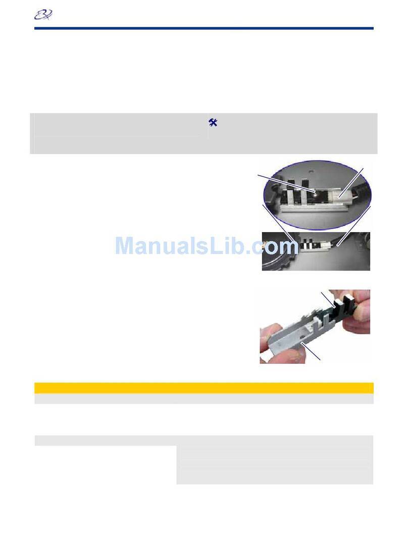
-Important! Ensure that the flag is still centered in the sensor.
Lift Arm
Flag
Lift Arm
Producer II and AutoPrinter II
Side of Unit
Flag
Producer III and Producer IIIN
10. Repeat steps 2 – 7 to ensure that the lift arm is aligned to each bin.
11. Select diagnostic test 19 to exit diagnostic mode. The Producer III is ready for use.

Producer Family
Learn more
Rimage Corporation reserves the right to make improvements to the equipment and software described in this document at any time
without any prior notice. Rimage Corporation reserves the right to revise this publication and to make changes from time to time in
the content hereof without obligation of Rimage Corporation to notify any person or organization of such revisions or changes.
Support information
US, Asia/Pacific, Mexico/Latin America Europe
Rimage Corporation
7725 Washington Avenue South
Minneapolis, MN 55439
USA
Attn: Rimage Services
Service:
North America: 800-553-8312
Asia/Pacific, Mexico/ Latin America: 952-946-0004
Fax: 952-946-6956
www.rimage.com/support.html
When you contact Rimage Services, please provide:
•Unit serial number and software version.
•Functional and technical description of the problem.
Rimage Europe GmbH
Albert-Einstein-Str. 26
63128 Dietzenbach Germany
Tel: +49-(0) 6074-8521-0
Fax: +49-(0) 6074-8521-21
Rimage Europe Technical Website
http://www.rimage.de/support.html
Select the appropriate Support link to learn more. If you
cannot find a solution on our website, email Rimage
•Exact error message received.
Safety Information
Products
This information and the indications on the product allow proper and safe operation. The indication marks below help protect you
and other persons from injury, and equipment from damage.
-Important! Any equipment that has certain components using AC line voltage, or in some cases low DC voltages, such as
power switches, power supplies, fuses, fans, non-stepper motors, must be replaced with Rimage–approved components to
maintain the safety approval issued by UL.
nwarning is used to indicate situations that
nn: Indicates that failure to observe this guideline could result in loss or damage to the equipment, product, software, or
, please read these precautions and familiarize yourself with their meaning before using the equipment.
n
r beam used by the DVD-R recorder is a Class 2 laser and can be harmful to the eyes. Do not attempt to open the
. An authorized technician should perform all service procedures.
nCa
tors,
eplaced with Rimage-approved components to maintain the safety approval issued by UL.
rmation or to order a new power cord, contact Rimage Customer
Service.
This product is designed for an office environment.
Warning! According to ANSI (American National Standards Institute) standards, a
could result in bodily injury to personnel operating or maintaining the equipment.
Cautio
data.
Safety precautions
To ensure safety
Warning!
Use of controls or adjustments or performance of procedures other than those specified herein may result in hazardous
radiant exposure.
The lase
recorder
ution:
All equipment with AC line voltage, or low DC voltages, such as switches, power supplies, fuses, fans, non-stepper mo
must be r
Use only the supplied AC power cord. For more info
112161_B © 2007, Rimage Corporation 5
Other manuals for Amigo II
12
This manual suits for next models
8
Table of contents
Other Rimage Printer Accessories manuals
Popular Printer Accessories manuals by other brands

Franklin Fueling Systems
Franklin Fueling Systems EVO TS-550 installation guide

Roland
Roland PNS-642 Assembly instructions

Xerox
Xerox 5500DN - Phaser B/W Laser Printer instruction sheet

HP
HP 2500 - Color LaserJet Laser Printer installation guide

Epson
Epson TX800-12H user manual

TonerRefillKits
TonerRefillKits ReChargX RX180 instructions