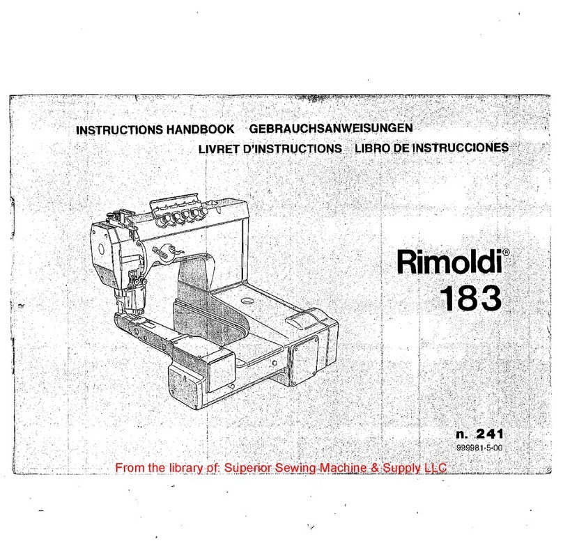
Rimoldi 183 manual

-
:/
-·
--
-
·<
-?~~:f::-11~r;;~r:j'.:~~~t:::'.~;?~;;i:·;1f:~:'.T'.7~~~:~~:::::r::,;:·~::'.:·:tc:'.}t'_:~:?'·,:1:';:',::0j,'':1r0'.~:~:\n~~;
•·
..
·
··1N$TRl!CTIONS.
HANPB.ori~
..
·••·~il3RAllCHSA~~l;ISIJN~Eijc>J'f·c
;
..
,
r
l~9Q@~1~,d~¥t:tJ~~,
.·.:,·.•,··:~:·::::-·:.-
}j/);:'.'":
:•
.
.:1:.~L:·_;:_'.;·/}:-;,:1-.'·/}:•·
:t:122:ili'.~'~:2'.'.JiJj~,&::±t0:J-;;iliL::::w

First
of
all we wish to
thank
you
for showing.
preference for our product.
We
are sure that your
confidence
in
our brand will
be
fully repaid
by
the
long and useful service
that
you
will certainly obtain
.from
the
machine.
This booklet contains some notes
on
the
installation,
operation and maintenance of Rimondi
"Feed
-
off-
the
-arm machines
183"
which should be useful to
owners and should help th~m
to
become familiar
with
the
machine and to derive
the
best results from
it. This machine designed and realized with
the
most
advanced· technologies, was carefully· checked· and
thoroughly tested before leaving
the
factory
to
guarantee
its
-long
life and efficiency; howerer,
it
must
be
remembered
that
these depend very much
on
how
the
machine
is
operated and maintained,
and
it
is therefore in
the
owner's interest
to
read this
book
carefully and follow
the
instructions
in
it,
·before using
the
machine.
Wir
mochten
Ihnen
zu allerst dafilr dank.en, dass
Sie
unsere Maschine bevorzugt haben,
und
wir
-sind
sicher, dass Sie fiir das Vertrauen
in
unserer Fahrik-
mark;e
weitgehend von einem langen,
und
guten
Betrieb, den Sie mit der Maschine haben werden,
weitgehend vergolten sein werden.
Dieses Heft enthiilt einige Hinweise zur Installation,
Einstellung
und
Wartung der Maschinen "ARMAB-
WAR
TS
-Serie 183", die unserer
Meinw1g
nach
fiir Sie niitzlich
~ei.11
wer~en,
um
unsere Maschine
besser zu kennen
und
zweckmiissiger zu verwenden.
Diese Maschine· wurde nach den modernsten
Te-
chnologien studiert
und
realisiert
und
gelangt erst
nach strengen Kontrollen
und
griindlichen Priifungen
zu Ihnen, sodass wir lang~ Lebensdauer
und
hohe
Leistungsfahigkeit garantieren konnen, jedoch
eri11-
i1ern
wir Sie daran, dass diese
in
hohem Masse von
der Beniitzung
und
von einer sorgfiiltigen Wartung
abhangen, die Sie Ihrer Maschine leisten werden.
Wir
raten Ihnen daher
in
Ihrem eigenen Interesse dieses
Heft vor dem Einsatz der Maschine aufmerksam
durchzulesen
um
die darin enthaltenen Anleitungen
genau·
zu
befolgen.
From the library of Superior Sewing Machine & Supply LLC - www.supsew.com

............
"':'
...
_....,.....,....,.
......
...,
...
,
Nous desirons avant-
tout
vous remercier pom: la
confiance accordee anotre produit
et
nous sommes
certains
qu'en
compensation cette machine vous
servira pendant longtenips
et
d'une fa~on tres
profitable.
Ce
livret contient plusieurs notes relatives
a!'installation, la mise au point
et
I'entretien des
machines serie "Base cylindrique deportee
183"
qui
pourront vous etre utiles
pour
m:ieux
connaitrr
et
utili&er
notre produit. Cette machine, etudiee et
com;ue suivant les technologies les plus modernes,
vous arrive apres avoir subi des controles scrupuleux
et des essais rigoureux qui nous
permettent
d'en
garantir la
_duree
et
l'efficience. Cependant, nous
vous rappelons que ces performances dependent
enormement du mode d'emploi
et
de l'entretien qui
seront reserves ala machinf'. Par consequent, avant
de
la faire fonctionner, nous conseillons dans votre
intt':ret,
de
consulter attentivement
ce
livret
et
de
suivre soigneusement les instmctions qu'il contient.
2
m
TKUUUl.:C10N
Deseamos
muy
especialmente agradecerLes
por
la
preferencia otorgada a nuestro producto, segu-
ros que la confianza de la cual hicieron objeto
nuestra marca, sera generosamente retribuida
por
el prolongado y util servicio que sin lugar
a dudas sera brindado
par
la
maquina.
En este libreto
han
sido reunidas algunas notas
correspondientes a la instalacion, questa en fase y
manutenci6n de las maquinas serie "Base cilindrica
reves
183",
que consideramos puedan serLes
de utilidad para conocer mejor y en consecuencia
usar mas provechosamente nuestro producto.
Esta maquina, estudiada y concebida con la tecno-
logia mas moderna, llega hasta Ustedes despues
de
·
controles escnipulosos y severas pruevas que nos
permiten garantizar su duraci6n y eficiencia. Es
indispensable. empero hacerles riotar qu~ esto
ultimo depende en
huena
parte del uso y manu-
tenci6n de la maquina. Aconsejamos
en
conse-
cuencia.antes
de
su empleo, leer con suma atenci6n
este libreto, siguiendo las instrucciones
en
el
contenidas.
From the library of Superior Sewing Machine & Supply LLC - www.supsew.com

N.B.
The
maclune
IS
aespau;rn::u
UUlll
UIAl
uu
...
Lv•;
fitted
with
all safety guards required
by
law.
The current
must
be cut
off
from
the
machine
. motor.
by
operating
the
relative switch,
when
the
needle is changed,
or
presser
foot,
needle
plate
and
looper removed, during breaks
when
the
machin~
is
without
operator, and while maintenance is
be111g
carried out.
The devices
on
the
machine
for
safeguarding
the
operator such as needle guard, needle bar guard,
belt
cover, etc.
must
J1ever
be
removed, except
for
maintenance.
ATTENTION
La
machin-e est livree equipee de toute8
lt>s
pro-
tections prevues
par
les loi8
en
vigµeur
rdatives
a
la
prevention des accidents
du
travail.
Pour
r<>mplacPr,
aiguilles, pied-de-bice, plaque a
aiguilk, crochet,
penda~t
les pausf's
de
travail et
pendant
l'entretien,
il
faut.Mbrancher le
moteur
de
la machine en
mettant
son
interrupteur sur la
position
"arret".
Les dispositifs de securite tels
proteg~~tigiJjlle,
protection
de la ham"
0 ·
aiguille,
carter de protection de
la
courroie,
etc
..
1w
doiVf•nt
en
aucun cas etre ·enleves, exc<"ption faitf'
pour
lPs
operations d'entretien.
Die
in
diesem Heft aufgefiihrte Maschine wird mit.
allen Schutzeinrichtungen, die vom z. Zt. beste-
henden
Arbeitsschutzgesetze vorgesehen
worden
sind. ·
Beim Austausch
der
Nadeln, des Fiisschens, der
Stichplatte, des Greifers, wiihrend der
unhewachteten
Arbeitsunterbrechungen
und
wiihrend der Wartung
muss der Motor mittels des Schalters vom Versor-
gungsnetz ausgeschaltet werden. ,
Siimtliche Schutzeinrichtungen
fur·
die Naherin wie
Nadel, -Nadelstangen -
und
Riemenschutz auf der
Maschine
und
auf dero Motor usw, diirfen
nicht
entfernt
werden. Die einzige Ausn_ahme bildet die
Wartung.
JMPORTANTE
La maquina sale de
nuestra
f
abrica
con
todos
. los elementos de protecci6n impuestos
par
las
leyes de anti-infortunio actualmente
en
vigencia.
Al camhiar la aguja,
quitar
el prensatelas, placa
aguja, crochet, durante las pausas sin
control
del
trabajo y
al
realizat las operaciones de
manuten-
···
ci6n, debera quitarse
la
corriente del
motor
de
la
maquina, apagando
para
ello· el
interruptor
co-
rrespondiente.
3
From the library of Superior Sewing Machine & Supply LLC - www.supsew.com

INTRODUCTION
.............•..•.•..••..
1-3
PRESENTATION . . . . . . . . . . . • • . . . . . . . . . . • . 6
ELECTRICAL
CONNECTIONS..............
. • 8
1 - ~onnection diagrams • . . . • . . . • . . • • . • . . . .
12
INSTALLATION
......................
··
•.
18
Fitting the plate on column stand
...
·.
• . . • . • • . . . . 20
Fittingthe,plate on adjustable stand . . . . . . • . . . . . . 20
Fitting the
motor
. . . . . . . . . . . • • . . • . . . . . • . . • 22
Fitting the shock
absorbers
. . . • . . . . . . . • • . . . . . . 22
Fittingthe machine
head
. . . . . • . . . . . . . • . . . . . . 24
Connection machine head-motor . . . . . . • . . . . • . • •
24
Connection
of
presser
foot
lifter
.•.
,
..
, , , , • , . • • . 26
REFILLING
WITH
OIL
....•.....•...•......
28
REPLACING
AND
ADJUSTING SEWING
MECHANISMS. . . . . . . . . . . . . • • . . • . . . . . . . . . 30
1 -Timing between upper
and
lower shaft . . . . . . . 30
2 -
Needles
...............
·.
. . . . . • . • . . . . 32
3 -
Presser
foot
. . . . • . . • • . . . . • . . . . . . . . • . . 34
4 - Needle plate . . . • . . . . . . . . . . • . . . . . . . . . .
40
5 - Cutters : . . . . . . . . . . . . . . . . . • . . . . . . . • • 42
6 - Lower looper
...•.......••..•....••.•
44
7 -
Feed
dogs
• . . . . . . . . . . . . . . . . . . . • . . . . . 46
8 - Spreader loopers . . . . . . . . . . . . • • . . . . . . • . 52
9 - Movable
front
and
rear
needle
guards
.•..
, . . • 56
ADJUSTING THE
DIFFERENTIAL
FEED
........
62
ADJUSTING THE STITCH LENGTH
............
64
THREADING'AND
ADJUSTING THREAD
TENSIONS . • . . • . . . • . . . . • . . . . . . . . . . • . • . . 66
Adjusting the
needle
thread tension . . . . . • . . • . . •
..
66
Adjusting
and
control
needle
thread take
up.
. . . . . • . 68
Adjusting the additional tension. . • . . . • . . . . . . . . • 70
Threading
and
adjusting the lower looper thread . . . . . 72
Threading
and
adjusting the spreader looper threads. • .
74
MAINTENANCE
•........•...••...•...••..
76
FAUL
TS
DUE
TO UNP
ROPER
USE
OF
MAQHI
NE
. • 79
A
n•,
,r,~
Ill
V V
._n,c1
....
nl'\II~
EINLEITUNG
; . ,
..•...........•......•..
1-3
EINFUEHRUNG
.•.•..•.•••••.•.••••.
, . . . 6
ELEKTRISCHE ANSCHLUESSE
••...•.•..•..
, 8
1-
Anschluss-Schemas
•.....•.....•....
:.
12
INSTALLATION
•.•.•.•..•..•.•.•..•...•.
18
Montage der Tischplatte
auf
das
Siiulengestell , . . • . .
20
Montage derTischplatte auf
das
einstellbare Gestell . . 20
Montage
des
Motors
..••....••.•....•
·,
.••
·.
. 22
Montage der Stossdiimofer . . . . . • • . . . . . . . . . • . . 22
Montage
des
Oberteiles . • . . . . . . • . . . . . . . • . . . • 24
Verbindung Oberteil
•Motor.
• • . • . • . . • . . . . • . . . 24
Verbindung Fusschenhub . • . . . • . • . . . . . . . . . • . . 26
DEL
-
EINFUELLUNG
,
•..•......•.....
·
....
28
ERSATZ UND EINSTELLUNG DER NAEHORGANE 30
1- Einstellung der oberen Welle
in
bezug auf
die untere Welle
.•...•..
·.
, . . • . . . . . . . . . 30
2 -Nadeln • • . . • • • . • . . • . . • . • • • . . • . • . . . . 32
3 -
Fusschen
. . . . . . . . . . . . . . . . . • . . . . . . . . . 34
4 - Stichplatte • • . . . • . . . . . . . • • . . • . . • . . . . 40
5 -
Messer
. . • . . . • . . • . . . • . . . • . . . . . . . . . . 42
6 - Untergreifer. • • . . . . . • . . . . . . • . . . . . . . . . 44
7 - Transporteure . • . . • . . . . • . . • . . . . . . . . . . 46
8 -Deckgreifer . . . . . . . . . . . . . . . . . . . . . . • . . 52
·9 - Hinterer und vo·rderer beweglicher Nadelschutz 56
EINSTELLUNG
DES
DIFFERENTIALTRANSPORTES
62
STICHLAENGENVERSTELLUNG
..•.•....•
,
.•
64
EINFAEDELUNG
UND
EINSTELLUNG
DER FADENSPANNUNGEN
.....•....•.•...•
66
Einstellung der Fadenspannung der Nadel n . . . . . • . . 66
Einstellung und Kontrolle
des
Fadenzuges
der Nadeln 68
Einstellung der zusiitzlichen Spannung
..•••...•.
, • 70
Einfadelung und Einstellung
des
Untergreiferfadens . . 72
Einfadelung und Einstellung der Deckfaden
des
Greifers
74
WARTUNG
..•.•••..•..•...•
~
. • • . . . . . . • . 76
DURCH UNSACHGEMAESSE BEHANDLUNG DER
MASCHINE ENTSTEHENDE BETRIEBSSTOERUNGEN 80
From the library of Superior Sewing Machine & Supply LLC - www.supsew.com

SOMMAIRE
INTRODUCTION
......•.........•.......•
2-3
PRESENTATION
...
, . . . . . • . . . . . • . . . . . . • . . 6
BRANCHEMENTS
ELECTRIOUES.
. . . . . . . . • . . . 8
1 - Schemas de branchement . . . . . . . . . . . . . . . . 12
INSTALLATION
...••........•...•.....•.
18
Montage de
la
plaque sur bati acolonne. . . . . . . . . . .
20
Montage de
la
plaque sur bati reglabe . . . . . . . . . . . .
20
Montage du moteur . ·
.........
_.
. . . . . . . . . . . . .
22
Montage des amortisseurs . . . . . . . . . . . . . . . . . . . .
22
Montage de
la
tete.
. . . . . . . . . . . . . . . . . . . . . . . .
24
Liaison tete-moteur . . . . . . . . . . . . . . . . . . . . . . . . 24
"Liaison avec
le
levier de soulevement du pied-de-biche 26
REMPLISSAGE DE
L'HUI
LE.
. . . . . . . . . . . . . . . .
28
REMPLACEM.ENT ET
REGLAGE
DES
ORGANES
DE
COUTURE
..•..•..•...•......
30
1 - Reglage entre arbre superieur et arbre inferieur . . 30
2-
'Aiguilles
...........................
32
3 - Pied-de-biche . . . . . . . . . . . . . . . . . . . . . . . . 34
4 - Plaque aaiguille . . . . . . . . . . . . . . . . . . . . . .
40
5 - Couteaux. . . . . . . . . . . . . . . . . . . . . . . . . . . 42
6 - Crochet inferieur. . . . . . . . . . . . . . . . . . . . . .
44
7 - Griffes; . . . . . . . . . . . . . . . . . . . . . . . . . . . . 46
8 - Crochets du
fil
de recouvrement
....
·.
. . . . . . . 52
9 - Garde-aiguille anterieur
et
protege-aiguilles
mobiles
............................
56
REG
LAGE
DU TRANSPORT
DIFFERENTIEL
...•.
62
REGLAGE
DE
LA
LONGUEUR DU
POINT
....•..
64
ENFILAGE
ET
REGLAGE
TENSION
FILS
..•.....
66
Reglage de
la
tension des fils des aiguilles. . . . . . . • . . 66
Reglage de contr61e du tirage des
fils
des aiguilles
.'
. . .
68
Reglage de
la
tension supplementaire. , , •..-
.-
.-
.·. . • . . 70
Enfilage et reglage
fil
du
crochet inferieur- . . . . . . . . .
72
Enfilage et reglage
fil
crochet de recouvrement . . . . . .
74
.
ENTRETIEN
..............•....•...•.•.•
76
ANOMALIES
DUES A
UNA
UTILISATION
IMPROPRE
DE
LA
MACHINE
• . . .. . . . . . • • . . • . •
81
11\1
U'l'-"1..
INTRODUCC16N
..•...•........•......
;
..
2-2
PRESENTACION.
. . . . . . . . . . . • . . . • . . • . . • . . 7
Conexiones e1ectricas 9
· 1 -
EsquenJaS
de conexion . . . . . . . . . . . . . . . . . . 13
INSTALACION
....•.........•...•.......
-19
Armado placa en bancada a columna. . . . . . . . . . . . . 21
Armado placa en bancada regulable. . . . . . . . . . . . . . 21
Armada motor . . . . . . . . . . . . . . . . . . . . . . . . . . .
23
Armada Amortizadores . . . . . . . . . . . . . . . . . . . . .
23
Armada cabezal
..............
, .-. . . . . . . . . . .
25
.Conexion cabezal -motor
...............
,•
. . . .
25
Conexion levanta -prensatelas . . . . . . . . . . . . . . . . .
27
SUMINISTRO
ACEITE
•....
6
...............
: 29
CAMBIO
Y PUESTA
EN
F-ASE
RGANOS
DE COSTURA
...•.••.....
·
.•..•......
• • . . .
31
1 - Puesta en fase entre
el
eje superior y
el
eje inferior
.....
,--,
. . . . . . . . . . . . . . . . .
31
2 - Agujas
..........
;
..................
32
3 - Prensatelas . . . . . . . . . . . . . . . . . . . . . . . . . .
35
4 - Placa aguja . . . . . . . . . . . . . . . . . . . . . . . . . . 41
5 - Cuchillas . . . . . . . . . . . . . . . . . . • . . . . . . . . 43
6 - Crochet inferior . . . . . . . . . . . . . . . . . . . . . . 45
7 - Grifas . . . . . . . . . . . . . . . . . . . . . . . . . . . . .
47
8 - Crochets de cobertura . . . . . . . . . . . . . . . . . . 53
9 - Empuja aguja y protector agujas m6viles . . . . . . 57
REGULACION
TRANSPOR'fE
DIFERENCJAL
...•.
63
REGULACION
LONGITUD
DE
LA
PUNTADA
.•.•.
65
ENHEBRADO
Y
REGULACION
TENSIONES
HILOS
........•..•.••.................
67
Regu1aci6n tension hilos agujas . , . . . . . . . . . . . . . .
67
Regulimion y
_coritrol
_trc1zado
hilos agujas . . . . . . . . . 69
Regulaci6n
.de.
la
tension supl~merifiiria . . . . . . . . . . .
71
Enhebrado y regulaci6n hilo crochet inferior . . . . . . .
73
Enhebrado y regulaci6n hilos crochet de cobertura . . .
75
~~~~l!~;~i~us~o.a.s
·PciR.
EL
t.iso·
1·N0Es1·00
.
77
DE
LA
MAQU
INA
. • . . . . . . . . . . . . . . . . . . . . . • 82
5
From the library of Superior Sewing Machine & Supply LLC - www.supsew.com

1- Needle thread and covering
thread tension
2 -Springy
knob
3 -Presser
foot
lifter
knob
4 -Presser
foot
lifter ring
nut
5 - Needle thread tension
6 - Loop thread tension
7 - Upper covering thread tension
8 -
Shutter
for l.ooper threading
9 - Movable
cutter
holder
10 -Push -
button
for
stitch
regulation
11
:_
Cover for tension and lower
looper threads cam
12 -Push -
button
for
opening
lower tension cover
13 -
Oil
level control lamp
14 -
Oil
refilling cap
6
Cll\lt"UMl1UJ\ll:i
1 - Spannung des Nadel -und Deck-
_fadens
2 - Randelschraube
zur
EinsteHung
· des Druckes auf.den
Stoff
3 -Randelschraube zur Einstellung
des Fusschenhubes .
4 -
Nutmutter
zur
Einstellung
des
FGsschenhubes
5 - Fadenspannung
der
Nadeln
6 - Spannung
der
Fadenschlinge
7 - Spannung des
oberen
Deckfadens
8 - Abdeckplatte
zur
Einfadelung
der
Greifer
9 - Halter des beweglichen Messers
10-
Druckknopf
zur
Stichlangenver-
stellung
11
-Deckel
der
Spannungen
und
Fa-
dennocken
des Unte~{Jreifers
12
-Druckknopf
zur
Offnung des
Deckels
der
unteren
Spannungen
13 -Wachter des Olstandes
14
-Pfropfen
zur
01-Einfullung
PRESENTATION
1- Tension des fils des aiguilles
et
du fil
de
recouvrement
2 - Pommeau
de
pression du tissu
3 - Pommeau
de
soulevement
du
pied -de -biche
4-
Collier
de
soulevement
du
pied ·
de-biche
5-
Tire -fils aiguilles
6-
Tension boucle
du
fil
7 - Tension du fil
de
recouvrement
superieur
8 - Couvercle enfilage crochets
9 - Porte -
couteaux
mobile
10 -Poussoir
pour
agrandissement
du
point
11
-Couvercle tensions
et
cames des
fils
du
crochet
inferieur
12 -Poussoir
d'ouverture
couvercle
des tensions inferieures
13-
Voyant
de
controle
du niveau
d'huile
14-
Bouchon
de
remplissage
d'huile
From the library of Superior Sewing Machine & Supply LLC - www.supsew.com

PRESENTACION
__
1 - Tension hilos aguja y cobertura
2·
-Control prensatejido
3 -Control levanta prensatelas
4 -Tuerca elevaci6n prensatelas
5 - Tensor hilos
BQl.!jas
6 - Tension hilo ojal
7 - Tension hilo de cobertura superior
8 - Ventanilla enhebrado crochets
9 - Portacuchilla
m6vi1
10 -Bot6n regulaci6n puntada
11
-Tapa tensiones y excentrico hilos
crochet inferior
12 -Bot6n abertura
tapa
tensiones
inferiores
13 -Control
n.ivel
aceite .
14-
Tape!
suministro aceite
2 1
14
10
11
7
From the library of Superior Sewing Machine & Supply LLC - www.supsew.com

t:t..t:i.;I
Klt.;AL
t.;UNNl:.GflONS
Before connecting
the
motor
t!)
the
mains
supply
proceed
as
follows:
8
Check
that
connection
to
the
terminal board inside
the
motor
is
suited
to
the
current
supply, since all
motors
are
connected
for
their
highest
permitted
. voltage (see
sketches). ·
If
the
plant
has
switch with fuses,
check
that
they
correspond to
the
amperage value indicated
in
Table 1. ·
After
checking tighten
the
fuse
holder plugs so
that
there
is
perfect
elecMcal
contact.
If
the
plant
has
a motor protector,
check
that
it
is
calibrated
to
suit
the
motor
power and its effective
current
to
the
amperage value indicated
ln
Table 2.
To
vary
the
motor
protector
calibrator remove
the
cover
an.9
turn
screw
A so
that
the
mark
_on
it
corresponds
to
the
value requirel:I.
ELEKTRISCHE
ANSCHLUESSE
Bevor
der
Motor an das
Zufuhrnetz
ange-
schlossen wird, muss man folgendes
tun:
Sidi davon uberzeugen, dass der Ansch•
luss des inneren Motor-Klemmbrettes
derjenige ist, der effektiv
van
der
Spannung des
Zufuhrnetzes
gefordert
wird da alle Motoren, angeschlossen
fur
die hochste,
vom Motor selbst
zugelassene Spannung ~siehe Skizze)
geliefert werden.
Wenn die Anlage
mit
einem Schalter
mit Sicherungen versehen ist, muss
man
sicl1
davon i.iberzeugen, dass die•
selben,
auf
Basis
der
Leistungsfahigkeit
des Motors und seiner effektiven
Zu•
fuhrspannung
dem
Ampere-Wert,
der
auf
Tab. 1 angefuhrt
ist.
entsprechen.
Nach der Kontrolle die Sicherungstra-
gerstopseJ bis zum Boden zuschrauben,
um einen
perfekten
elektrischen
Kontakt zu sichern.
Wenn die Anlage
mit
einem Motor-
schutz versehen ist, muss man sich
davon uberzeugen, dass die Eichung
desselben,
auf
Basis der Leistungsfahig
keit des Motors und seiner effektiven
Spannung, dem in Tab. 2 angefuhrten
Ampere-Wert entspricht. Um die Eich-
ung des Motorschutzes zu verandern,
muss man den Deckel
abnehmen
und
die Schraube A
derart
drehen, dass das
auf
ihr bestehende Zeichen dem erfor-
derlichen
wert
entspricht.
CONNEXIONS
ELECT:RJOUES
Avant
de
brancher
le
moteur
au reseau
d'alimentation
ii
faut:
V~rifier
q·ue
la
connexion de
la
borne interne du
moteur
soit
effectivement.
celle necessaire
pour
la tension
d'alimentation
car
tous
les
moteurs
sont
fournis predisposes
pour
la
tension
maximum permise
par le moteur (voir
schemas).
Si !'installation electrique
est
dotee
d'un coupe-circuit,
controler
que
les
fusibles
correspondent
ii
la
valeur en
Ampere indiquee dans
le
tableau
1,
selon
la
puissance du
moteur
et
sa•
tension
d'alimentation
effective.
Apres
le
controle
serrer
ii
fond
les
bouchons
porte-fusibles
afin
d'assurer
un
parfait
contact
electrique.
Si
!'installation electrique
e_st
dotee
d'un disjoncteur
controler
que
le
tarage
de
celui·ci corresponde a
la
valeur en
Ampere
indiquee dans
le
tableau 2, selon
la
puissance
du
moteur
et
la
tension effective
d'alimentation.
·
Pour
modifier
le tarage
du
d isjoncteur, enlever
le
couvercle
et
faire
tourner
la
vis
de fai;on
ace
que
le
signe qui se
trouve
sur celle-ci soit
en
correspondanee de
la
valeur
demandee.
From the library of Superior Sewing Machine & Supply LLC - www.supsew.com

CONl:.XIUNt:~
t:Lt;\.,I
nI\,1-\.:,
Antes de conectar
el
motor a
la
red
de
i:Mmentacion
es
preciso:
-Comprobar que
la
conexion de
la
caja .
de contactos interior del motor
sea
efectivamente
la
requerid&
par
la
tension de
la
red de alimentacion.
en
cu
anto
to
dos
los motores
se
suministran
conectados
para
la
tension maxima consentida por el
motor
mismo
(ver
·esquemas
ilustrados}.
-
Si
la
instalaci6n esta provista de
intertuptor con fusibles, comprobar
que las mismos corresponclan,
en
base
a
la
potencia del motor y a
su
efectiva
tensibh de alimentacion
al
valor
Amperio que figura en
la
Tabla 1.
Despues del control cerrar bien
los
tapones porta fusibles; para asegurar
un perfecta contacto electrico.
-
Si
la
insta\aci6n esta provista de
protector motor comprobar que
el
calibrado ·
del
mismQ
corresponda
en
,
base
a·
la
potencia del motor o a
su
efectiva tension
al
valor Arnperio que
figura en
la
Tabla 2.
Para variar
el
calibrado del protector
motor,
qu.it;i_r
_la_tap~ y girar
el
tornillo A
de
forma
que
-~I
sigrio
----
existente sobre
el
mismo corresponda
al
valor requerido.
A - . calibrator screw
Eich-Abiinderungsschr~ube
MOTOR
PROTECTOR
MOTORSCHUTZ
DISJONCTEUR
PROTECTOR
MOTOR
vis
de modification du tarage
tornillo variacion calibrado
9
From the library of Superior Sewing Machine & Supply LLC - www.supsew.com

0
0
SYMBOLS q
FUSES
KENN.
NR.
0
SICHERUNGEN M
SVMBOLES M
0
FUSIBLES SVMBOLOS
,-
FUSIBLES
C)
AMPERE 6
245W
420
380
240
220
THREE-PHASE MOTOR 11/3
HP)
POWER
PFERDESTAERKE DES
3681/_1/
420
38"0
DR EHSTROMMOTORS
(1/2
HP)
PUJSSANCE MOTEURS -
TRI
PHASES
552W
420
POTENCIA MOTORES (3/4
HP}
TRIFASICOS .
736W
(1
HP)
SINGLE-PHASE MOTOR
245W
420
380
POWER
(1/3
HP)
PFERDESTAERKE DES
EINPHASENMOTOFiS
368W
420
PUISSANCE MOTEURS
(1/2
HP)
MONOPHASES
552W
POTENCIA MOTOR
ES
(3/4
HP)
MOflJO
FASI
COS
10
TABLE
TABELLE
TABLEAU
TABLA
380
420
380
380
420
1
0
q
C?
...
M
M
0
...
CD
10
125
110
240 220
240
240.
'·.
240 220
380
VOLT
0 0 0
~
~
~
N M
....
M M M
M M M
0 0 0
1ii 1ii
oi
15
20
25
(
125
110
220
125
110
125
220
110
125
110
240 220
125
110
125
240 220
110
From the library of Superior Sewing Machine & Supply LLC - www.supsew.com

TABLE
TABELLE
TABLEAU
2
TABLA
AMPERE OF ADJUSTING AMPERE OF
ADJUSTING
..
REGULIERUNGSAMPER REGULIERUNGSAMPER
AMPERE DE
REGLAGE
AMPERE DE
REGLAGE
AMPERE DE REGULACION AMPERE
DE
REGULAClON
0
rn
rn
0 0
0::
rn
~
1,4 A 1,6 A 2,5 A
3A
N 3,4 A 3,6 A 4,8 A
0
tl)ln
0 O::rnwS! N
I-
a:•W
U 0 W
In
tll
~
oorn-
~
1-o::<C<t
:El-~~
Oo:i::u.
0
:E1-D..O
0
W
Oo..u.
>
woOz
>
rn:E--
0 0
<C:E0::0::
N 1,7 A 2,4 A
3,5A
4A
tll
:;:
Z 0
....
6,SA
6,9A
8,9A
J:
0
I-
I-
N
<CzO::E
...
0.
0::
II)
ti)
:i:w:;:in
.
'
I-
0::
w ll.
II)
0::
w
UJ
Ill
::>
0::
W<C::>0:
w
:i:wo
..l
:I: W 0
o::wl-1-
I-
-
245W
36BW
552W
736W
Clll.1-f-
~CL
245W
36BW
552W
::ca:
00
~~
zzoo
...
!-:
__
p
:E
:E
__
11/31::l~L
J1/?
i;_pJ
(3/4 HP)
(1
HP) i;;w:;::E 3:.:!; (1/3 HP) 11/2
HP)
(3/4
HP)
3:-.---
..
--·-·
-··
--·····--. -···-
······-·
--··
....
··-
---
·-·-·
-
'···-··
..
··~
11
From the library of Superior Sewing Machine & Supply LLC - www.supsew.com

i·
The
following diagrams illustrate
how
the
motor
terminal board must be con-
nected
to
the
leads from
the
motor
pro-
tector, according
to
the
type
of
motor.
SINGLE-PHASE MOTORS
Connections should be. made
as
shown
in
sketches A or
B,
according
to
the
arrangement
of
the
terminal board.
The
direction
of
rotation can be inverted by
changing
the
connections from A
to
B
or
viceversa.
THRESPHASEMOTORS
Zefir
-Zefiret
380-420 V / 220-240 V
Lamp
connection
To plug
in
the
lamp
it
is
necessary
to
use
the
RIMOLDI 019-90 low tension
device. This device
must
be connected
to
the
connecting terminals of
the
mo-
tor
protector
lmput
E:
125/160/220/240/:380/415V
50/60
Hz
Output
U:
Adjustable from 5
to
12 V -
20VA
1-Earth
lead {yellow-green)
2-Cable
from
the_
motor
protector
12
Nachstehende Schemas stellen
je
nach
dem
Motor
dar,
wie die vom Motor-
schutzschalter
kommenden
Driihte an
das Klemmbrett des Motors ange-
schlossen werden mussen.
EINPHASIGE MOTOREN
Der Anschluss muss laut Skizze A
oder
B,
je
nach der Vorbereitung des
Klemmbrettes
durchgefuhrt
werden.
Eine
ev~ntuf:!lle
Inversion
der
Drehrichtung
kann
durchgefuhrt
werden,
indem
man
die
Anschluss-Skizze von A auf
B,
oder
umgekehrt, abiindert.
DR
EHSTROM-MOTOREN
Zefir
-Zefiret
380-420 V / 220-240 V
Anschluss
an
Lampe
Urn eine unabhangige Lichtversorgung
zu haben, die Vorrichtung RIMOLDI
019-90 _
mit
niedriger
Spannung
an-
wenden, die
mit
den
Eingangsklem-
men des Motorschutzschalters anzu-
schliessen ist.
Eingang E =
125/160/220/240/415
V
50/60
HZ
Ausgang· (einstellbar) U = von 5 bis
12V20VA
· 1 - Erdleiter (gelb-gri.in)
2 - vom Motorschutzschalter kom- ·
mendes Kabel
~i,;111:1V1AS
U~
GONNEXION
Les
schemas ci-dessous illustrent, sui-
vant
le
type
du
moteur,
comment
relier
au bornier du
moteur,
les
fils provenant
du
disjoncteur
de
protection
du
moteur.
MOTEURS MONOPHASES
La
connexion
doit
etre
effectuee comme
indique aux schemas A
et
B selon
la
predisposition de
la
borne. L'eventuelle
inversion
du
sens
de
rotation
peut
etre
effectuee·
en
modifiant
le
schema de
connexion
de
A a
Bou
inversement.
MOTEURS TRIPHASES
Zefir -Zefiret
380-420 V /
220-240
V
Branchement lampe
Pour avoir une alimentation
autonome
de
la lumiere,
employer
le
dispositif
RIMOLDI
019-90
abasse tension, a
re-
lier
aux
bornes
d'entree
du disjoncteur.
Entree
E:
125/160/220/240/380/415
V
50/60
Hz.
Sortie reglable
U:
de
5 a
12
V
20
VA
1-Fil
de terre (jaune-vert)
2-Cable
provenant
de
l'interrupteur
general
From the library of Superior Sewing Machine & Supply LLC - www.supsew.com

ESQUEMAS
DE
CONEXION
Los esquemas a
continuaci6n
ilustran_,
segun
el
tipo
de
motor,
como
deben
ser conectados
al
borne
. del
motor
los cables
que
provienen del
interruptor
salvamotor. ·
MOTORES MONOFASICOS
La
conexion
debe
ser
efectuada
segun
co,110 los
esquemas
Ao
B, conf•rme a
la
predisposici6n
de
la
caja
de
contactos.
La
eventual inversion del sentido
de
rotacion
puede
efectuarse variando
el
esquema de conexi6.n
de
A a B o
viceversa.
MOTORES TRIFASICOS
Zefir • Zefii'et . ·
, 380-420 V / 220-240 V
i::onexion
lampara
Para disponer
de
alimentaci6n luz
independiente, utilizer
el
Aparato RI-
MO
LOI
019-90
de
baja tension para
conectar
con
las abrazaderas
de
entrada
de\
interrupter
protector
motor.
entrada E = 125 -160
220/240/
380/415 V 50/60
Hz
sa\ida regulable U =de 5 a 12 V
20
VA
1 -
conductor
a tierra (amarillo-verde)
2 - cable proven'iente del
interrupter
salvamotor
1
2
SKETCHES
A
SKIZZEA
SCHEMAS
A
ESQUEMA
A
380.420 V
SKETCHESB
SKIZZEB
SCHEMASB
ESOUEMAB
220-240 V
1
13
From the library of Superior Sewing Machine & Supply LLC - www.supsew.com

QUICK NDK 600 V
(up
to
serial no.
1,(>10,
199)
QUICK
STOP
NDK
700
(up
to
serial no. 580,199)
THREE-PHASE MOTORS
QUICK NDK 600 V
"(from serial no. 1,610,200)
QUICK
STOP
NDK
700 and NDK 707
(from serial no. 580,200)
QUICK ELECTRONIC
NDK
800,801,
880,SBOT, 880BG,880M
1 - earth lead (yellow/green)
2 -cable from main switch
3 • motor terminal board
4 -feed cable Z
of
transform•
5 -transformer for controls
6 -panel terminals
14
-··-··
........
..,
........
...,.,'-'n&..t'Y
QUICK
NDK
600 V
(biszu Matrikel-Nr.1.610.199)
QUICK
STOP
NDK
700
(bis
zu
Matrikel-Nr. 580.199
DR
EHSTROM-MOTOREN
QUICK
NDK
600 V
(ab
Matrikel-Nr. 1.610.200)
QUICK STOP
NDK
u·nd
NDK
707
(ab
Matrikel-Nr. 580.200)
QUICK
ELEKTRONIK
NDK
800;
801;
880;880T;880BG;880M
1 • Erdleiter (gelb-griinl
2 -vom Generalschalter kommendes Kabel
3 • Motor-Klemmbrett
4 • Zufuhrkabel Z des Transformators
5 -Transformator fur Steuerungen
6 -Endteile der Steuerplatta
IVIU
11:UH=> I
RI
PHASES
QUICK
NDK
600 V
(jusqu'au nurnero
de
rnatricule 1.610.199)
QUICK STOP
NDK
700
(jusqu'au nurnero
de
rnatricuJe 580.199)
MOTEURS
TRI
PHASES
QUICK
NDK
600 V
(a
partir
de_
numero
de
matrioule
.1.610.200)
QUICK STOP
NDK
700 et
NDK
707
(a
partir
du
numerb
de
matricu
le
580.200)
QUICK ELECTRONIC
NDK
800,801,
880,880T,880BG,880M
1 -fil
de
terre (jaune-vartl
2 -cable provenant de l'interrupteurgeneral
3 -borne du moteur
4 -cable d'alimentatlon Z du transformataur
5 -transformateur i:ommandes
6 -
terminaux
du
pannaau
From the library of Superior Sewing Machine & Supply LLC - www.supsew.com

MOiORES
TRIFASICOS
QUICK
NDK
600
(hasta
la
matric. 1.610.199)
QUICK
STOP
NDK
700
(hasta
la
matric. 580.199)
MOTORESTRIFASICOS
QUICK
NOK
600 V
(de
la
matrit:. 1.610.200)
QUICK
STOP
NDK
700
y
NDK
707
(de
la
matric. 580.200)
QUICK
ELECTRONIC
NDK
800; 801;
880;880T;880BG;880M
1 • conductoi" de tierra· (amarillo•verdel
2-
cable proi:edente del interruptor general
3 -caja de contactos
motor
·
4 - cable
de
alimentacion Z del transformador
5 ."transformador para mandos
6 - terminales del cuadro
380-440 V
2
5
2
220-240
V
2 .
5
4 4
380-420 V 220-240 V
z
4 4
15
From the library of Superior Sewing Machine & Supply LLC - www.supsew.com

EFKA
VARIOSTOP 220 V
THREE-PHASE MOTORS
EFKA
VARIOSTOP 380 V
1 •
earth
le~d (yellow/greenl
2 - cable
from
main
switch
4 • cable
from
motor
5 • cable
from
~ontrol panel
6 · lead,
blue
7 • lead,
brown
9 • lead, yellow
10
• -lead, green
11 · lead,
purple
13
-lead,
white/purple
14
• lead, white/yellow
15
-lead, white/green
N.B. The direction
of
rotation
of
all
types of three-phase motors can be
changed
by
inverting any
two
of
the
three
polarities,
or
by making
the
inversion
on
2
of
the
3 leads
going
tp
the
plug connectors,
always excluding
the
yellow/green
earth lead.
1:6
_.,.,_
•
.,_.
•
~-•••
•w•-I
~111-1.
EFKA
VARIOS1OP 220 V
DREHSTROM-MOTOREN
EFKA
VARJOSTOP
380
V
1 - Erdleiter lgelb-grunl
2-
vom Generalschalter
kommendes
Kabel
4 • vom
Motor
kommendes
Kabel
5 - von
der
Steuerplatte
kommendes
Kabel
6 • Kahal (blau)
7 • Kabel (braunl
9 • K~bel (glllbl
10
-Kabel (griin)
11 • Kabel
Molett)
13
· Kabel (weiss-violett)
14
-Kabel (weiss-gelb)
15
• Kabel (weiss-griinl
P
.S.
Eine eventuelle Inversion
im
Drehungssinn kann bei allen
Typen
von
Drehstrom-Motoren
durchgefuhrt
werden, indem man zwei beliebige Pole
der
drei Pole
vertauscht
oder
indem man
diese Inversion
au,f
zweien
der
drei
Drahte
durchfuhrt,
die
zu
den
Einsteckdornen des Steckers gehen,
wobe"i
der gelb-grune Erd-Draht immer
ausgeschlossen wird.
I\IIU 11::UHS
TR
IPHASES
EFKA
VARIOSTOP 220 V
MOTEURS TRIPHASES
EFKA
VARIOSTOP 380 V
1 - fil de
terre
(jaune-vert
2 - cable
provenant
de
l'interrupteur
general
4•cable proven
ant
du
moteur
5 - cable provenant
du
panneau de
commande
6-
cable (bleu)
7 -cable
(marronl
9 • cable (jaune)
10
• cable (vert)
11 -cable (violet)
13
• cable (blanc-violet)
14
-cable. (blanc-jaunel
15.
cable (blanc-vert)
N:8. L'eventuelle inversion du sens
de
rotation
pour
taus
les
types
de
moteurs
triphases
pourra
etre
effectuee
en
invertissant
deux
des
trois
polaritl!s, ou en
operant
cette
inversion sur deux des trois fils qui
vent
aux connecteurs
de
la
fiche en
excluant
toujours
le
fils
de
terre
j
au
ne-vert.
'~--······----
---·····--·-~--~-~--
-----------~
·-
......
-·-·····--·-···-····-·---
···-
From the library of Superior Sewing Machine & Supply LLC - www.supsew.com

MOTORES TRIFA8lt;U:S
. '
EFKA VARIOSTOP 220 V
MOTOR
ES
TRIFASICOS
EFKA VARIOSTOP 380 V
1-
conductor
de
tierra
(amariHo-verde).
2 -
cable
procedente
de!
interruptor
general
4 - cable proced1mte dal
motor
5 - cable
procedente
del
cuadro
de
mando
6 • cable. (ai.u
II
7 • cable (ma[r6n}
9 . cable (amarilloI
10
-cable (verdel
11
-cable
(moradol
13
-cable (blarico-morado)
.
14
-cable (blarico-amari\lo)
.
15
-cable (blarico-verde)
P/D:
La
eventual inversion del sentido
de
rotaci6n, para todos los tipos de
motores
trifasicos,
podra
efectuarse
invertiendo
dos
qualquiera
de
las
tres polaridades,
o efectuado dicha.inversi6n_em2_d~
____
_
los
3 cables
que
van a las
conectores del enchufe excluyendo
siempre
el
cable amarillo-verde de
tierra.
380V
17
From the library of Superior Sewing Machine & Supply LLC - www.supsew.com

Fitting the base plate for machine
head (fig. 1)
The machine head has a suitable base
plate (14) especially ,studied
to
suit
either colu
ri,n
sfar-ld"s
or.
adjustablE1
table stands. The same plate
is
·used
to
support
the
mator
anti
ihe
bobbin
holder.
··
18
Montage der Tischplatte des
Ober-
teiles (Abb.
1)
Das
Oberteil ist mit einer Halteplatte
(14) versehen, die besonders studiert
wurde,
damit
sie sowohl
auf
das Saulen-
gestell als ·auch auf
clas
normale ein-
stellbare·Gesteri
montiert
werden kann.
Diese Platte
dient
auch fur den
Mo-
torhalter und den Rollenstander.
11\1~ I
1-\LLA
I
IUl\l
Montage de la plaque de
support
de
la
tete
(fig. 1)
La
tete
est equipee de
la
plaque de
support
(14), speclal_ement etudiee
pour
etre
installee·sur
le
bati acolonne
aussi bien que sur
.le
bati reglable.
Cette meme plaque s'ert egalement de
support
au moteur
et
au porte -bobi-
nes.
From the library of Superior Sewing Machine & Supply LLC - www.supsew.com

INST
ALACION
. • osten cabezal (fig. 1)
Armado placa
d!
s
'pado
con placa
El
cabezal
.·
esta
eq~\mente
estudiada
de sosten (14) espec1a
ea
en bancada
Para ser instalada
yab
scada regulab\e;
• mo en an
t'
a columna co
b',
para
el
sos en
1 . ;sirve tam ien
dicha P aca' · bobinas
d I Porta ·
del
motor
Y e
,-a
2~
3
14
v------15·
18
19
From the library of Superior Sewing Machine & Supply LLC - www.supsew.com
Other manuals for 183
1
Other Rimoldi Sewing Machine manuals


