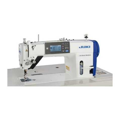
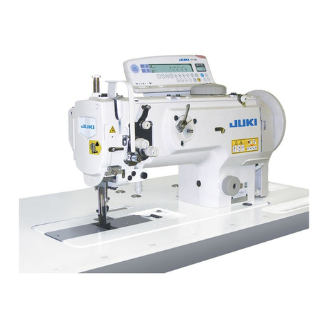
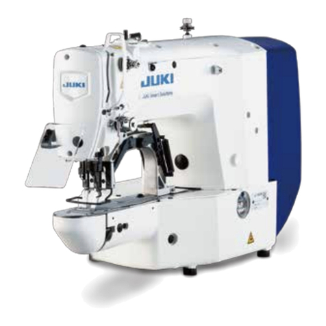
JUKI MO-644DN User manual

MO-644DN/654DEN
2-Needle, 2/3/4-Thread Overlock Sewing Machine
INSTRUCTION MANUAL
EN
IMPORTANT:
Read all safety regulations carefully and under-
stand them before using your sewing machine.
Retain this instruction manual for future reference.
MO-644DN
MO-654DEN

“IMPORTANT SAFETY INSTRUCTIONS”
When using an electrical appliance, basic safety precautions should always be followed, including
the following: Read all instructions before using this sewing machine.
“DANGER ____ To reduce the risk of electric shock:”
1. The appliance should never be left unattended when plugged in.
2.
Always unplug this appliance from the electric outlet immediately after using and before cleaning.
“WARNING ____ To reduce the risk of burns, re, electric shock, or injury to persons:”
1. Do not use the appliance as a toy. Caution is advised when the appliance is used by children, or
near children. This sewing machine can be used by children aged from 8 years and above and
persons with reduced physical, sensory or mental capabilities or lack of experience and knowl-
edge if they have been given supervision or instruction concerning use of the sewing machine
in a safe way and understand the hazards involved. Children shall not play with the sewing
machine. Cleaning and user maintenance shall not be made by children without supervision.
2. Use this appliance only for its intended use as described in this manual. Use only attachments
recommended by the manufacturer as contained in this manual.
3. Never operate this appliance if it has a damaged cord or plug, if it is not working properly, if it
has been dropped or damaged, or dropped into water. Return the appliance to the nearest au-
thorized dealer or service center for examination, repair, electrical or mechanical adjustment.
4. Never operate the appliance with any air openings blocked. Keep ventilation openings of the
sewing machine and foot control free from the accumulation of lint, dust, and loose cloth.
5.
Keep ngers away from all moving parts. Special care is required around the sewing machine needle.
6. Always use the proper stitch plate. The wrong plate can cause the needle to break.
7. Do not use bent needles.
8. Do not pull or push fabric while stitching. It may deect the needle causing it to break.
9. Do not carry out sewing with a marking pin stuck in the material since doing so can cause knife/
needle breakage. In addition, do not attempt to cut anything other than fabric and thread with
the upper/lower knives.
10. Switch the sewing machine o “O” when making any adjustments in the needle area, such as
threading needle, changing needle, threading looper, or changing presser foot and the like.
11. Always unplug the machine from the electrical outlet when removing covers, when covers are
opened to thread the loopers, when lubricating or when making any other user servicing adjust-
ments mentioned in the instruction manual.
12. Never drop or insert any object into any opening.
13. Do not use outdoors.
14.
Do not operate where aerosol (spray) products are being used or where oxygen is being administered.
15. To disconnect, turn all controls to the o “O” position, then remove plug from outlet.
16. Do not unplug by pulling on cord. To unplug, grasp the plug, not the cord.
17. Basically, the machine should be disconnected from the electricity supply when not in use.
18. If the supply cord is damaged, it must be replaced by the manufacturer, its service agent or sim-
ilarly qualied persons in order to avoid a hazard.
19. (Except USA/Canada) This machine is provided with double insulation.
Use only identical replacement parts. See instructions for servicing Double-Insulated machine.
“SERVICING DOUBLE-INSULATED PRODUCTS
(Except USA / Canada)”
In a double-insulated product, two systems of insulation are provided instead of grounding. No
grounding means is provided on a double-insulated product nor should a means for grounding be
added to the product. Servicing a double-insulated product requires extreme care and knowledge
of the system and should only be done by qualied service personnel. Replacement parts for a
double-insulated product must be identical to those parts in the product. A double-insulated product
is marked with the words DOUBLE INSULATION or DOUBLE INSULATED.
The symbol may also be marked on the product.
“SAVE THESE INSTRUCTIONS”
“This overlock sewing machine is intended for household use only.”
1
Danger warning
which is not speci-
ed
There is a risk of
electrical shock
There is a risk
of re
There is a risk of
injury to hands,
etc.
Prohibited matter
which is not speci-
ed
Disassembly/
alteration is pro-
hibited
Do not place
ngers under
the needle
Do not pour oil,
etc.
Generally required
behavior
Disconnect the
power plug
Congratulations on your purchase of a JUKI sewing machine.
Please be sure to read safety precautions in “To use the sewing machine safely” in the Instruction
Manual before use to fully understand the functions and operating procedures of the sewing
machine so as to use the sewing machine for a long time.
After you have read the Instruction Manual, please be sure to keep it together with the warranty so
that you can read it whenever necessary.
To use the sewing machine safely
Marks and pictographs included in the Instruction Manual and shown on the sewing machine are
used so as to ensure safe operation of the sewing machine and to prevent possible risk of injury to
the user and other people.
Warning marks are used for dierent purposes as described below.
WARNING Indicates that there is a possible risk of death or serious injury if this mark is ignored and the sewing machine
is used in a wrong manner.
CAUTION
Indicates the operation, etc. which can cause a possible risk of personal injury and/or physical damage if this mark
is ignored and the sewing machine is used in a wrong manner.
Pictographs mean the following:
2

● Do not wipe the sewing machine with solvent
such as thinner.
When the sewing
machine is soiled, put a
small quantity of neutral
detergent on a piece of
soft cloth and carefully
wipe o the sewing
machine with it.
● Be sure to use the sewing machine in the
temperature range from 5ºC to 40ºC.
If the temperature is excessively low, the
machine can fail to operate normally.
WARNING
For the combination of the material and the thread and needle, in particular, refer to the explanation
table in “Replacement of the needle”.
If the needle or thread does not match the material used such as in the case that an extra heavy-
weight material (e.g., denim) is sewn with a thin needle (#11 or higher), the needle can break result-
ing in an unexpected personal injury.
Other precautions
● Do not put the sewing machine under the
direct sunlight or in a humid place.
Be aware that the following state can take place since the sewing machine incorporates semi-con-
ductor electronic parts and precise electronic circuits.
* The operating temperature of the sewing machine is between 5ºC and 40ºC. Do not use the
sewing machine under the direct sunlight, near the burning things such as a stove and candle, or
in a humid place. By so doing, the temperature in the interior portion of the sewing machine can
rise or the coating of the power cord can melt, causing re or electrical shock.
LED light
・
Rated Voltage: 9V
・
Maximum power consumption: 1.3W
3

Safety instructions ·····································1-3
Contents···················································· 4
Details of the machine································ 5,6
• Accessories············································· 6
Assembling thread stand ····························7-8
Preparing the machine ································· 9
• Attaching the foot controller ························ 9
• On/O of the power/light switch ··················· 9
Operation and function
• Handwheel (Pulley)··································10
• Opening and closing the looper cover ··········10
• Opening and closing the cloth plate ·············10
• Presser foot lifter ····································· 11
• Changing the presser foot ························· 11
• Raising the upper knife ·····························12
• Lower knife adjusting knob ························12
• Stitch length adjusting knob ·······················13
• Dierential feed adjusting knob···················13
• Overlocking width selection knob ················14
• Presser foot pressure adjusting screw··········14
• Changing the needles·······························15
Threading
• Preparation ············································16
• 1. Upper looper thread (Blue) ····················17
• 2. Lower looper thread (Red) ················ 18-19
• 3. Right-hand needle thread (Green) ···········20
• 4. Left-hand needle thread (Yellow) ·············21
3-thread overlocking
• 4 mm wide 3-thread Overlocking·················22
• 6 mm wide 3-thread Overlocking·················22
Contents
2/3-thread converter
• How to use the 2/3 thread converter ············23
Trial sewing
• After threading, make a trial sewing ·············24
Thread tension dial ··························· 24
Adjusting the thread tension·············· 25
Roll hemming
• Roll hemmer···········································26
• Preparation for roll hemming ······················26
•
Standard thread tension list for roll hemming
···26
Sewing in tape ································· 27
Dierential feed (MO-654DEN)
• Dierential feed·······································28
Gathering (MO-654DEN)
• Gathering···············································29
• Unpicking seams ·····································29
Thread breakage during sewing ········· 30
Securing seams ······························· 30
Maintenance
• Changing the upper knife ··························31
• Changing the lower knife···························31
• Cleaning and lubricating····························31
• Before you call for help: Trouble and corrective
measures ··············································32
Specications ·································· 33
Optional Accessories ························ 34
4

View with looper cover open
Details of the machine
Looper cover opening handle
Looper cover
Cloth plate
Chip guard cover
Throat plate
Presser foot
Presser foot lifter
LED light
Thread take-up cover
Thread guide plate
Presser foot adjusting screw
Retractable support rod
Thread guide
Open thread guide
Presser foot lifter
Left-hand needle thread tension dial
Right-hand needle thread tension dial
Spool holder pin
Anti-vibration cone
Spool holders
Stitch length adjusting knob (MO-654DEN)
Differential feed adjustting knob (MO-
654DEN)
Machine socket
Handwheel (pulley)
Power/light switch
Lower looper thread tension dial
Upper looper thread tension dial
CAUTION :
Be sure to turn off the power switch before
opening the looper cover.
5
Upper looper
Lower knife
Lower looper
Lower knife setscrew
Lower looper threader (MO-654DEN)
Overlock width selection knob
Upper knife

Accessories
View with cloth plate open
Details of the machine
Foot controller Needle in the needle box
Small screwdriver
Large screwdriver (MO-654DEN)
Oiler
Accessory bag
Dust cover
Looper threader (MO-644DN)
Lower knife (MO-654DEN)
2/3 thread converter
(MO-654DEN)
Nets
Spool caps
Tweezers
Cleaning brush
Needle threader (MO-654DEN)
6
Lower knife adjusting knob
Stitch length adjusting knob (MO-644DN)
Differential feed adjusting knob (MO-644DN)

Assembling thread stand
Raise the support rod fully
Turn the thread stand until it engages the positioning stopper (A)
with a click.
Put the thread guide on the support rod
Insert the thread guide into the tip of the support rod so that the ar-
row in the thread guide comes in front of you.
Attaching the spool holders
Attaching the separately packed spool holder (equipped with two
spool holders) to the fixed spool holder.
A
7

Assembling thread stand
For overlock spools
For large spools
For spools of large inside diameter, position the anti-vibration come
upside down.
For small house-use spools
When using house-use spools, remove the anti-vibration cones.
Place a spool on the spoolholder with its notch downward and push
the spool caps on with the rounded outside edge at the bottom.
Notch
8

Preparing machine
1
2
3
A
B
C
Attaching the foot controller
1. Plug foot controller into machine socket.
2. Plug foot controller into power supply socket.
3. Lay your foot on the foot controller.
Step on the foot controller strongly (deeply), and the sewing
speed increases.
Step on the foot controller lightly (shallowly), and the sewing
speed decreases.
On/O of the power/light switch
A Pressing turns the power switch off.
B Pressing turns the power switch on, and sewing operation is per-
formable. The sewing light remains off.
C Pressing turns on both the power switch and sewing light.
MO-654DEN
MO-644DN
On/O of the power/light switch
The power/light switch is conveniently placed on the handwheel side
of the machine in front of the socket.
= Off
= On with light
CAUTION :
Perform these following steps when you are not using your
sewing machine:
1. Be sure to turn OFF the power switch.
2. Be sure to remove the power plug from the wall outlet.
3. Do not place a thing on the foot controller.
CAUTION :
Perform these following steps when you are not using your
sewing machine.
1. Turn the power/light switch off. (Press side).
2. Be sure to remove the power plug from the wall outlet.
3. Do not place a thing on the foot controller.
CAUTION :
Be sure to turn OFF the power switch before plugging/un-
plugging the controller.
9

Operation and function
Handwheel (Pulley)
The handwheel turns toward you.
* Upon completion of threading, at sewing start or sewing end, be
sure to turn the handwheel toward you.
Opening and closing the looper cover
Opening: To open the looper cover, pull the looper cover opening
handle to the right, and tilt the looper cover toward you.
Closing: To close the looper cover, push up the looper cover, press
it lightly to the right. The looper cover closes automatical-
ly.
Opening and closing the cloth plate
Opening: Press the cloth plate toward the outside.
Closing: Push the cloth plate toward the sewing machine.
CAUTION :
[ MO-654DEN ]
For safety, the power is automatically cut off when you
open the looper cover or the cloth plate.
CAUTION :
[ MO-654DEN ]
For safety, the power is automatically cut off when you
open the looper cover or the cloth plate.
Switch the machine off (power switch ”O”)
10

Changing the presser foot
Be sure to turn the power switch OFF.
1. Raise the presser foot.
2. Turn the handwheel until the needles are fully raised.
3. Press point (C) illustrated in the figure, and the presser foot will
be released.
4. To release the presser foot, raise the presser foot lifting lever to
its highest position. Then you can release the presser foot easily.
5. To attach the presser foot, place it so that presser foot pin comes
exactly under the groove in the holder (D). Lower the presser
foot lifting lever and the presser foot will en gage automatically.
Operation and function
Presser foot lifter (To raise the presser foot by the presser foot lifter)
A For regular sewing operation (sewing a medium-weight material),
raise the presser foot to position (A) illustrated in the figure.
B When you sew a heavy-weight material, raise the presser foot to
position (B) illustrated in the figure, to provide more space be-
tween presser foot and throat plate.
A
B
WARNING :
When using the extra lift (B), do not run the machine or turn
the handwheel.
11

Lower knife adjusting knob
(adjusting the lower knife position for cutting width)
Be sure to turn the power switch OFF.
Turn the lower knife adjusting knob by pressing part (C) in the fig-
ure.
• (E): If the edge of the sewing materialcurls, set the lower knife ad-
justing knob (D) to smaller value on the scale.
• (F): If the remaining thread is too long for the edge of the material,
set the lower knife adjusting knob to larger value on the scale.
Operation and function
C
D
E F
Raising the upper knife
Be sure to turn the power switch OFF.
1. Turn the handwheel until the upper knife is fully raised. Open the
looper cover.
2. Press the part indicated as (A) in the figure toward the right until
it will go no further.
3. Keep pressing (A) and turn the knob on the right side in the di-
rection of the arrow.
4. Turn the knob until the knife reaches position (B).
A
B
12

Operation and function
Stitch length adjusting knob (to adjust the stitch length)
Stitch length is adjustable within the range from 1 to 4.
To adjust the stitch length, turn the stitch length adjusting knob and
move the knob upwards or downwards.
* For normal overlocking stitches set the stitch length adjusting knob
at 2 to 3.
Dierential feed adjusting knob
(to adjust the feeding for gathering or stretching)
To adjust feeding for gathering or stretching, turn the dierential feed
adjusting knob upward or downward.
The dierential feed prevents uting or waving in seams in stretchy
materials by dierentiating the feed of the front feed dog (A) and rear
feed dog (B).
MO-644DN
MO-654DEN
MO-644DN
MO-654DEN
BA
MO-644DN
MO-654DEN
MO-644DN
MO-654DEN
BA
13

Operation and function
Overlocking width selection knob
(for overlocking or roll hemming)
* Turn the handweel until the needles are fully raised.
• For overlocking:
Push the overlocking width selection knob back so that it aligns
with the rear red marking on the throat plate.
• For roll hemming:
1. Pull the overlocking width selection knob forward so that it
aligns with the front red marking on the throat plate.
2. Set the lower knife adjusting knob at “1 - 2”.
Presser foot pressure adjusting screw
Pressure of the presser foot has been factory-adjusted properly.
Therefore you do not need to adjust it except when sewing a special
material.
• To increase the pressure of the presser foot:
For heavy-weight materials such as denim,
tweed, or hard linen.
• To decrease the pressure of the presser foot:
For light-weight materials such as geor-
gette, lawn,or tricot.
(A) Standard position: The place where the lower part of control
cap aligns with the upper face of cover.
IncreaseDecrease
A
14

Operation and function
A
Needles used Type of needles Thickness
Right-hand needle Household type
130/705H No.75/11
Left-hand needle 130/705H (JL × 2)
* When you buy the needles for the sewing machine, select the
above type of the needles.
* Apply a JL × 2 needle to the left-hand side needle when sewing
heavy-weight materials.
Changing the needles
Be sure to turn the power switch OFF.
• Applying the needle attaching hole (A) of the cleaning brush will
help replace the needle ease.
1. Turn the handwheel until the needle are fully raised.
2. Before Changing the needles, lower or remove the presser foot.
3. Using the small screwdriver, loosen the needle setscrews and re-
move the needles.
4. First insert the right-hand needle with the flat side away from you
into the needle clamp, making sure it is inserted as far up as pos-
sible. Tighten the needle clamp setscrews securely. Insert the left-
hand needle in the same way.
15

Threading
Thread the machine carefully and in the correct sequence. This is important for marking beautiful seams.
Preparation
1. Retractable support rod with thread guide must be fully raised.
2. Open the looper cover and cloth plate.
3. Turn the handwheel toward you until the needles are fully raised.
4. Raise the upper knife.
Threading sequence
Colored threading illustrations affixed clearly show the threading sequence.
Thread the machine in the following sequence:
1. Upper looper thread (Blue)
2. Lower looper thread (Red)
3. Right hand needle thread (Green)
4. Left hand needle thread (Yellow)
Threading aids such as tweezers, needle threader, and looper threader which are provided as accessories will be very
useful in threading work.
Thread the tension dials
To lay the thread correctly between the tension discs, pull the thread
lightly with both hands.
Needle threader
Insert the needle threader through the needle eyelet or looper eye-
let, then thread the needle threader. Now pull the needle threader
back until it comes of the eyelet.
Be sure to turn the power switch OFF.
16

Threading (1)
1. Upper looper thread (Blue)
Place the spool on the spool holder pin right under blue marking on
the retractable support rod thread guide.
(1) Bring thread up from the rear of the retractable support rod thread
guide with blue marking.
(2,3) Pass the thread through the thread guide plate.
(4) Bring the thread on to the thread guide.
(5) Lay the thread between the thread tension dial discs.
(6,7,8,9,10,11) Thread the thread guides.
(12) Turn the handwheel until the upper looper is fully raised.
Thread upper looper eye.
(13) Pull about 10 cm of the thread out.
Place the thread under the presser foot, and pull the thread
frombehind the presser foot.
Use a net for a hard twisted thread
When a thread coils around the thread guide due to its hard twist,
cover the spools of upper looper and lower looper with attached nets.
MO-644DN/654DEN
17

2. Lower looper thread (Red)
Place the spool on the spool holder pin right under red marking on
the retractable support rod thread guide.
(1,2) Bring thread up from the rear of the retractable support rod
thread guide to the front of it.
(3,4) Pass the thread through the thread guide plate.
(5) Bring the thread on to the thread guide.
(6) Thread the thread tension dial.
(7,8,9,10,11) Thread the thread guides.
(12) Raise the needle fully and press the lever of the threading de-
vice down.
MO-654DEN only:
(13,14) Thread the guide and then the slit on the device. Holding
the thread loosely with the left hand, turn the handweel until
upper and lower loopers just cross. The threading device
will automatically return to the normal position.
(15) Thread the lower looper eye and place thread under the press-
er foot.
* If the lower looper thread is broken or slipped, cut the both needle
threads off at the needle. Then remove the thread.
Thread the lower looper and then the needles.
Threading (2) MO-654DEN
18

MO-644DN only:
(13) Using the looper threader, pass the threader from the right through to the left of the sewing machine. Turn the
handwheel toward you until the lower looper is in the left-most position. Insert the thread into the slit on the lower
looper.
(14) Using the looper threader, pull the thread through to the right side again. Turn the handwheel toward you until the
lower looper is in the right-most position, and thread the looper eye. Pull the thread up until it lies in the long groove
on the lower looper.
(15) Pull about 10 cm of the thread out through the upper looper. Raise the presser foot, place the thread under it and
then lower the presser foot.
* If the lower looper thread is broken or slipped, cut the right and left-hand needle threads off at the needle. Then
remove the threads. Thread the lower looper and then the needles.
Threading (2) MO-644DN
1
3
4
5
6
7
8
9
10
11
12
13
14
15
213
13
14
12
11 10
19
This manual suits for next models
1
Table of contents
Other JUKI Sewing Machine manuals

JUKI
JUKI SC-922 User manual

JUKI
JUKI DDL-8700-7 User manual

JUKI
JUKI DNU-1541 Quick start guide

JUKI
JUKI LU-1510 Quick start guide

JUKI
JUKI LU2-4652-B1T User manual

JUKI
JUKI AMB-289/IP-420 User manual

JUKI
JUKI DSC-244 User manual

JUKI
JUKI LK-1900AN-SS User manual

JUKI
JUKI DLN-9010 User manual

JUKI
JUKI MO-644D User manual

JUKI
JUKI AMS-221EN-HS3020/7200 User manual

JUKI
JUKI LU-2810 Series User manual

JUKI
JUKI MO-6800S Series User manual

JUKI
JUKI AMB-289 User manual

JUKI
JUKI LBH-1790 Series User manual

JUKI
JUKI AMS-210EN/IP-420 User manual

JUKI
JUKI MOL-254 User manual

JUKI
JUKI MB-372 User manual

JUKI
JUKI HZL-355ZW-A User manual

JUKI
JUKI MH-481 User manual