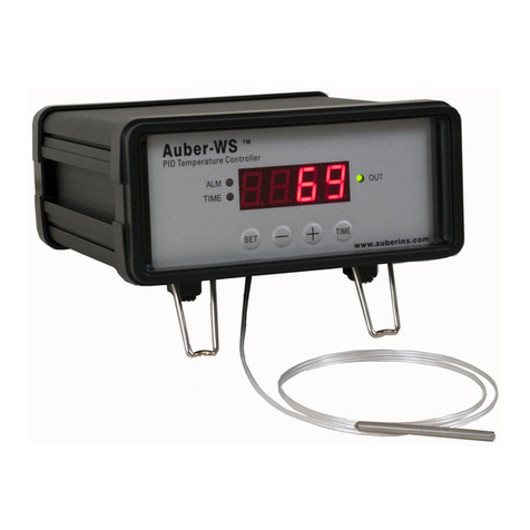
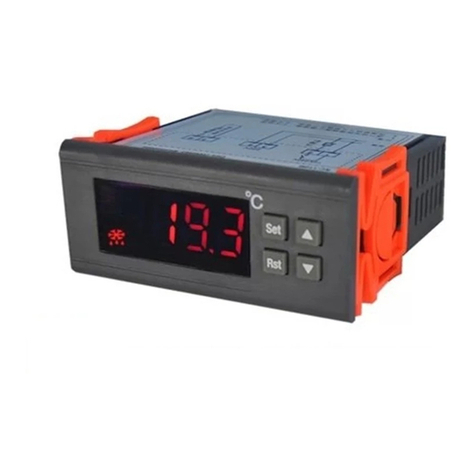
One sensor wire/two plastic supports/one user maual
In heat mode:
A. Heating systems works in below situation:
The measuring temperature ≤ the set temperature - the temperature difference;
B. Heating systems stop working in below situation:
The measuring temperature ≥ the set temperature
3. Delay Time:
HS and LS can set the high and low limit of the setting temperature:
For example: HS is +15, LS is -10, the temperature only can be set between -10~+15℃;so if
you want to set a value beyond this range, please reset the HS and LS firstly.
4. High and low temperature limit:
1. Sensor error alarm
2. Over temperature alarm
10A/250V
124567
Sensor
22 0V
50/60HZ
Power
Load
3
Wiring Diagram
Accessary
Error Code
In cool mode:
A. Cooling systems works in below situation:
The measuring temperature ≥ the set temperature + the temperature differential
B. Cooling systems stop working in below situation:
The measuring temperature ≤ the set temperature
2. Cool and Heat Function:
When power on for the first time, if The measuring temperature ≥ the set temperature + the
temperature differential or The measuring temperature ≤ the set temperature - the
temperature difference, the output will not be activated immediately, and will be activated after
the delay time.
When the controller is in power on status,if sensor open circuit, LED flash and display “
_ _”,if sensor short circuit, display “HH”. When in sensor error status, the output load will run as
the cycle: stop 15 minutes, then work 15 minutes.
When the sensor temperature>99℃,display HH;When the sensor temperature<-40℃,
display LL.
Page2/2
1.Before use, please carefully read the user manual, must distinguish the functions of the different
contact points. The connected load power should not exceed the capacity of contact point (if
exceeding, please connect AC contactor). Each connecting wire should be connected to the
terminals firmly.
2.Please install the device firmly in a stable place, avoid crash. The device cannot be placed with
dripping or water, and keep away from the electromagnetic interference of the electrical apparatus.
3.In order to prevent the interference of high frequency, the sensors and low voltage lines cannot
parallel and be bundled up with high voltage line. The diameter of the high voltage wire must be
between 0.75 mm and 1.5mm.
4.If the device is disturbed, please cut off the power, and restart. This software belongs to class A,
which is not applicable to safety protection control.
5.Do not privately disassemble the device. If faults occur or have questions of the usage, please
contact our company.
Installation notes:
If the time period between the previous stop and this starts is longer than the delay time, the
output will be activated immediately; if it is shorter than the delay time, the output will be
activated after the delay time. The delay time is calculated from the previous output stop.
Normal
Close
