RioOutdoors 4P-DC User manual

1 | Page
Installation Instructions
4P-DC
4x4 Post-in-Ground Double Cubic Pergola Kit
Pergola Kits
WARNING: If the information in these instructions is not followed exactly, weakening or failure of the erected
structure may result causing property damage, personal injury, or loss of life.
All brackets designed and sold by RioOutdoors.com are to be used for building pergolas only and are not to be used for
other structure construction purposes.
•
Thoughtfully engineered
Brackets eliminate all wood-
joinery skills requirements.
•Skills required: footing &
post install, drilling pilot
holes and driving lag
screws into lumber.
•Easy lift and place U-
channels eliminate need
for lifting equipment.
Super-easy assembly
work.
•Self-aligning design
squares up structure
automatically.
•Estimated Assembly
Time is less than 1 hour
(after posts are
installed).
Figure 1: Items included in the kit, (
).
Items not included in this kit: wood, tools, some hardware.

2 | Page
Table of Contents
SAFETY AND WARNING INFORMATION........................3
TOOLS REQUIRED...................................................4
CONTENTS OF KIT #4P-DC......................................5
LIST OF MATERIALS THAT YOU WILL SUPPLY ..................5
POST-IN-GROUND SYSTEM .......................................6
SIDE ELEVATION DIAGRAM....................................... 9
POST-TOP BRACKETS INSTALLATION ........................ 10
POST TOP 2-WAY EXTENSION BRACKET INSTALLATION 13
4X4HEADERS INSTALLATION ................................. 15
CONDITIONS ...................................................... 18
EXCLUSIONS....................................................... 18
LIMITATIONS OF LIABILITY ..................................... 19
HOW TO OBTAIN WARRANTY SERVICE ..................... 19
Proper pilot hole diameter and hole depth for various lag screws and wood types
Lag Screw Type
Wood Type
Pilot hole drill diameter and hole depth
¼” X 1-1/4” Lag Screw
McMasterCarr.com SKU 92351A546
Soft Wood 3/32” drill bit diam., 1-1/4” depth
Hard Wood 3/16” drill bit diam., 1-1/4” depth
3/8” X 3” Lag Screw
McMasterCarr.com SKU 92351A636
Soft Wood
11/64” drill bit diam., 3” depth
Hard Wood ¼” drill bit diam., 3” depth
A properly sized pilot hole must be drilled before you attempt to drive lag screws into any pergola lumber member.
See Table, below. Driving lag screws into lumber, without first drilling a pilot hole, can prevent the lag screw from
driving fully into the wood or can lead to crack formation while driving the lag screw in, or later, as the wood dries
naturally. This can result in a weakened pergola structure.

3 | Page
GENERAL INFORMATION
SAFETY AND WARNING INFORMATION
1.1.1 Building Permit & Inspection Requirements
We recommend that you consult with your local building permit office and obtain advice and any required building permits and
inspection approvals from the local building inspection department or the local jurisdiction having authority over building codes.
1.1.2 Other Cautions
CAUTION: Adhere to all safety requirements. Wear safety glasses/goggles when working. Wear safety gloves
when handling brackets, hardware, and lumber. Wear hearing protection when using a circular saw, miter
saw, table saw, or hammer drill.
INSTALLER: Leave this manual with the consumer. CONSUMER: Retain this manual for future reference.
4 | Page
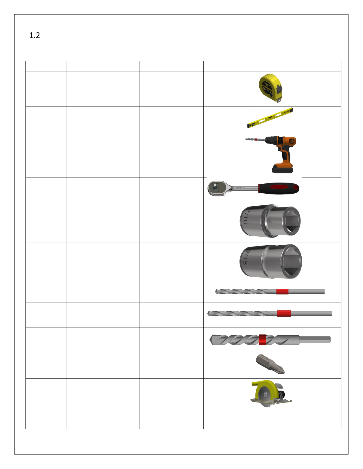
TOOLS REQUIRED
Listed below, are common tools required for pergola projects. These tools are not included in this kit. Your pergola project may
not require all tools. Select and acquire the tools for your project from the “Required for” column in this table.
Description
Tool Purpose
Required for
Reference Image
Tape
Measure
Measure and verify
lengths. All pergola types
Framing
Level Verify Level/Plumb All pergola types
Hammer
Drill
Drill holes in concrete
pads or concrete footing
for securing floor anchor
brackets. Drill pilot holes
for lag screws.
All pergola types
Ratchet
Socket
Driver
Drive lag screws into
Pergola lumber members. All pergola types
7/16” Hex
Socket
Drive ¼” X 1-1/4” Hex Hd.
lag screws. All pergola types
9/16” Hex
Socket
Drive 3/8” X 3” Hex Hd.
lag screws.
Raftered pergola
(single, dual, quad
headers)
3/32” Drill
Bit
Drill pilot holes for ¼” lag
screws in soft wood. All pergola types
11/64” Drill
Bit
Drill pilot holes for 3/8”
lag screws in soft wood.
Raftered pergola
(single, dual, quad
headers)
½” X 4”
Masonry
Drill Bit
Drill ½” X 2” deep holes in
concrete pads or
concrete footings.
Surface Mount styled
pergola
#2 Phillips
Screwdriver
Bit
Attaching pergola rafter
ties to rafters and
headers.
Raftered pergola
(single, dual, quad
headers)
Circular
Saw/Miter
Saw
Cut headers to length; cut
rafters to length. All pergola types
Jig Saw
Optional. Cut rafter tail
designs. Raftered pergolas Image not available.

5 | Page
CONTENTS OF KIT # 4P-DC
The contents of this kit are shown in the table, below. Before you begin your project, take an inventory of all items that you
received from us. If any items are missing, contact us directly via email at info@RioOutdoors.com. Include your name and
shipping address and your order number, if available. We will respond within 24 hours with a resolution to your problem.
Item SKU #, Description
Item Qty
Item Image
4x4 Post-Top/Floor 2-way Elbow Bracket
SKU# 4C2L 4
4x4 Post-Top/Floor 2-Way Straight Extension
SKU #4SE 2
¼ x 1-1/4” Lag Screw
72
LIST OF MATERIALS THAT YOU WILL SUPPLY
This is the list of required materials which are not included in this kit. You will acquire these items locally for your project. Use
this table to help you calculate your total project budget.
Item Description Item Qty Item Cost ($)
Total Item
Cost ($)
4x4 Post Lumber (You determine length) 4
4x4 Header Lumber (You determine length)
6
Tape, for marking drill bit depth
2”
Grand Total Cost ($)

6 | Page
POST-IN-GROUND SYSTEM
1.5.1 What is a Post-in-Ground anchoring system?
As the term indicates, Post-in Ground, means that the vertical posts for a pergola are inserted deep into concrete footings and
anchored in that way. The depth of the footing and the length of the post required to be embedded into the footing is
determined by the maximum depth of the frost line for a particular area. The diameter of the footing is determined by the
weight each post applies to the footing. If you add headers, a swing or hammock, you must consider the additional weight.
Consult your local building codes to determine the required footing depth and diameter. If you fail to follow local guidelines and
create a footing that is too shallow, it can lead to the post and footing heaving upward when the ground freezes during the
winter. This can permanently damage the Pergola and render it unsafe for use.

7 | Page
1.5.2 Study the posts layout requirements.
First, study the posts layout requirements. Spend some time planning, yourself, so you are fully familiar with the final size you
desire for your poergola.The lengths of the headers will determine the post center locations. Use the table, below, and the general
guidelines to determine the post center locations.
Determine the exact location for each pergola post center based on your pergola size. We have designed our pergola systems to
eliminate the need to cut any 4x4 post or header members. Plan accordingly to minimize your work requirements.
Mark each post center location using wood stakes or bright colored spray paint. Remeasure and verify the proper location for each
post.
1.5.2.1 General Guidelines for post center locations
The distance between post centers equals the length of the header between the two posts plus 3-3/4”. If the header length you
chose is not listed in the table, above, use this general guideline to determine the post center locations.
DIM A
DIM B
DIM C
DIM D
DIM E
DIM F
OVERALL
WIDTH
OVERALL
LENGTH
96
99 3/4
96
99 3/4
96
99 3/4
103 1/2
203 1/4
108
111 3/4
108
111 3/4
108
111 3/4
115 1/2
227 1/4
120
123 3/4
120
123 3/4
120
123 3/4
127 1/2
251 1/4
132
135 3/4
132
135 3/4
132
135 3/4
139 1/2
275 1/4
144
147 3/4
144
147 3/4
144
147 3/4
151 1/2
299 1/4

8 | Page
1.5.3 Call 811.
811 is the national call-before-you-dig phone number. Anyone
who plans to dig should call 811 or go to their state 811
center's website before digging to request that the
approximate location of buried utilities be marked with paint
or flags so that you don't unintentionally dig into an
underground utility line.
Consult with your local building permit office and obtain any
required building permits and formal information related to
required footing depth and diameter for your locality.
1.5.4 Install the Post-in-Ground footing
system.
1. Excavate the required hole diameter and depth. Dig
down an additional 6” in depth.
2. Fill the bottom 6” with loose gravel. The loose gravel
will help keep water from pooling at the bottom of
the post and will prevent rotting of the post bottom.
3. Set each post on top of the gravel. Level each post.
Support the post using cross 2x4 members or other
means.
4. Use a laser level to see if the post heights vary
among all posts. All posts top should be on the same
plane. If a post is too low, add more gravel under the
post to lift the post up. If a post is too high, remove
some gravel and lower the post.
5. Once all posts are level and all posts’ top surfaces
are on the same plane, pour the concrete around the post.
6. Work in 6” incremental depths. Tap concrete with the tip of
a trowel to remove air bubbles. Work upward until you
reach ground level or 1” below ground level, depending on
your desired final finish appearance. You may stop 1” below
the surface so you can over fill with some dirt and plant
grass around the post or you may fill all the way up to
ground level.
7. At this point, create downward tapered profile moving away
from the post in all directions on the concrete top surface.
This taper will help water flow away from the post.
8. Wait 7 days for the concrete footing to cure before
proceeding with the remaining construction work. If quick-
setting concrete is used, cure times may be shorter; read
the information on the concrete bag or ask your concrete
supplier.

9 | Page
SIDE ELEVATION DIAGRAM
Based on the height of the post used, the diagram below provides the side elevation profile for this pergola system.
POST HEIGHT
DIM A
DIM B
96
96
92.5
108
108
104.5
120
120
116.5
132
132
128.5
144
144
140.5
Dim A, above, is the height of the post used. Dim B is the inner ceiling height of the pergola. Dim B is measured to the bottom
surface of the header member.

10 | Page
POST-TOP BRACKETS INSTALLATION
1. Slide the 2-way elbow bracket’s tube over the 4x4 post top after aligning the header receiver u-channels in the proper
direction. Let gravity work and pull the bracket all the way down on top of the post.
2. Identify the four 5/16” holes which are on the sides of the gussets in the bracket.

11 | Page
3. Wrap a piece of electrical tape around the drill bit, spaced 1-1/4” from the drill bit tip. This will act as a hole depth indicator
when you drill each pilot hole. Pilot holes should be drilled at least 1-1/4” deep. A little bit deeper is acceptable but do not
drill less than the required 1-1/4” depth.
4. Drill 3/32” X 1-1/4” deep pilot holes at the center of four 5/16” Holes. Locate pilot holes at the center of each 5/16”
hole.

12 | Page
5. Drive one ¼ x 1-1/4” Hex Lag Screw through each 5/16” hole into the pilot holes you drilled in step 4, using a 7/16”
Socket and Rachet driver. Tighten down each screw.
6. Repeat steps 1 through 5 for each post top bracket.

13 | Page
POST TOP 2-WAY EXTENSION BRACKET INSTALLATION
The post-top extension bracket is to be mounted to the top of the middle support post. It will receive two headers running in
opposing directions.
1. Orient the post-top 2-way extension bracket’s U-channels in the desired direction and slide the square tube over the top
of the center post. Let gravity pull it down. If it resists, tap the top lightly with a mallet.
2. Locate two 5/16” holes on two opposing sides of the tube, adjacent to the gussets (4 holes total). Drill 3/32” x 1-1/4”
deep pilot holes in the center of the 5/16” holes.

14 | Page
3. Using a 7/16” socket and ratchet driver, drive a ¼” X 1-1/4” Lag Screw through each pilot hole you drilled.

15 | Page
4X4 HEADERS INSTALLATION
1. Lift and place one 4x4 header into the U-channels of adjacent post-top brackets.
2. Locate the two 5/16” holes on each vertical face of the U-channels holding the 4x4 header. Drill 3/32” X 1-1/4”
deep pilot holes at the center of four 5/16” Holes. Locate pilot holes at the center of each 5/16” hole.

16 | Page
3. Drive one ¼ x 1-1/4” Hex Lag Screw through each 5/16” hole into the pilot holes you drilled in step 8, using a 7/16”
Socket and Rachet driver. Tighten down each screw.
4. Repeat steps 1-3 for all headers.

17 | Page
Your Cubic Pergola construction project is now complete. Let us know how the construction project went for you.
Was it easy to do? Did parts fit easily and properly? Do you like the quality of our products and design styles? Is
your pergola structure sturdy and strong? Please go to RioOutdoors.com and provide us with your review.
Thank you for being a RioOutdoors.com customer.

18 | Page
WARRANTY POLICY STATEMENT
RioOutdoors.com, extends this 1-Year Warranty to the original purchaser, automatically upon purchase from RioOutdoors.com.
The items covered by this warranty and the period of such coverage is set forth in the table below.
Some conditions apply (see below).
The policy is not transferable, amendable, or negotiable under any circumstances.
Part 1 year
Labor
Coverage
Welded Steel Brackets
Not Included
Painted Finishes
Not Included
All hardware
Not Included
CONDITIONS
Warranty protects against defect in manufacture only, unless herein specified otherwise.
Any part(s) found to be defective during the warranty period as outlined above will be repaired or replaced at RioOutdoors.com’s
option provided that the defective part is returned, if requested by RioOutdoors.com. Alternatively, RioOutdoors.com may at its
own discretion fully discharge all its obligations under the warranty by refunding the verified purchase price of the product to the
original purchaser.
RioOutdoors.com is not responsible for results or costs of workmanship of installers in the negligence of their construction work.
At all times RioOutdoors.com reserves the right to inspect reported complaints on location in the field claimed to be defective
prior to processing or authorizing of any claim. Failure to allow this upon request will void the warranty.
All claims must be complete and provide full details as requested by RioOutdoors.com to receive consideration for evaluation.
Incomplete claims may be rejected.
All pergola brackets must be installed according to all manufacturers’ instructions as per the installation instruction manual by a
RioOutdoors.com.
All Local and National required codes must be met.
Repair/replacement parts purchased by the consumer from RioOutdoors.com after the original coverage has expired will carry a
90-day warranty, valid with a receipt only. Any item shown to be defective will be repaired or replaced at our discretion. No labor
coverage is included with these parts.
EXCLUSIONS
This 1-Year Warranty does not extend to paint, rust, or corrosion of any kind due to corrosive chemicals (i.e., chlorine, salt, air,
etc.), physical damage to painted surfaces during installation or later.
Malfunction, damage, or performance-based issues of all components as a result of environmental conditions, location, chemical
damages, downdrafts, installation error, installation by an unqualified installer, abuse, misuse, use of improper tools, acts of God,
weather related problems from hurricanes, tornados, earthquakes, floods, lightning strikes/bolts or acts of terrorism or war,
which result in damage are not covered under the terms of this 1-Year Warranty.
RioOutdoors.com has no obligation to enhance or modify any part once manufactured (i.e., as products evolve, field
modifications or upgrades will not be performed on existing pergolas).
Any parts showing signs of abuse or misuse will not be covered under the terms of this warranty policy and may void this
warranty. This includes parts with rusted or corroded surface or welds which have not been reported as rusted or corroded
within three (3) months of installation/purchase.

19 | Page
Parts which show evidence of being used while damaged, or with problems known to the purchaser and causing further damages
will void this warranty.
Parts where the RioOutdoors.com logo has been altered, deleted, removed, or made illegible will void this warranty.
Minor movement, expansion and contraction of the steel parts is normal and is not covered under the terms of this warranty.
Freight damages for parts are not covered under the terms of the warranty.
Products made or provided by other manufacturers and used in conjunction with the RioOutdoors.com parts without prior
authorization from RioOutdoors.com may void this warranty.
LIMITATIONS OF LIABILITY
The original purchaser’s exclusive remedy under this warranty, and RioOutdoors.com’s sole obligation under this warranty,
express or implied, in contract or in tort, shall be limited to replacement, repair, or refund, as outlined above. IN NO EVENT WILL
RioOutdoors.com BE LIABLE UNDER THIS WARRANTY FOR ANY INCIDENTAL OR CONSEQUENTIAL COMMERCIAL DAMAGES OR
DAMAGES TO PROPERTY. TO THE EXTENT PERMITTED BY APPLICABLE LAW, RioOutdoors.com MAKES NO EXPRESS WARRANTIES
OTHER THAN THE WARRANTY SPECIFIED HEREIN. THE DURATION OF ANY IMPLIED WARRANTY IS LIMITED TO DURATION OF THE
EXPRESSED WARRANTY SPECIFIED ABOVE. IF IMPLIED WARRANTIES CANNOT BE DISCLAIMED, THEN SUCH WARRANTIES ARE
LIMITED IN DURATION TO THE DURATION OF THIS WARRANTY.
Some U.S. states do not allow limitations on how long an implied warranty lasts or allow exclusion or limitation of incidental or
consequential damages, so the above limitations or exclusions may not apply to you.
Customers located outside the U.S. should consult their local, provincial, or national legal codes for additional terms which may
be applicable to this warranty.
HOW TO OBTAIN WARRANTY SERVICE
Customers should contact RioOutdoors.com by email at [email protected] . Please include a brief description of the
problem and your address, email, and telephone contact information. A representative will contact you to make arrangements
for warranty service.
Warrantor:
RioOutdoors.com
United States
Thank you for choosing RioOutdoors.com.
Table of contents
Other RioOutdoors Lawn And Garden Equipment manuals


Popular Lawn And Garden Equipment manuals by other brands

Sunforce
Sunforce SOLAR user manual

GARDEN OF EDEN
GARDEN OF EDEN 55627 user manual

Goizper Group
Goizper Group MATABI POLMINOR instruction manual

Rain Bird
Rain Bird 11000 Series Operation & maintenance manual

Cub Cadet
Cub Cadet BB 230 brochure

EXTOL PREMIUM
EXTOL PREMIUM 8891590 Translation of the original user manual


Vertex
Vertex 1/3 HP Maintenance instructions

GHE
GHE AeroFlo 80 manual

Land Pride
Land Pride Post Hole Diggers HD25 Operator's manual

Yazoo/Kees
Yazoo/Kees Z9 Commercial Collection System Z9A Operator's & parts manual

Premier designs
Premier designs WindGarden 26829 Assembly instructions

Snapper
Snapper 1691351 installation instructions