ECS B450AM4-M User manual

B450AM4-M USER MANUAL
i
TABLE OF CONTENTS
Preface i
Brief Introduction 1
Specifications......................................................................................1
Motherboard Components................................................................3
Header Pin Definition and Jumper Settings.........................................5
I/O Ports...............................................................................................8
Multi-language Quick Installation Guide 9
English...................................................................................................9
Simplified Chinese...............................................................................11
Korean......................................................................................................13
Indonesian.............................................................................................15
Japanese.................................................................................................17
Vietnamese.............................................................................................19

ii
B450AM4-M USER MANUAL
Memo
B450AM4-M USER MANUAL
1
Brief Introduction
CPU
Specifications
• AMD B450 ChipsetChipset
• Dual-channel DDR4 memory architecture
• 4 x 288-pin DDR4 Long-DIMM sockets support up to 64 GB
• Supports 2400 MHz DDR4 Long-DRAM (by CPU)
Memory
• 2 x PCI Express x16 slots (one slot runs x16 Gen3, the other
runs x4 Gen2)
• 1 x PCI Express x1 Gen2 slot
• 1 x PCI slot
• 2 x M.2 slot (socket 1 key E 2230 supports wifi + BT, socket 3 key
M 2242/2280 supports SSD/SATA)
• Supported by AMD B450 Chipset
- 4 x Serial ATA 6Gb/s devices
- RAID 0, 1, 10
Expansion
Slots
Storage
• 1 x PS/2 keyboard and PS/2 mouse connectors
• 1 x VGA port
• 1 x DVI port
• 1 x HDMI port
• 1 x DP port
• 2 x USB 3.1 ports
• 2 x USB 2.0 ports
• 4 x USB 3.0 ports
• 1 x RJ45 LAN connector
• 1 x Audio port (1x Line in, 1x Line out, 1x Mic_in Rear)
Rear Panel I/O
• Realtek RTL8111GN
- 10/100/1000 Fast Ethernet Controller
- Wake-on-LAN and remote wake-up support
•AMD®RYZENTM Series processors Gen2 for socket AM4
• Supports CPU up to 95W TDP
Note: Please go to ECS website for the latest CPU support list.
• 1 x 24-pin ATX Power Supply connector
• 1 x 4-pin 12V Power connector
• 1 x 4-pin CPU_FAN connector
• 2 x 4-pin SYS_FAN connectors
• 1 x Front Panel audio header
• 1 x Front Panel switch/LED header
Internal I/O
Connectors &
Headers
• Realtek ALC662
• Realtek ALC1304 Amplifier IC
- 6 Channel High Definiton Audio Codec
- Compliant with HD audio specification
Audio
LAN
Note: Please go to ECS website for the latest Menory support list.
Note: If HDMI and DP are connected simultaneously, the HDMI
will show preferentially.
B450AM4-M USER MANUAL
2
QR Code for the complete manual download
on ECS website: http://www.ecs.com.tw
• AMI BIOS with 128Mb SPI Flash ROM
- Supports Plug and Play, STR(S3)/STD(S4)
- Supports Hardware Monitor
- Supports ACPI & DMI
- Supports Audio, LAN, can be disabled in BIOS
- F7 hot key for boot up devices option
- Supports BIOS parameters copied to the flash disk
- Supports Pgup clear CMOS Hotkey (Has PS2 KB Model only)
System BIOS
Form Factor • Micro-ATX Size, 244mm x 244mm
• 1 x USB 3.1 Gen1 header supports additional two USB 3.0
ports
• 4 x Serial ATA 6Gb/s connectors
• 1 x 10-pin USB 2.0 header supports additional two USB 2.0
ports
• 1 x 5-pin USB 2.0 header supports additional one USB 2.0
port
• 2 x Serial port headers (COM)
• 1 x LPT header
• 1 x RGB header for AMD fan use
• 1 x CLR_CMOS jumper
• 1 x Case open header
• 1 x Speaker connector
B450AM4-M USER MANUAL
3
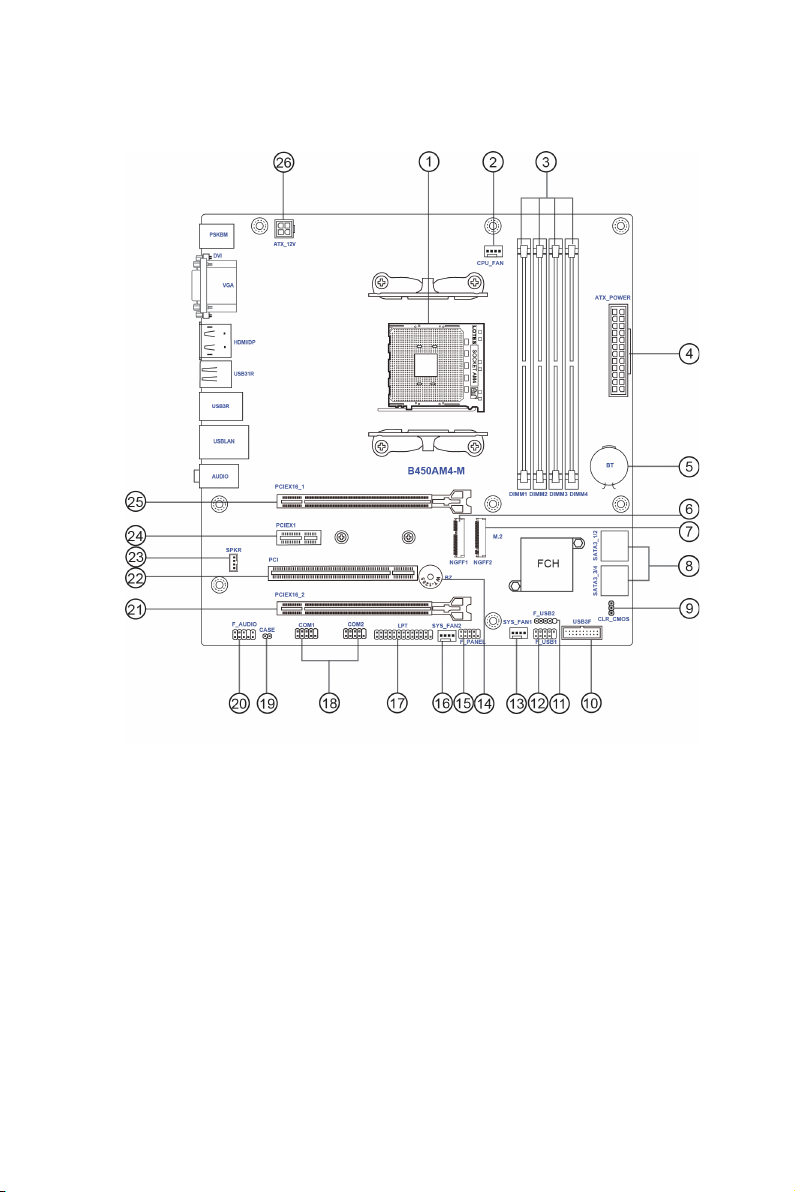
Motherboard Components

B450AM4-M USER MANUAL
4
Table of Motherboard Components
LABEL COMPONENTS
1. CPU Socket Socket AM4
2. CPU_FAN 4-pin CPU cooling fan connector
3. DIMM_1~4 288-pin DDR4 Module slots
4. ATX_POWER Standard 24-pin ATX power connector
5. BT Battery
6. NGFF1 Key E 2230 M.2 slot for wifi / BT
7. NGFF2 Key M 2242/2280 M.2 slot for SATA / SSD
8. SATA1~4 Serial ATA 6.0 Gb/s connectors
9. CLR_CMOS Clear CMOS jumper
10. USB3F Front Panel USB 3.1 Gen1 header
11. F_USB2 Front Panel USB 2.0 header
12. F_USB1 Front Panel USB 2.0 header
13. SYS_FAN1 4-pin System cooling fan connector
14. BZ Buzzer
15. F_PANEL Front panel switch/LED header
16. SYS_FAN2 4-pin System cooling fan connector
17. LPT Printer header
18. COM1~2 Onboard serial port headers
19. CASE Case open header
20. F_AUDIO Front panel audio header
21. PCIEX16_2 PCI Express slots for graphics interface
22. PCI PCI slot
23. SPKR Speaker connector
24. PCIEX1 PCI Express x1 slot
25. PCIEX16_1 PCI Express slots for graphics interface
26. ATX_12V 4-pin +12V power connector
5
B450AM4-M USER MANUAL
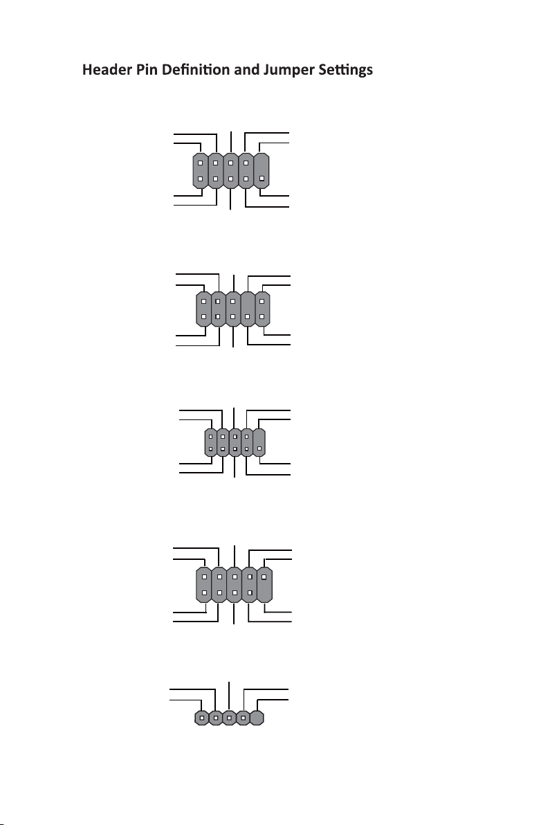
F_AUDIO
1
1
9
F_USB1
1
1
COM1~2
Key
PORT 1L
PORT 1R
PORT 2R
AUD_GND
AUD_GND
PRESENCE#
SENSE1_RETURN
Key
SENSE2_RETURN
KEY
NC
KEY
1
F_PANEL
Hard disk LED (-)
Hard disk LED (+)
Reset Switch (-)
Reset Switch (+)
Reserved
Power Switch (-)
Power Switch (+)
MSG LED (+)
MSG LED (-)
Ground
Ground
Power +5V
Power +5V
Ground
NC
USB Port B (-)
USB Port A (+)
USB Port A (+)
USB Port B (+)
USB Port A (+)
Serial Output
Data Carrier Detect
Serial Input
Ring Indicator
Data Terminal Ready Clear to Send
Request to Send
Data Set Ready
Ground
PORT 2L
F_USB2

B450AM4-M USER MANUAL
6
CPU_FAN
Sensor
PWM
System Ground
Power +12V
SYS_FAN1~2
1
Sensor
PWM
System Ground
Power +12V
1
LPT
1
INIT
Ground
SLCT
Ground
Key
Ground
Ground
AFD
ERROR
Ground
Ground
Ground
Ground
PD1
PD5
PD2
PD6
SLCT
PD4
PD3
STROBE
PD0
PD7
ACK
BUSK
PE
SPKR
1
SPK_LP
SPK_RN
SPK_RP
SPK_LN
1
IntruderGround
CASE

7
B450AM4-M USER MANUAL
CLR_CMOS
1-2: NORMAL
Before clearing the CMOS, make sure to turn off the system.
3
1
2
2-3: CLEAR CMOS
USB3F
1
Front Panel USB Power
Front Panel USB Power
Ground
Ground
USB3 ICC Port1 D+
Not Connected
Ground
Ground
USB3 ICC Port1 D-
USB3 ICC Port2 D+
USB3 ICC Port2 D-
USB3 ICC Port1 SuperSpeed Rx-
USB3 ICC Port2 SuperSpeed Rx-
USB3 ICC Port1 SuperSpeed Rx+
USB3 ICC Port2 SuperSpeed Rx+
USB3 ICC Port1 SuperSpeed Tx-
USB3 ICC Port2 SuperSpeed Tx-
USB3 ICC Port1 SuperSpeed Tx+
USB3 ICC Port2 SuperSpeed Tx+
3
1
2
Ground
Ground
Ground
Ground
PS_ON
Ground
-12V
+3.3V
+5V
+5V
+5V
-5V
+5V
Ground
+5V
Ground
+3.3V
+3.3V
PWRGD
Ground
+12V
+5VSB
+12V
+3.3V
+12VGround
+12VGround
ATX12V
1
ATX_POWER
1

B450AM4-M USER MANUAL
8
I/O Ports
1. PS/2 Mouse(green)
Use the upper PS/2 port to connect a PS/2 mouse.
2. PS/2 Keyboard(purple)
Use the lower PS/2 port to connect a PS/2 keyboard.
3. VGA Port
Connect your monitor to the VGA port.
4. DVI Port
Connect your monitor to the DVI port.
5. Display Port
You can connect the display device to the display port.
6. HDMI Port
You can connect the HDMI device to the HDMI port.
7. USB 3.1 Ports
Use the USB 3.1 ports to connect USB 3.1 devices.
8. USB 3.0 Ports
Use the USB 3.0 ports to connect USB 3.0 devices.
9. LAN Port
Connect an RJ-45 jack to the LAN port to connect your computer to the Network.
10. USB 2.0 Ports
Use the USB 2.0 ports to connect USB 2.0 devices.
11. Line-in(blue)
It can be connected to an external CD/DVD player, Tape player or other audio
devices for audio input.
12. Line-out(lime)
It is used to connect to speakers or headphones.
13. Microphone(pink)
It is used to connect to a microphone.
LAN LED Status Description
OFF No data
Orange blinking Active
OFF No link
Green Link
Activity LED
Link LED
Link LED
LAN Port

9
English
Hardware Installation Guide
Installation Steps
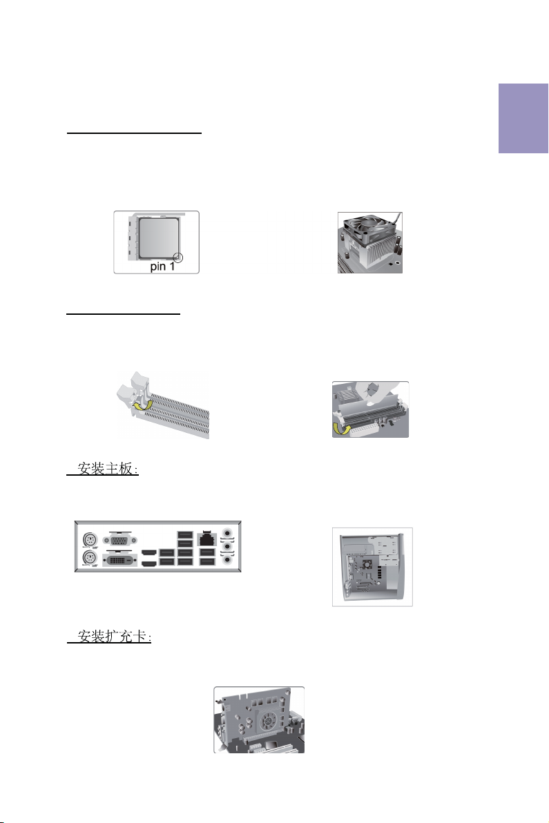
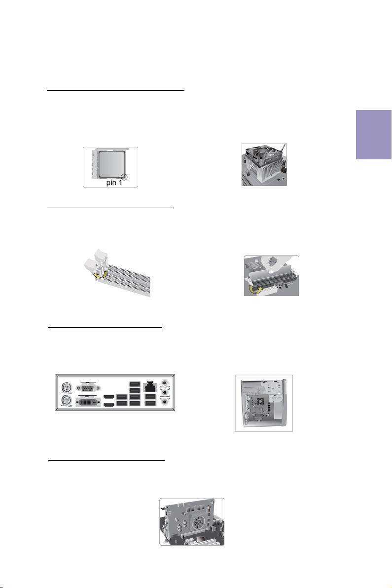
Step 2. Installation of Memory Modules:
2-1. Unfasten the latches on each side
of the DIMM slots.
Step 3. Installation of Motherboard:
3-1. Replace the back I/O plate of the
case with the I/O shield provided in
motherboard’s package.
2-2. Firmly press the DIMM down until it
seats correctly. Make sure the slot
latches are levered upwards and latch
on the edge of the DIMM.
3-2. Place the motherboard within the
case by positioning it into the I/O plate.
Secure the motherboard to the case
with screws.
Step 4. Installation of an Expansion card:
Remove the metal located on the slot and then insert the expansion card into the
slot. Press the card firmly to make sure it is fully inserted into its slot. And then
return the screw back to its position.
Step 1. Installation of the CPU and CPU Cooler:
1-1. Position lever at a 90 degree angle.
Locate the CPU cut edge (the comer
with the pin hold noticeably missing).
Align and insert the CPU correctly, then
press the metal lever back into its
original position.
1-2. Apply thermal grease on top of the
CPU. Put the CPU Fan down on the
retention module and flip the levers
over the heat sink in place.

10
English
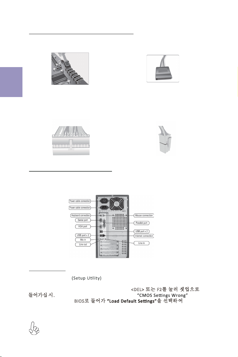
Step 5. Connecting Cables and Power Connectors:
c. Connect 24-pin power cable
The ATX_12V 4-Pin power connector is used
to provide power to the CPU. When installing
4-pin power cable, the latch of power cable
matches the ATX_12V connector perfectly.
b. Connect SATA power connector to the
SATA device
Once the steps above have been completed, please connect the peripherals such
as the keyboard, mouse, monitor, etc. Then, connect the power and turn on the
system. Please install all the required software.
Step 6: Connecting ports on the case:
a. Connect the SATA hard drive to its
SATA cable
d. Connect 4-pin power cable
Please note that when installing 24-pin
power cable, the latches of power cable
and the ATX connector match perfectly.
The sequence of installation may differ depending on the type of case and
devices used.
Using BIOS
The BIOS (Basic Input and Output System) Setup Utility displays the system’s
configuration status and provides you options to set system parameters. When
you power on the system, BIOS enters the Power-On Self Test (POST) routines,
please press <DEL> or F2 to enter setup. When powering on for the first time, the
POST screen may show a “CMOS Settings Wrong” message. Please enter BIOS and
choose “Load Default Settings” to reset the default CMOS values. (Changes to
system hardware such as different CPU, memories, etc. may also trigger this
message.)
11
1.安装CPU和CPU风扇:
硬件安装指南
安装步骤
2.安装记忆体模组:
2-1. 向外扳开内存插槽两端的卡扣。
3.
3-1. 取下机箱后面的I/O挡板,换上主
板附带的I/O弹片。
2-2. 对准内存插槽,将内存条往下按直至完
全插入。正确安装后插槽两端的卡扣会自动
锁住内存条边 缘。
3-2. 将主板的后I/O对准机箱上的I/O挡板孔
位,放入机箱并以螺丝固定。
4.
移除机箱后面的扩充金属挡板,确认扩充卡完全插入扩展 槽后,重新拧上螺丝。
简体中文
1-1. 将CPU插槽旁的固定推杆拉到垂直
状态。
将CPU上金色的三角形标示对准
CPU插槽上三角形标示,小心地将CPU
正确置入插槽,然后把固定推杆放下到
锁定位置。
1-2. 在CPU上涂好一层平滑的散热膏将 CPU
风扇固定在散热片上方。

12
5.连接电源线与电源接头:
c. 连接24针电源线与电源接头
4针电源接头提供CPU电源。其电源接头与电
源线必须完全扣合。
b. 将SATA电源接头连接至SATA设备a. 将SATA电缆连接至SATA 硬盘
d. 连接4针电源线与电源接头
请注意电源接头与电源线必须完全扣合。
简体中文
当上述安装步骤完成后,请开始安装键盘,鼠标,
源并启
显示器等外围设备,然后连接电
动系统。请安装好所需的软件。
6.连接机箱端口:
此说明内容中提供图片或安装方式仅供参考。
BIOS使用设定
BIOS程序画面会显示系统配置,同时提供操作选项让您设定系统参数。当开机时,
BIOS会进行开机自我测试 (POST),请点击<D EL> 或F2 进入BIOS程序设定。第一次
开机时,POST画面可能会显示 信息,请进入BIOS选单并选
择将BIOS重新设定为默认值 (更换CPU或内存等硬件变更也
可能会出现此信息)。
13
모듈 설치하기:
1단계. CPU와CPU
하드웨어 설치 가이드
단계별 설치 방법
2단계. 메모리
2-1. D I M M 슬롯의 각측면에 있는
걸쇠를 풉니다.
3단계. 마더보드 설치하기:
3-1. 케이스의 후면 I/O 플레이트를
마더보드의 패키지에 제공된 I / O
실드로 교체합니다.
2-2. DIMM이정확하게 설치될 때까지 단
단히 누릅니다. 슬롯 걸쇠를 위로
DIMM의 가장자리를 잠급니다..
3-2. 마더보드를 I/O 플레이트에
위치시
켜케이스 내에.
스크류로
마더보드를
케이스에 고정시킵니다.
쿨러 설치하기:
한국어
올려
4단계. 확장 카드 설치하기:
슬롯에 설치되어 있는 금속을 제거하고 확장 카드를 해당 슬롯에 삽입합니다. 슬롯에
완전히 삽입될 수있도록 카드를단단히 누릅니다. 스크류를 다시 제자리에 체결합니다.
1-1. 레버가 90도각이 되게 합니다. CPU
절단 모서리(눈에 띄게 핀고정 장치가
누락되어 있는 모서리)의위치를확인합
니다 . CPU를정확히 삽입한 후금속 레버
를눌러 원위치가 되게 합니다.
1-2. 써멀 그리스를 CPU 상단에 도포합니다
CPU 팬을 고정용 모듈에 체결한
후
레버를
채워 히트싱크를 제위치에 고정시킵니다.
.
14
5단계. 케이블 및전원 커넥터 연결하기:
c. 4핀전원 케이블을 연결합니다
ATX_12V 4핀전원 커넥터는 전원을 CPU에
공급하기 위해 사용됩니다. 4핀전원 케이블
설치시에는, 전원 케이블의 걸쇠가 ATX_12V
커넥터와 완벽하게 맞아야 합니다.
b. SATA 전원 커넥터를 SATA 장치에 연결합
니다
a. SATA 하드 드라이브를 SATA
케이블에 연결합니다
d. 4핀전원 케이블을 연결합니다
24핀전원 케이블 연결시 전원 케이블과
ATX 커넥터의 걸쇠가 완벽하게 맞아야
합니다.
한국어
일단 위의 단계들이 완료되면, 키보드, 마우스, 모니터 등과 같은 주변기기들을
연결
합니다. 그런 후에, 전원을 연결하고 시스템을 켭니다. 모든 필수 소프트웨어를 설치
합니다.
6단계. 케이스의 포트 연결하기:
BIOS 사용하기
BIOS 셋업 유틸리티 는시스템의 환경설정 상태를 표시하며 시스템
매개변수를 설정하기 위한 옵션을 제공합니다. 시스템의 전원을 켜면, BIOS는
Power-On Self Test (POST) 루틴을 실행합니다, <DEL> 또는 F2를눌러 셋업으로
들어가십 시.오 처음으로 전원을 켜면 POST 화면에 메시지가
나타날 수 있습니다. BIOS로들어가 을선택하 여 기본 CMOS
설정값을 재설정합니다. (CPU, 메모리 등과 같은 시스템 변경할 때에도 본 메뉴가
나타날 수있습니다.)
설치절차는 사용된 케이스 및장치의 유형에 따라 다를 수있습니다.
15
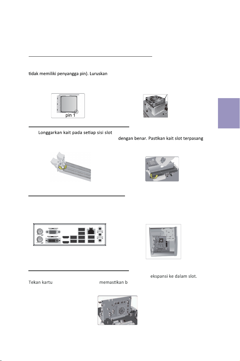
Langkah 1. Pemasangan CPU dan Pendingin CPU:
Panduan Pemasangan Perangkat Keras
Langkah-Langkah Pemasangan
Langkah 2. Pemasangan Modul Memori:
2-1.
DIMM.
Langkah 3. Pemasangan Motherboard:
3-1. Pasang kembali pelat I/O casing
dengan pelindung I/O yang disediakan
dalam paket motherboard.
2-2. Tekan kuat DIMM hingga terpasang
pada tuas atas dan kaitkan pada tepi DIMM.
3-2. Tempatkan motherboard pada casing
dengan memosisikannya ke dalam pelat I/O.
Kencangkan motherboard pada casing
dengan
sekrup.
Bahasa
Indonesia
Langkah 4. Pemasangan kartu Ekspansi:
Lepaskan logam yang terletak pada slot lalu masukkan kartu
dengan kencang untuk ahwa kartu telah masuk sepenuhnya ke
dalam slot. Lalu pasang kembali sekrup ke dalam posisinya.
1-1. Posisikan tuas pada sudut 90
derajat. Cari tepi pemisah CPU (sudut yang
dan masukkan CPU dengan benar, lalu
tekan tuas logam kembali ke posisi
awalnya.
1-2. Apply thermal grease on top of the
CPU.Oleskan gemuk termal pada bagian
atas CPU. Simpan kipas CPU pada modul
penahan dan putar tuas ke atas untuk
mengunci unit pendingin pada tempatnya.
16
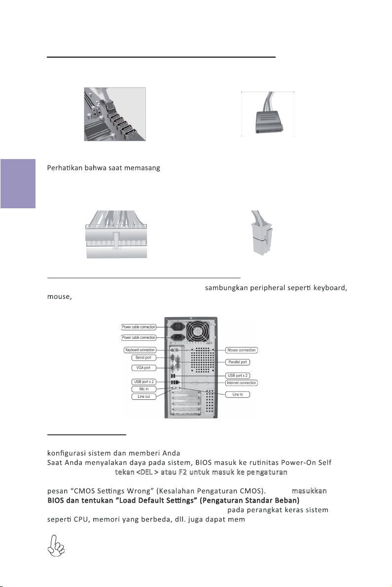
Langkah 5. Menyambungkan Kabel dan Konektor Daya:
c. Sambungkan kabel daya 24 pin
Konektor daya ATX_12V 4 pin digunakan untuk
menyediakan daya ke CPU. Saat memasang kabel
daya 4 pin, kait kabel daya cocok dengan konektor
ATX_12V.
a. Sambungkan hard drive SATA ke kabel
SATA
b. Sambungkan konektor daya SATA ke
perangkat SATA
d. Sambungkan kabel daya 4 pin
kabel daya 24, kait pada kabel daya
dan konektor ATX harus sesuai.
Bahasa
Indonesia
Setelah langkah-langkah di atas selesai, harap
monitor, dll. Lalu sambungkan daya dan nyalakan sistem. Harap pasang semua
perangkat lunak yang dibutuhkan.
Langkah 6. Menyambungkan port pada casing:
Menggunakan BIOS
Utulitas Pengaturan BIOS (Basic Input and Output System) menampilkan status
opsi untuk mengatur parameter sistem.
Test (POST), harap tekan <DEL > atau F2untuk masuk ke pe ngaturan. Saat
menyalakan untuk pertama kalinya, layar POST mungkin akan menunjukkan
untuk
icu pesan ini.)
Harap masukkan
menyetel kembali nilai CMOS standar. (Perubahan
Urutan pemasangan mungkin berbeda bergantung pada jenis casing dan
perangkat yang digunakan.

17
1-2. CPUのヒートスプレッダ(金属部)にグリスを
塗布します。CPUファンのリテンション部にCPU
ソケット両端にある爪に引っかけ、リテンション
レバーを所定の位置にします。
2-2. DIMMが正しく固定されるまでしっかり
と押します。スロットのラッチが上に持ち上が
り、DIMMの端を留めていることを確認しま
す。
3-2. I/Oプレートにマザーボードを位置決め
し、ケース内に配置します。ネジでマザーボー
ドをケースに固定します。
日本語
2-1. DIMMスロット各側のラッチを緩めます。
3-1. ケースの背面I/Oプレートをマザーボ
ードに付属のI/Oシールドと交換します。
1-1. CPUソケットの横にあるレバーを90度持ち
上げます。CPUソケットの横にあるレバーを
90度持ち上げます。 レバーを元の位置まで確
実に戻します。
フロントカバーと5.25インチのプレートをケースから取り外します。ストレージデバイス
(IDE/SATA/FDD)をケース内の位置に配置し、ネジでデバイスを固定します。

18
日本語
b. SATAハードドライブにSATAケーブル
を接続します
c. 24ピン電源ケーブルを接続します
24ピン電源ケーブルを接続するとき、電源
ケーブルのラッチとATXコネクタが適合す
ることを確認してください。
d. 4ピン/8ピン電源ケーブルを接続します
ATX_12V 4ピン/8ピン電源コネクタを
使ってCPUに電源を供給します。4ピン/
8ピン電源ケーブルを接続するとき、電源ケー
ブルのラッチとATX_12Vコネクタが適合
することを確認してください。
背面パネルは図と異なる場合があります。マザーボードによって異なります。
上記の手順を完了した後、キーボードやマウスなどの周辺機器を接続してください。その後電源
を接続し、システムを起動します。必要なソフトウェアをすべてインストールしてください。周
辺機器をすべてインストールしてください。
BIOS(基本入出力システム)セットアップユーティリティはシステムの構成状態を表示し、
システムパラメータ設定のオプションを提供します。システムを起動すると、BIOSが
POSTという診断テストのルーチンを実行します。セットアップを開始するには<DEL>ま
たはF2を押してください。初めて電源を投入したとき、POST画面に「CMOS Set-
tings Wrong」(CMOSの設定が正しくありません)というメッセージが表示され
ることがあります。BIOSに入って「Load Default Settings」(デフォ
ルトの設定を読み込み)を選択し、デフォルトのCMOS値をリセットしてください。(別の
CPU、メモリなどのシステムハードウェアへの変更でもこのメッセージが表示されることがあ
ります。)
詳細な製品仕様については仕様説明書を参照するか、ECSウェブサイトの製品マニ
ュアルで詳細な内容をダウンロードしてください。
a. IDEハードドライブにIDEケーブルを接
続します
Table of contents
Languages:
Other ECS Motherboard manuals


Popular Motherboard manuals by other brands

Gigabyte
Gigabyte MP30-AR0 Quick reference guide

Gigabyte
Gigabyte X299 AORUS Ultra Gaming user manual

LAPIS Semiconductor
LAPIS Semiconductor ML610Q304 user manual

Analog Devices
Analog Devices EVAL-ADV7612-7511 user guide

Linear Technology
Linear Technology DC1771A Demo Manual

ON Semiconductor
ON Semiconductor NIS6432 user manual


