MPS EV2759-Q-00A User manual
EV2759-Q-00A
36V SW Charger with Power Path Management
For 1-6 Cell Batteries EV Board
EV2759-Q-00A Rev.1.0 MonolithicPower.com 1
7/29/2019 MPS Proprietary Information. Patent Protected. Unauthorized Photocopy and Duplication Prohibited.
© 2019 MPS. All Rights Reserved.
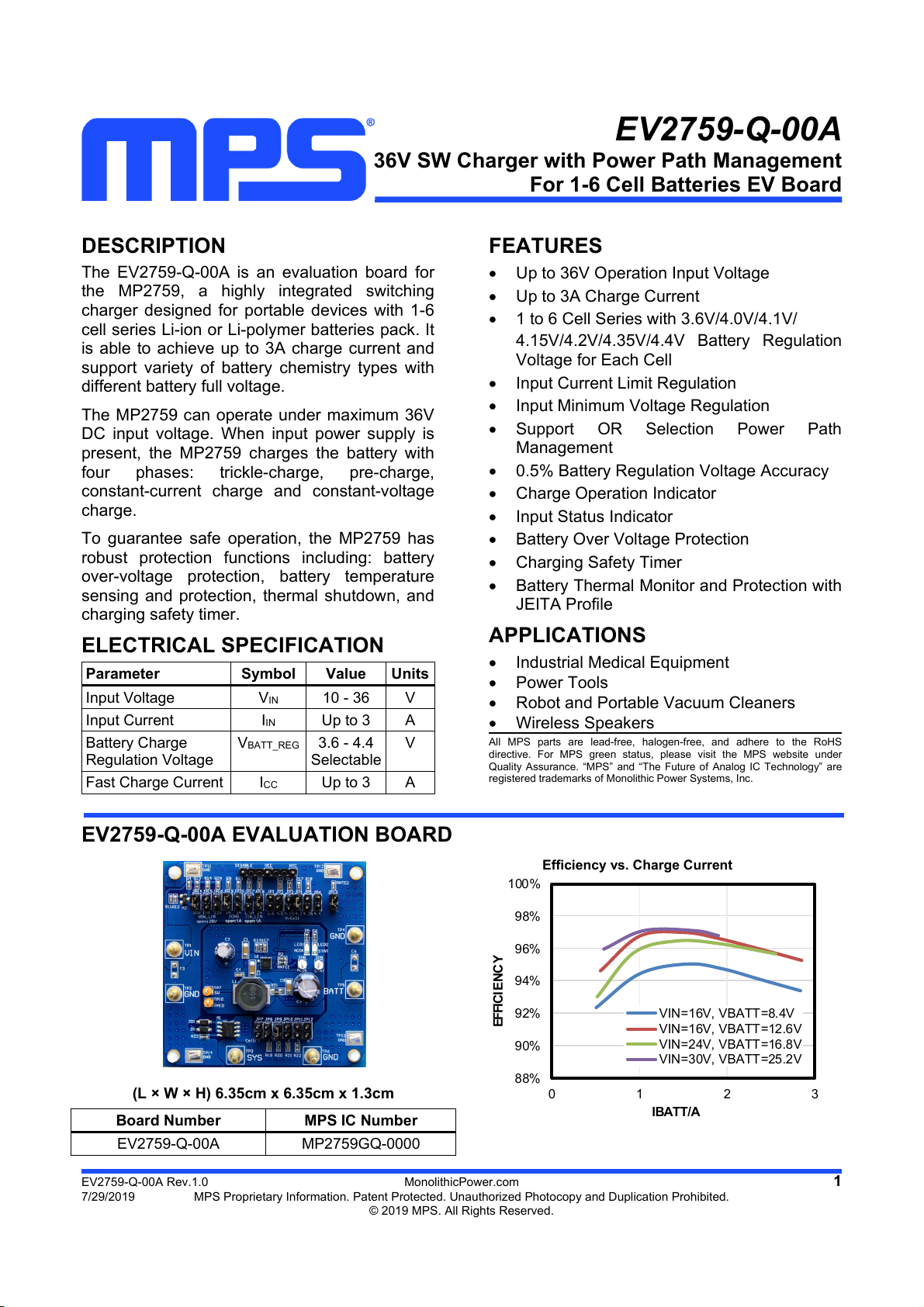
DESCRIPTION
The EV2759-Q-00A is an evaluation board for
the MP2759, a highly integrated switching
charger designed for portable devices with 1-6
cell series Li-ion or Li-polymer batteries pack. It
is able to achieve up to 3A charge current and
support variety of battery chemistry types with
different battery full voltage.
The MP2759 can operate under maximum 36V
DC input voltage. When input power supply is
present, the MP2759 charges the battery with
four phases: trickle-charge, pre-charge,
constant-current charge and constant-voltage
charge.
To guarantee safe operation, the MP2759 has
robust protection functions including: battery
over-voltage protection, battery temperature
sensing and protection, thermal shutdown, and
charging safety timer.
ELECTRICAL SPECIFICATION
Parameter Symbol Value Units
Input Voltage VIN 10 - 36 V
Input Current IIN Up to 3 A
Battery Charge
Regulation Voltage
VBATT_REG 3.6 - 4.4
Selectable
V
Fast Charge Current ICC Up to 3 A
FEATURES
Up to 36V Operation Input Voltage
Up to 3A Charge Current
1 to 6 Cell Series with 3.6V/4.0V/4.1V/
4.15V/4.2V/4.35V/4.4V Battery Regulation
Voltage for Each Cell
Input Current Limit Regulation
Input Minimum Voltage Regulation
Support OR Selection Power Path
Management
0.5% Battery Regulation Voltage Accuracy
Charge Operation Indicator
Input Status Indicator
Battery Over Voltage Protection
Charging Safety Timer
Battery Thermal Monitor and Protection with
JEITA Profile
APPLICATIONS
Industrial Medical Equipment
Power Tools
Robot and Portable Vacuum Cleaners
Wireless Speakers
A
ll MPS parts are lead-free, halogen-free, and adhere to the RoHS
directive. For MPS green status, please visit the MPS website unde
r
Quality Assurance. “MPS” and “The Future of Analog IC Technology” are
registered trademarks of Monolithic Power Systems, Inc.
EV2759-Q-00A EVALUATION BOARD
(L × W × H) 6.35cm x 6.35cm x 1.3cm
Board Number MPS IC Number
EV2759-Q-00A MP2759GQ-0000
Efficiency vs. Charge Current
88%
90%
92%
94%
96%
98%
100%
0123
EFFICI ENC Y
IBATT/A
VIN=16V, VBATT=8.4V
VIN=16V, VBATT=12.6V
VIN=24V, VBATT=16.8V
VIN=30V, VBATT=25.2V

EV2759-Q-00A 36V SW CHARGER WITH PPM FOR 1-6S BATTERIES EV BOARD
EV2759-Q-00A Rev.1.0 MonolithicPower.com 2
7/29/2019 MPS Proprietary Information. Patent Protected. Unauthorized Photocopy and Duplication Prohibited.
© 2019 MPS. All Rights Reserved.
EVALUATION BOARD SCHEMATIC
100nF
C4
VIN
BATT
10uH
L1
20K
R5
2K
R6
95.3K
R1
80.6K
R2
VCC
10K
RNTC1
GND
NTC
VB
CELL
ILIM ISET
158K
R7
ILIM
47.5K
R10
95.3K
R9
ISET
A
LL OPEN = 28
V
1.5A 2A 2A 3A
2.2uF
C5
ACOK
STAT
TP7
SW
TP8
TP9
NTC
NTC
VCC
VCC
ACOK
STAT
VLI M
PMID
TP10
NC
C3 10uF
C8
NC
C6
1uF
C1
100uF/50V
C9
GND
20m
RS1
TP11
JP2
34.8K
R15
VB
JP3
64.9K
R16
JP4
105K
R17
JP5
165K
R18
M2
2N7002
10K
R12
100
R11
DISABLE
DISABLE
DISABLE
80.6K
R8
JP1 JP6
1uF
C7
VCC
VCC
JP8
34.8K
R19
CELL
JP9
64.9K
R20
JP10
105K
R21
JP11
165K
R22
JP7 JP12
VCC
5, 6, 7, 8
1, 2, 3
M1
ZD1
1M
R23
SYS
D1
1N4148W
VIN
VIN
JP13
10K
RNTC2
LED2
LED1
TP12
TP13
TP14
GND
SW BATT
PMID
10uF
C2
10K
R3
221K
R4
110K
R13
243K
R14
JP16
22V
JP14
10V
JP15
15V
806K
R24
JP17 JP18 JP19 JP20
NTC 12
ACOK
9
CELL
10
IN
1
AGND
16
BATT 14
VB
11
SW 3
ISET
18
PGNDPGNDPGND 7
5
,6,
STAT 8
VCC
17
BST4
PM ID 2
VLI M
19
CSP 15
ILIM
13
U1
MP2759GQ
GND
GND
GND
GND
GND
GND
GND
GND
EV2759-Q-00A 36V SW CHARGER WITH PPM FOR 1-6S BATTERIES EV BOARD
EV2759-Q-00A Rev.1.0 MonolithicPower.com 3
7/29/2019 MPS Proprietary Information. Patent Protected. Unauthorized Photocopy and Duplication Prohibited.
© 2019 MPS. All Rights Reserved.
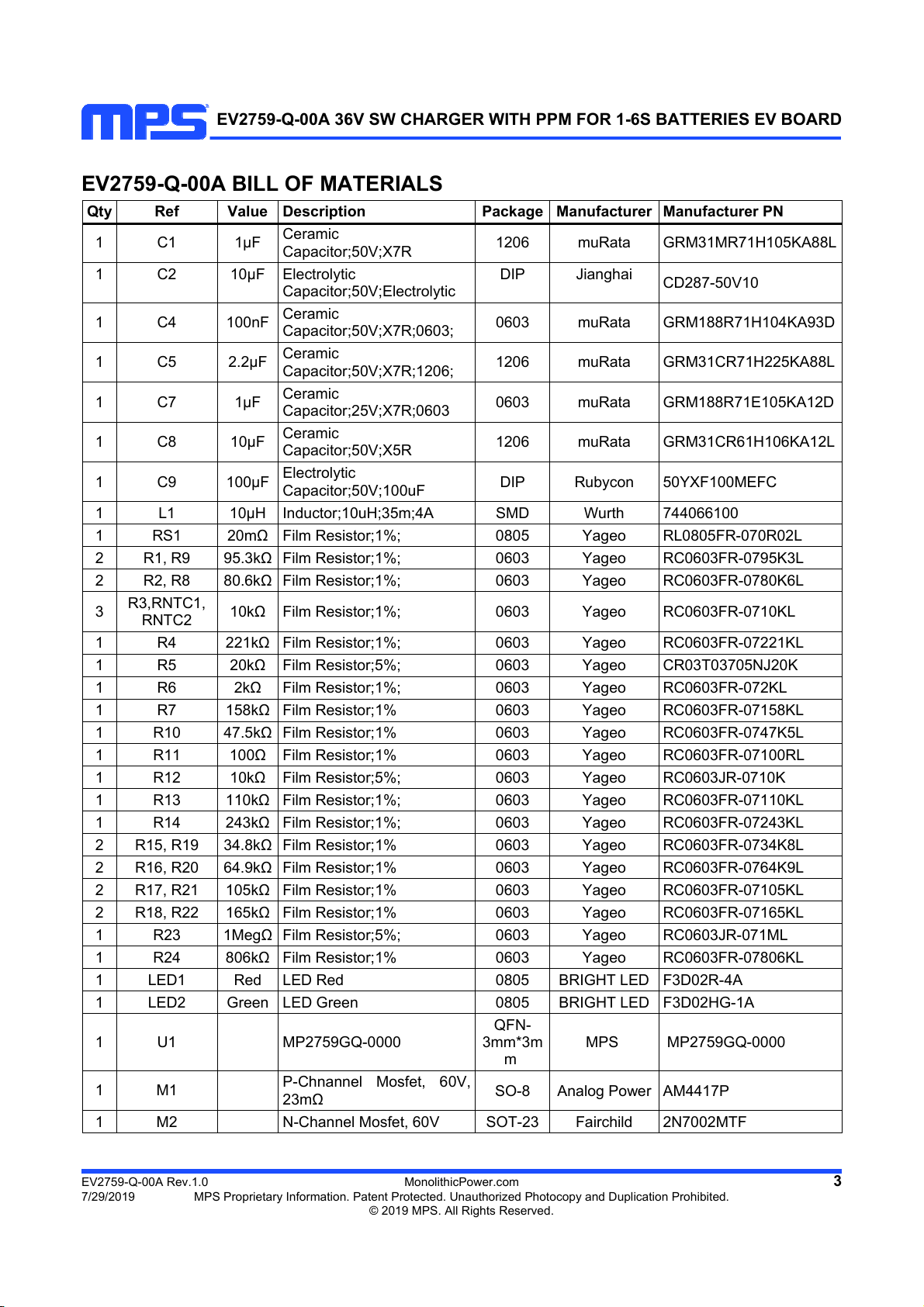
EV2759-Q-00A BILL OF MATERIALS
Qty Ref Value Description Package Manufacturer Manufacturer PN
1 C1 1µF
Ceramic
Capacitor;50V;X7R 1206 muRata GRM31MR71H105KA88L
1 C2 10µF Electrolytic
Capacitor;50V;Electrolytic
DIP Jianghai
CD287-50V10
1 C4 100nF
Ceramic
Capacitor;50V;X7R;0603; 0603 muRata GRM188R71H104KA93D
1 C5 2.2µF
Ceramic
Capacitor;50V;X7R;1206; 1206 muRata GRM31CR71H225KA88L
1 C7 1µF
Ceramic
Capacitor;25V;X7R;0603 0603 muRata GRM188R71E105KA12D
1 C8 10µF
Ceramic
Capacitor;50V;X5R 1206 muRata GRM31CR61H106KA12L
1 C9 100µF
Electrolytic
Capacitor;50V;100uF DIP Rubycon 50YXF100MEFC
1 L1 10µH Inductor;10uH;35m;4A SMD Wurth 744066100
1 RS1 20mΩFilm Resistor;1%; 0805 Yageo RL0805FR-070R02L
2 R1, R9 95.3kΩFilm Resistor;1%; 0603 Yageo RC0603FR-0795K3L
2 R2, R8 80.6kΩFilm Resistor;1%; 0603 Yageo RC0603FR-0780K6L
3 R3,RNTC1,
RNTC2 10kΩFilm Resistor;1%; 0603 Yageo RC0603FR-0710KL
1 R4 221kΩFilm Resistor;1%; 0603 Yageo RC0603FR-07221KL
1 R5 20kΩFilm Resistor;5%; 0603 Yageo CR03T03705NJ20K
1 R6 2kΩFilm Resistor;1%; 0603 Yageo RC0603FR-072KL
1 R7 158kΩFilm Resistor;1% 0603 Yageo RC0603FR-07158KL
1 R10 47.5kΩFilm Resistor;1% 0603 Yageo RC0603FR-0747K5L
1 R11 100ΩFilm Resistor;1% 0603 Yageo RC0603FR-07100RL
1 R12 10kΩFilm Resistor;5%; 0603 Yageo RC0603JR-0710K
1 R13 110kΩFilm Resistor;1%; 0603 Yageo RC0603FR-07110KL
1 R14 243kΩFilm Resistor;1%; 0603 Yageo RC0603FR-07243KL
2 R15, R19 34.8kΩFilm Resistor;1% 0603 Yageo RC0603FR-0734K8L
2 R16, R20 64.9kΩFilm Resistor;1% 0603 Yageo RC0603FR-0764K9L
2 R17, R21 105kΩFilm Resistor;1% 0603 Yageo RC0603FR-07105KL
2 R18, R22 165kΩFilm Resistor;1% 0603 Yageo RC0603FR-07165KL
1 R23 1MegΩFilm Resistor;5%; 0603 Yageo RC0603JR-071ML
1 R24 806kΩFilm Resistor;1% 0603 Yageo RC0603FR-07806KL
1 LED1 Red LED Red 0805 BRIGHT LED F3D02R-4A
1 LED2 Green LED Green 0805 BRIGHT LED F3D02HG-1A
1 U1 MP2759GQ-0000
QFN-
3mm*3m
m
MPS MP2759GQ-0000
1 M1
P-Chnannel Mosfet, 60V,
23mΩSO-8 Analog Power AM4417P
1 M2 N-Channel Mosfet, 60V SOT-23 Fairchild 2N7002MTF
EV2759-Q-00A 36V SW CHARGER WITH PPM FOR 1-6S BATTERIES EV BOARD
EV2759-Q-00A Rev.1.0 MonolithicPower.com 4
7/29/2019 MPS Proprietary Information. Patent Protected. Unauthorized Photocopy and Duplication Prohibited.
© 2019 MPS. All Rights Reserved.
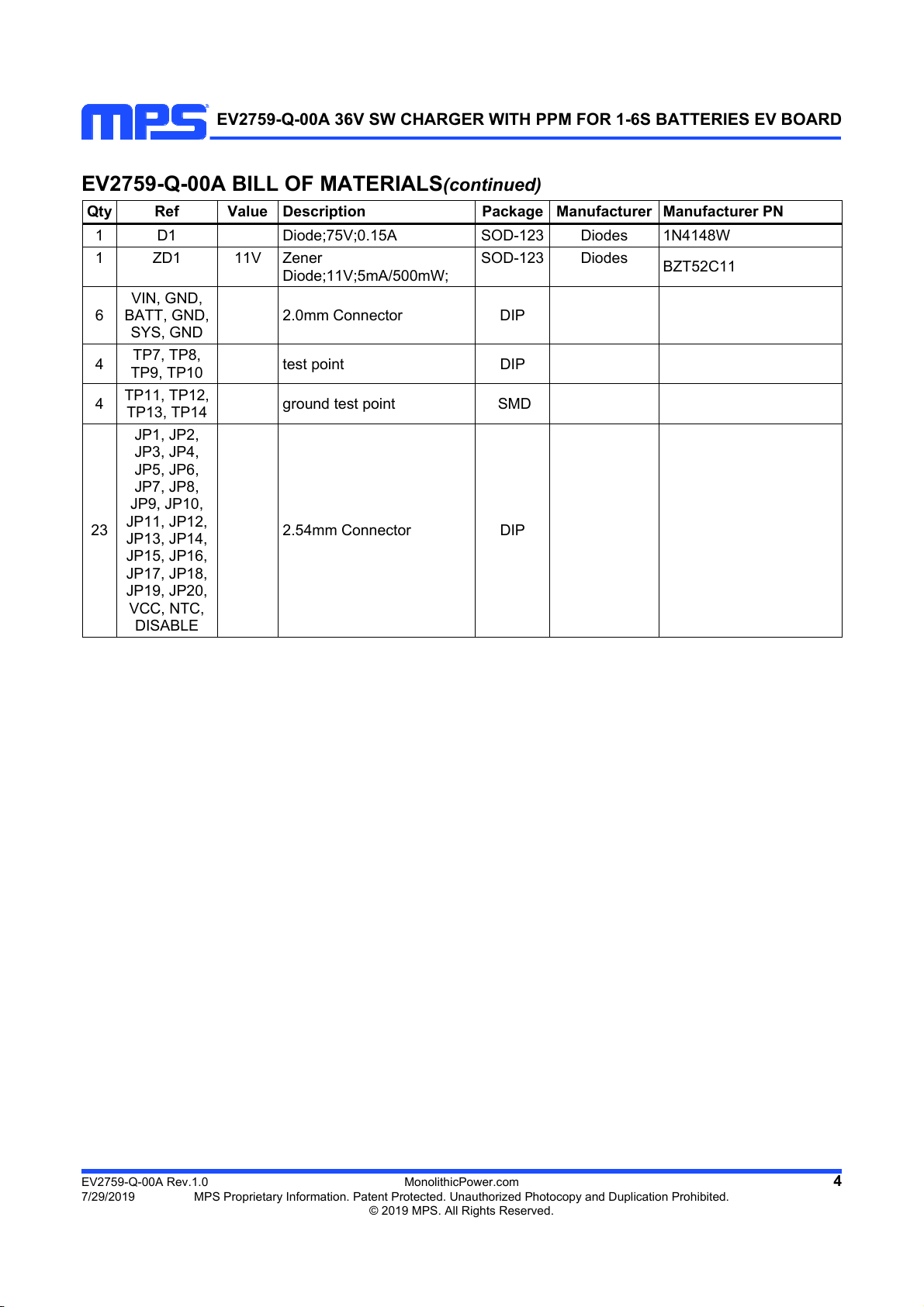
EV2759-Q-00A BILL OF MATERIALS(continued)
Qty Ref Value Description Package Manufacturer Manufacturer PN
1 D1 Diode;75V;0.15A SOD-123 Diodes 1N4148W
1 ZD1 11V Zener
Diode;11V;5mA/500mW;
SOD-123 Diodes BZT52C11
6
VIN, GND,
BATT, GND,
SYS, GND
2.0mm Connector DIP
4 TP7, TP8,
TP9, TP10 test point DIP
4 TP11, TP12,
TP13, TP14 ground test point SMD
23
JP1, JP2,
JP3, JP4,
JP5, JP6,
JP7, JP8,
JP9, JP10,
JP11, JP12,
JP13, JP14,
JP15, JP16,
JP17, JP18,
JP19, JP20,
VCC, NTC,
DISABLE
2.54mm Connector DIP

EV2759-Q-00A 36V SW CHARGER WITH PPM FOR 1-6S BATTERIES EV BOARD
EV2759-Q-00A Rev.1.0 MonolithicPower.com 5
7/29/2019 MPS Proprietary Information. Patent Protected. Unauthorized Photocopy and Duplication Prohibited.
© 2019 MPS. All Rights Reserved.
EVB TEST RESULTS
Performance curves and waveforms are tested on the evaluation board.
L = 10µH/35mΩ, CBATT=10µF, RSNS = 20mΩ, TA= 25°C, unless otherwise noted.
Battery Charge Curve
VIN=24V, 3 Cell, VBATT_REG=4.2V, ICC=3A,
IIN_LIM=2A
Trickle-Charge Steady State
VIN=24V, 4 Cell, VBATT=7V, ICC=3A, IIN_LIM=2A
CH2: VIN
CH4: IBATT
CH1: VBATT
CH3: VSW
CH2: VIN
CH1: VBATT
CH4: IL
CH3: VSW
Pre-Charge Steady State
VIN=24V, 4 Cell, VBATT=10V, ICC=3A, IIN_LIM=2A
CC-Charge Steady State
VIN=24V, 4 Cell, VBATT=12V, ICC=3A, IIN_LIM=2A
CH2: VIN
CH1: VBATT
CH4: IL
CH3: VSW
CH2: VIN
CH1: VBATT
CH4: IL
CH3: VSW
CV-Charge Steady State
VIN=24V, 4 Cell, VBATT=16.8V, ICC=3A,
IIN_LIM=2A
Power On, CC-Charge Mode
VIN=18V, 2 Cell, VBATT=8V, ICC=2A, IIN_LIM=2A
CH2: VIN
CH1: VBATT
CH4: IL
CH3: VSW
CH2: VIN
CH4: IBATT
CH1: VBATT
CH3: VSW
EV2759-Q-00A 36V SW CHARGER WITH PPM FOR 1-6S BATTERIES EV BOARD
EV2759-Q-00A Rev.1.0 MonolithicPower.com 6
7/29/2019 MPS Proprietary Information. Patent Protected. Unauthorized Photocopy and Duplication Prohibited.
© 2019 MPS. All Rights Reserved.
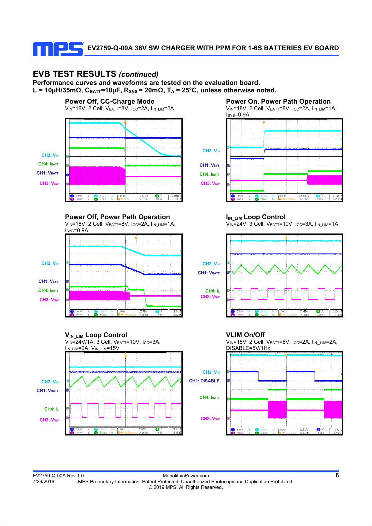
EVB TEST RESULTS (continued)
Performance curves and waveforms are tested on the evaluation board.
L = 10µH/35mΩ, CBATT=10µF, RSNS = 20mΩ, TA= 25°C, unless otherwise noted.
Power Off, CC-Charge Mode
VIN=18V, 2 Cell, VBATT=8V, ICC=2A, IIN_LIM=2A
Power On, Power Path Operation
VIN=18V, 2 Cell, VBATT=8V, ICC=2A, IIN_LIM=1A,
ISYS=0.9A
CH2: VIN
CH4: IBATT
CH1: VBATT
CH3: VSW
CH2: VIN
CH1: VSYS
CH4: IBATT
CH3: VSW
Power Off, Power Path Operation
VIN=18V, 2 Cell, VBATT=8V, ICC=2A, IIN_LIM=1A,
ISYS=0.9A
IIN_LIM Loop Control
VIN=24V, 3 Cell, VBATT=10V, ICC=3A, IIN_LIM=1A
CH2: VIN
CH1: VSYS
CH4: IBATT
CH3: VSW
CH2: VIN
CH1: VBATT
CH4: IL
CH3: VSW
VIN_LIM Loop Control
VIN=24V/1A, 3 Cell, VBATT=10V, ICC=3A,
IIN_LIM=2A, VIN_LIM=15V
VLIM On/Off
VIN=18V, 2 Cell, VBATT=8V, ICC=2A, IIN_LIM=2A,
DISABLE=5V/1Hz
CH2: VIN
CH1: VBATT
CH4: IL
CH3: VSW
CH2: VIN
CH1: DISABLE
CH4: IBATT
CH3: VSW
EV2759-Q-00A 36V SW CHARGER WITH PPM FOR 1-6S BATTERIES EV BOARD
EV2759-Q-00A Rev.1.0 MonolithicPower.com 7
7/29/2019 MPS Proprietary Information. Patent Protected. Unauthorized Photocopy and Duplication Prohibited.
© 2019 MPS. All Rights Reserved.
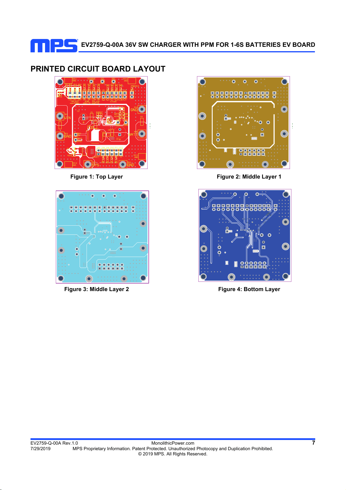
PRINTED CIRCUIT BOARD LAYOUT
Figure 1: Top Layer Figure 2: Middle Layer 1
Figure 3: Middle Layer 2 Figure 4: Bottom Layer

EV2759-Q-00A 36V SW CHARGER WITH PPM FOR 1-6S BATTERIES EV BOARD
EV2759-Q-00A Rev.1.0 MonolithicPower.com 8
7/29/2019 MPS Proprietary Information. Patent Protected. Unauthorized Photocopy and Duplication Prohibited.
© 2019 MPS. All Rights Reserved.
QUICK START GUIDE
Table 1: Connectors
Connectors Description
TP1/VIN Connect to input source positive terminal
TP2/GND Connect to input source negative terminal
TP5/BATT Connect to battery pack positive terminal
TP4/GND Connect to battery pack negative terminal
TP3/SYS Connect to system load positive terminal
TP6/GND Connect to system load negative terminal
TP7/SW Test point of switching node
TP10/PMID Test point of PMID
DISABLE, VCC, NTC,
TP8/ACOK, TP9/STAT
Test connection for related signals
TP11, TP12, TP13, TP14 /
GND
Test point of ground
Table 2: Jumpers
Jumpers Description Alternative Default
JP1,JP2,JP3,JP4,JP5,JP6 Select battery regulation
voltage for each cell
3.6V/4.0V/4.15V/4.2V/4.
35V/4.4V
4.2V
JP7,JP8,JP9,JP10,JP11,JP12 Select battery cell numbers 1cell/2cell/3cell/4cell/5c
ell/6cell
3cell
JP13 NTC divider On board NTC divider
or pull-up only
NTC divider
JP14,JP15,JP16 Select input voltage minimum
limit
10V/15V/22V/28V 10V
JP17,JP18 Select input current limit 1A/1.5A/2A 2A
JP19,JP20 Select CC-charge current 1A/2A/3A 2A
This board is designed for MP2759 which is a highly integrated switching charger for 1-6 cell Li-ion/Li-
Polymer batteries in series. And layout accommodates most commonly used capacitors.
1, Connect the battery pack to BATT and GND connectors, take care that the battery positive/negative
terminal must not be reversely connected.
2, If using a battery emulator, preset the battery emulator to proper voltage and turn off the emulator,
connect to BATT and GND, then turn on the emulator output.
3, Preset an input power source to proper voltage and turn off the power source, connect the power
source to VIN and GND, then turn on the power source. The EVB would start charging.
4, Please confirm that the NTC jumper has been connected, otherwise it would not charge because of
NTC fault.
5, To modify the charging parameters, the EVB offers multiple options to be configured by the jumpers.
The charge current can be selected among 1A/2A/3A
The input current limit can be selected among 1A/1.5A/2A
The cell numbers can be selected among 1s/2s/3s/4s/5s/6s
The battery regulation voltage of each cell can be selected among
3.6V/4.0V/4.15V/4.2V/4.35V/4.4V

EV2759-Q-00A 36V SW CHARGER WITH PPM FOR 1-6S BATTERIES EV BOARD
NOTICE: The information in this document is subject to change without notice. Please contact MPS for current specifications. Users should
warrant and guarantee that third party Intellectual Property rights are not infringed upon when integrating MPS products into any application.
MPS will not assume any legal responsibility for any said applications.
EV2759-Q-00A Rev.1.0 MonolithicPower.com 9
7/29/2019 MPS Proprietary Information. Patent Protected. Unauthorized Photocopy and Duplication Prohibited.
© 2019 MPS. All Rights Reserved.
The input voltage minimum limit can be selected among 10V/15V/22V/28V.
6, Connect the system load to SYS and GND connectors if you need, take care that the positive/
negative terminal must not be reversely connected.
7, Please take care that the max system load current should not exceed the input source capacity, if the
system load has the possibility of exceeding the input source output current limit, a schottky diode is
required to bypass Q1 body diode.
Notes
For the other detailed description on the operation of this part, please contact local FAE to
apply the latest datasheet.
Table of contents
Other MPS Motherboard manuals


MPS
MPS MP2672 User manual

MPS
MPS EVmEZDPD3603A-00A User manual

MPS
MPS MP2663 User manual

MPS
MPS EV2632-R-01A User manual

MPS
MPS EV5920-5048-V-00A User manual

MPS
MPS EVHF900-P-00A User manual

MPS
MPS EV1477-TF-00B User manual

MPS
MPS EV6539B-F-00A User manual

MPS
MPS EVBL2166-D-00A User manual

MPS
MPS EV6532-R-01A User manual


