Rittal R8 E User manual

AS 4050.454
Electrical crimping machine R8 E
Operating instructions

Contents
2 We reserve the right to make technical modifications. Rittal electrical crimping machine R8 E
EN
Contents
1About this documentation....................................................... 4
2General safety instructions...................................................... 6
2.1 Intended use.........................................................................................................6
2.2 Not permitted.......................................................................................................6
2.3 Machine dangers..................................................................................................6
2.4 Operational hazards.............................................................................................6
2.5 Hazard sources.....................................................................................................6
2.6 Safety equipment.................................................................................................6
2.7 Warning signs at and on the machine or components......................................7
2.8 Residual risks........................................................................................................7
2.9 Safety measures at the installation site .............................................................7
2.10 Notes for the operating company.......................................................................7
2.11 Personnel requirements......................................................................................8
2.11.1 Operator................................................................................................................. 8
2.11.2 Technician............................................................................................................... 8
2.12 Training and instruction.......................................................................................8
2.13 Noise.....................................................................................................................8
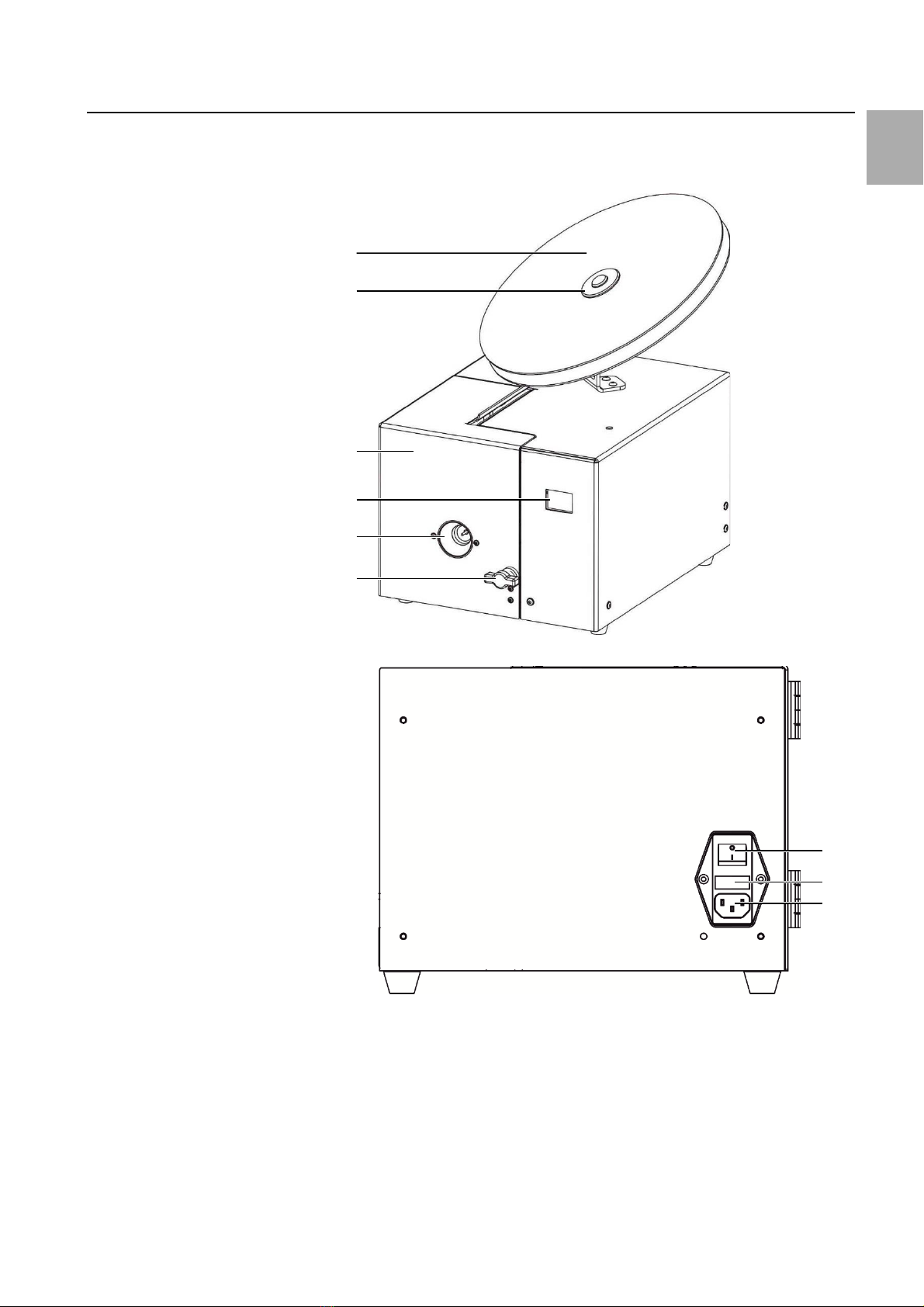
3Device description................................................................... 9
3.1 Overview...............................................................................................................9
3.2 Technical data.....................................................................................................10
4Transporting the machine ......................................................11
5Setting up the machine ..........................................................11
5.1 Operating tools...................................................................................................11
5.2 Machine connection..........................................................................................11
5.3 Inserting the belt roll.........................................................................................12
5.4 Cross-section setting..........................................................................................13
5.4.1 Die size setting...................................................................................................... 14
5.4.2 Insulation stripping stage setting........................................................................... 15
5.5 Replacing the belt roll........................................................................................15
5.6 Conductor insertion / conductor cutting..........................................................15
6Menu.....................................................................................16
6.1 Joggingoperation...............................................................................................16
6.2 Counters..............................................................................................................17
6.2.1 Reset daily quantity counter.................................................................................. 17
6.2.2 Service counter..................................................................................................... 17
6.3 Fillinglevel monitoring......................................................................................17
6.4 Test menu...........................................................................................................17
7Maintaining the machine .......................................................18
7.1 Authorised maintenance personnel.................................................................18
7.2 Maintenance notes............................................................................................18
7.3 Lubricant.............................................................................................................18
7.4 Maintenance schedule.......................................................................................19
7.4.1 Daily maintenance................................................................................................. 19
7.4.2 Monthly maintenance ........................................................................................... 19
7.4.3 6-monthly maintenance ........................................................................................ 20
7.5 Replacing the insulation stripping blade ..........................................................22
7.6 Replacing ferrule separating blade...................................................................22
8Troubleshooting.....................................................................24
8.1 Personnel for troubleshooting..........................................................................24
8.2 Machine does not start......................................................................................24
8.3 Ferrules placed too deep in the transportunit................................................25

Contents
Rittal electrical crimping machine R8 E We reserve the right to make technical modifications. 3
EN
8.4 Error messages.................................................................................................. 25
8.5 Removingthe wire end ferrule......................................................................... 26
9Machine decommissioning and disposal................................. 26
9.1 Machine decommissioning............................................................................... 26
9.2 Machine disposal............................................................................................... 26
10 Electrical connection diagram ................................................27
11 Spare parts list and accessories..............................................28

1 About this documentation
4 We reserve the right to make technical modifications. Rittal electrical crimping machine R8 E
EN
1About this documentation
The warnings in this documentationare structured differently depending on the
severity of danger.
Warning!
Possible risk of fatality!
Noticeswith the signal word "warning" warn you aboutsituations
which could leadto fatal or serious injuries if you do not pay attention
to the notices specified.
Caution!
Risk of injury!
Noticeswith the signal word "caution" warn you aboutsituations
which could leadto injury if you do notpay attentionto the notices
specified.
Caution!
Propertydamage!
Noticeswith the signal word "attention" warnyou aboutdangers whichcould
result in damage to property.
Situation-related warnings may contain the following warning symbols:
Symbol
Meaning
Warning: dangerous electrical voltage
Warning: injury to hands due to sharp blades
Work may only be performed by a qualified electrician
Only perform work with personal protective equipment
Disconnect the mains plug
Notes on documentation
Additional formattingis usedin the restof the textwhich has the following mean-
ing:
Note:
This constitutes information which is not related to safety,butwhich
provides importantinformation regarding correctand effective work.
◼This symbol indicates an "action point" and showsthatyou shouldperforman
operation or procedure.

2 General safety instructions
6 We reserve the right to make technical modifications. Rittal electrical crimping machine R8 E
EN
2General safety instructions
2.1 Intended use
The electrical crimping machine R8 E is an electrically-driven insulation stripping
and crimping machine designedexclusively forinsulation strippingfromflexible
conductors in accordancewith DIN60228:2005and the crimping of "wire end fer-
rules on rolls" (0.5 –2.5mm²) on cable ends. For this reason, becauseof its con-
struction, the machine has only this intendeduse.
For the intendeduse,the following mustbe observed:
–All notes fromthe operating instructions
–The documentation of the supplied products,as well as
–The notes for servicing/maintenance
Any other use is deemed improper.
The operationalsafety of the machineis guaranteedonly forthe intended use.
Only persons authorised by the manufacturermay performchanges, conversions
and repairs to the machine.
Any safety-relevant changes or manipulations to the machine areprohibited. If the
operating company makes suchchanges or manipulations, safe operationof the
machines is not guaranteed.
The manufacturer acceptsno liabilityfor damageor consequentialdamages that
resultbecause of the preceding measures.
Use only original spare parts and accessories authorised by the manufacturer. The
use of other parts voids the liability for any damage(also consequentialdamages)
that results from the use of other parts or non-authorisedaccessories.
2.2 Not permitted
–Removing notification or warning signs.
–Opening the machineduring operation.
–Using the machine with obvious defects or damage.
2.3 Machine dangers
A risk evaluation with subsequentsafety inspection and safetyacceptance was per-
formed on the electrical crimping machineR8 E. As for everymachine, someresid-
ual risks,that cannotbe precludedbecauseof designconsiderations, remain.See
section 2.8 "Residual risks".
2.4 Operational hazards
The operator may rectifyonly thosefaultsfor which the housing doesnotneed to
be removed.
2.5 Hazardsources
◼Before performing servicing, maintenanceand cleaning workon the machine,
switch off the machine,disconnectitfromthe power supply (e.g.cutoff the elec-
tricity supply,switch off the fuse).
2.6 Safety equipment
Safety equipment is installed to protectpersonnel. The operating company is
obliged to inspectthe safety equipment annually.
Under no circumstancesmay safety devicesbe changed, removed orcircumvented
by changes to the machine.
Safety devices
Function
Inspection
Housing
The housing may be re-
moved only by service
technicians or qualified
Inspect for damage.

2 General safety instructions
Rittal electrical crimping machine R8 E We reserve the right to make technical modifications. 7
EN
personnel. Only for
switched-off state of the
machine. After removal of
the housing, ensure that
the earthing wire is insert-
ed before the machine is
closed again.
Safety switch
The safety switch is acti-
vated when the front flap is
opened.
By a qualified electrician.
LPV-100-24 switched-mode
power supply (SMPS)
The SMPS protects against
dangerous voltages, be-
cause not more than 60
VAC or 110 VDC may be
present.
By a qualified electrician.
2.7 Warning signs at and on the machine or components
–PE conductorconnection: This marking isplaced on theearth screw.
Symbol
Meaning
The protective earth is a measure that in the event of a fault protects
against dangerous touch voltage and electrical shock. The "protective
earth" measure is provided by the protective conductor.
The connectionis made viaan IECconnector with leading protective conductor
contact.The "PE"protectiveconductor(green/yellow insulating sheathonly in
Germany) isused for these protective measures.
2.8 Residualrisks
Even when all safety and warning notes areobserved,residualrisks remain forthe
machine operation.
The machine is state-of-the-artand builtaccording to recognisedsafety regula-
tions.Nevertheless, hazards forusers or third-parties can result when operating
the machine.
–The machine maybe usedonly forthe intended purpose.
–The machine mustbe in propersafety condition during commissioning.
–Faults that can impair the safety must be rectified immediately, whereby the
manufacturermay need to be contacted.
–For openedflap, access to the fixed bladeis possible and so cut injuries can re-
sult.
–Manipulation of the safetydevicescan causethe reoccurrenceof the described
hazards.
2.9 Safety measures at theinstallationsite
The machine mustbe placed stableon atable.
–There isa large hazard risk should amachine fall.
Note:
Inner-companyinstructions and checks should ensurethat the work-
place and itsvicinity remainclean and uncluttered.
2.10 Notes for the operating company
–The operatingcompanyis obligedto write operatinginstructions.
–The operating companyis obligedto inspect the safety devices annually.

2 General safety instructions
8 We reserve the right to make technical modifications. Rittal electrical crimping machine R8 E
EN
–Deploy only original fuses with the specifiedamperage.
–Knowledgeof the local,operational safety and accident-preventionregulations.
–All notes on machinesmustbe kept legible, and renewedwhennecessary.
◼Notify the manufacturer withoutdelay shoulddefects becomeapparent,provid-
ed they were not causedintentionally.
◼Any imperfect machineparts mustbe replaced immediately.
2.11 Personnel requirements
The following target groups havedifferent authorisations.
2.11.1 Operator
Requirements:
–Literacy skills
–Technical knowledge
–Instructed/trained
Knowledge:
–Machine function
–Intended use of the machine
–Machine safety devices
2.11.2 Technician
Requirements:
–Rittal servicetechnician
Work steps
Target group
Operator
Technician
Transporting
X
X
Mounting
X
Dismantling
X
Setup
X
X
Operation
X
X
Cleaning
X
X
Maintenance
X
X
Repairs
X
2.12 Training and instruction
–Only trained and instructedpersonnelmay work on the machine.
–Repair work may be performed onlyby the manufacturer or authorisedservice
departments.
2.13 Noise
The A-weightedequivalent continuoussoundpressurelevelof the R8 Ecrimping
machine is ≤70 dB(A).
Consequently, earmuffs are not requiredfor operating the machine.

3 Device description
Rittal electrical crimping machine R8 E We reserve the right to make technical modifications. 9
EN
3Device description
3.1 Overview
Fig. 1: Front view
Fig. 2: Connection circuit-board
1
2
3
4
5
6
7
8
9

3 Device description
10 We reserve the right to make technical modifications. Rittal electrical crimping machine R8 E
EN
Key
1Belt roll
2Roll holder
3Flap
4Touch display
5Insertion funnel
6Twist lock
7ON/OFF power switch
8Fuses
9Mains plug
3.2 Technical data
Electrical crimping machine R8 E
Conductor insertion length
40 mm
Wire end ferrules
0.5 –2.5 mm²
Ferrule length
8 mm
Crimping form
Trapezoidal
Drive
Electric motor
Voltage
100…240 V
Frequency
50/60 Hz
Power consumption
100 VA
Fuse (mains filter module)
2 x T2AH250V
Degree of protection
IP 20
Protection class
I / PE conductor
Cycle time
1.8 s
Continuous sound pressure level
≤70 dB(A)
Dimensions (W x D x H)
288 mm x 349 mm x 230 mm
Weight
16 kg
Operating environment
Storage/transport temperature
-25 °C to +55 °C (short-term +70 °C)
Ambient temperature
+5 °C to 40 °C
Operating temperature
+10 °C to 45 °C
Max. operating altitude
2000 m above mean sea level
Humidity
50% at 40 °C (without dewing)
90% at 20 °C (without dewing)
Contamination level
2

4 Transportingthe machine
Rittal electrical crimping machine R8 E We reserve the right to make technical modifications. 11
EN
4Transporting the machine
Alwaysuse the complete originalpackagingfor transport.
Note:
The machine with all its accessories mustbe sentfor serviceand re-
pair work.
Caution!
Force cancause damageto the machine.
◼Transport the machine properly.
Caution!
There is arisk of injury, in particular to feet,should themachinefall.
◼Wear safety shoes whentransporting the machine.
5Setting up the machine
◼Read the operatinginstructions carefully beforecommissioningthe machine.
◼Deploy the machine onlyin a dry environment.
5.1 Operating tools
Tools
Included in the scope ofsupply
Allen key size 4
✔
Allen key size 2.5
✘
Tweezers
✘
5.2 Machine connection
Caution!
The electrical datashown on the rating plate mustmatch thatof the powergrid.
–Otherwise,damagecan occur to the machine.
◼Connect the mains cableto the mains plug(see fig.3, item 3) of the machineand
to the power supply.
◼Switch on the electrical crimpingmachine R8 E at the power switch (see fig. 3,
item1).

5 Setting up the machine
12 We reserve the right to make technical modifications. Rittal electrical crimping machine R8 E
EN
Fig. 3: Connectionplate
Key
1ON/OFF power switch
2Fuses (2 x T2AH250V)
3Mains plug
5.3 Inserting thebelt roll
◼Place the beltroll (see fig.4, item 1) so thatclockwiseunrollingis possible.
◼Open the twistlock (see fig.4, item2) and swivel theflap to the side.
The transportpin mustbe atthe bottom!
Fig. 4: Inserting thebeltroll
◼Push the wire end ferrulebeltinto the magazine until thelowermostferrule
latches.
Butnot further,becauseotherwiseamalfunction can occur.
◼Check this by applying slight tensionto the belt.
1
2
1
2
3

5 Setting up the machine
Rittal electrical crimping machine R8 E We reserve the right to make technical modifications. 13
EN
Fig. 5: Feeding inthe wire end ferrules
◼Close the flapviathe twistlock.
◼Roll up the loose wire endferrulebelt.
Fig. 6: End position
5.4 Cross-sectionsetting
Fig. 7: "Display" menu display
Key
1Die size
2Insulation stripping stage
3Conductor cross-section
4Day quantity counter
5Initial position symbol
2
1
3
5
4

5 Setting up the machine
14 We reserve the right to make technical modifications. Rittal electrical crimping machine R8 E
EN
Cross-section [mm²]
Die size
Insulation stripping stage
0.50
I
1, 2, 3
0.75
4, 5, 6
1.00
II
7, 8, 9
1.50
10, 11, 12
2.50
III
13, 14, 15
Blade replacement
I II III
99
Tab. 1: Setting values
5.4.1 Die size setting
◼Open the twistlock.
◼Swivel the flap to the side.
Caution!
There is risk of fingerinjuries by thefixedferrule separating blade.
◼Do nottouch the blade whenthe drumis turned.
◼Press the drum backwards (see fig. 8, item 1) and turn (see fig. 8, item 2) to the
desired diesize.
◼Release the drumuntilitlatches.
The current nest is displayed with the bars (see fig. 8, item 3).
◼Check by turning whetherthe drum has latched.
Fig. 8: Setting thedie size
3
2
1

5 Setting up the machine
Rittal electrical crimping machine R8 E We reserve the right to make technical modifications. 15
EN
5.4.2 Insulation stripping stage setting
Requiredtool:
–Allen key size 4
The insulation stripping stage / conductor cross-section is shown in the touch dis-
play.
◼Turning clockwiseincreasesthe cross-section.
Fig. 9: Insulation stripping stage setting
5.5 Replacing the belt roll
◼Open the twistlock.
◼Swivel the flap to the side.
◼Press the transport pin upwards completely (see fig. 10,item 1) and removethe
wire end ferrulebelt(see fig.10, item2) fromthe magazine.
Continue in accordancewith section5.3 "Insertingthe beltroll".
Fig. 10: Replacing the belt roll
5.6 Conductor insertion / conductor cutting
Note:
–The cable mustbe cutstraightand mustnothave any kinks or
bends.
–Push the cable through theinsertionfunnel into the contact.
40 mm
Correct
Incorrect
Correct
Inclined
cut
–
+
1
2

6 Menu
16 We reserve the right to make technical modifications. Rittal electrical crimping machine R8 E
EN
Incorrect
Protected
conductor
Removed
conductor
Crushed
conductor
Recessed
conductor
Tab. 2: Wire entry
6Menu
6.1 Jogging operation
Jogging operation display
"Initial position"
Jogging operation display
"Not in initial position"
Fig. 11: Jogging operation
–Machine atinitial position / switchedon.
–One of the insulation strippingstages 1 to 15 mustbe set.
◼Switch off the machine.
◼Open the flap.
◼Remove the belt.
◼Close the flap.
◼Keep the display pressed.
◼Switch on the machine (machinein joggingoperation).
The display switchesto the "Jogging operationinitialposition" display.
◼Traverse backwards (see fig. 11,item 1) or forwards (see fig. 11,item 2) in jog-
ging operation using thearrowkeys.
◼Traverse the machinemanuallyuntilthe initial position (see fig. 11, item 3) is
reachedagain.
◼Alternatively:Press the handsymbol for 3 seconds.
This causes the machine to travel automatically to the initial position.
◼Switch off the machine.
◼Insertthe beltroll.
◼Switch on the machine.
3
1
2

6 Menu
Rittal electrical crimping machine R8 E We reserve the right to make technical modifications. 17
EN
6.2 Counters
Touch display
3
x
Fig. 12: Counters
Key
1Total counter
2Day counter
3Service counter
4Menu number
5Filling level monitoring status: x = active; 0 = inactive
6.2.1 Resetdaily quantity counter
–Machine atinitial position / switchedon.
◼Press the display for 3 seconds.
◼Press the display for 5 seconds.
◼Confirmthe display briefly.
6.2.2 Servicecounter
When the quantity (200,000items) in the "Service" field is attained, "Service"
flashes when switched on nexttime.
◼Pressthe touch display onceto acknowledge thedisplay.
This indicates thatthe nextserviceis nowdueand the machine shouldbe sentto
the manufacturer.
6.3 Filling level monitoring
The filling level monitoringchecks whether the start switch has beenpressed suffi-
ciently long. This function is active as standard.
Deactivate/activatethe function
◼Setinsulation stripping stage 99.
◼Press the touch display for3 seconds.
The current status of the filling level monitoring is displayed:
X = On, O = Off.
◼Tap the touch display briefly to changethe status.
◼Press the touch display for3 seconds.
The display switchesto the "Testinputs" menu.
◼Press the touch display for3 seconds.
The display switchesto the productionmenu.
◼Setthe desiredinsulationstripping stage (seesection 5.4.2"Insulationstripping
stage setting").
6.4 Test menu
Status display of the inputs (0 or 1).
◼Setinsulation stripping stage 6.
◼Switch the machine on and off again.
◼Tap the touch display ten times quickly.
The menu is exited when the touch display ispressedfor atleast2 seconds.
1
2
3
4
5

7 Maintainingthe machine
18 We reserve the right to make technical modifications. Rittal electrical crimping machine R8 E
EN
Fig. 13: Counters
Key
1Start: Microswitch
2Drum position
3Drum position
4Drum position
5Stop: Light barrier
6Flap
7Maintaining the machine
Warning!
Electrical shock causedby working on live components!
◼Before working on the machine, itmustbe disconnected from
the power grid.
7.1 Authorised maintenancepersonnel
Maintenancework may be performedonly by specially trainedand instructed per-
sonnel.
7.2 Maintenance notes
Note:
–Never cleanthe machineinteriorwith compressed air.
–Do notuse spray oil or spray grease.
–If possible, use siliconeor PTFEoils (Teflon oil), e.g. Divinol GWA ISO
46.
–Use lubricating greases suitablefor rollerbearings and sliding sur-
faces.
–The displayand the touch screenare madeof plastic and mustnot
come into contact with hard objects.The touch-screen surfacecan
be cleanedwith a softcloth withoutany solvents.
7.3 Lubricant
Lubricatinggrease
–Recommended grease: BP EnergreasePR-EP 00
Lubricatingoil
–Recommended oil:WD-40 Classic
1
2
3
4
5
6

7 Maintainingthe machine
Rittal electrical crimping machine R8 E We reserve the right to make technical modifications. 19
EN
7.4 Maintenance schedule
7.4.1 Daily maintenance
Component
Activity
Machine
◼Empty the refuse drawer.
Emptying the refuse drawer
◼Observethe insertion position of the refusedrawer.
Fig. 14: Refuse drawer
7.4.2 Monthly maintenance
◼Open the flap.
◼Oil the support (see fig. 15,item 1) and bearing assembly (see fig. 15,item 2) of
the crimping drum.

7 Maintainingthe machine
20 We reserve the right to make technical modifications. Rittal electrical crimping machine R8 E
EN
Fig. 15: Oiling the crimping drum
7.4.3 6-monthly maintenance
◼Dismantle the housing.
◼Oil the gap between the setting wheel and the insulationstripping stage.
◼To do this,place the machineat45°.
◼Allow lubricating oil to flow into the gap (see fig.16, item 1) betweenthe setting
wheel and the cover.
Fig. 16: Oiling insulation stripping stage setting
Other manuals for R8 E
1
Table of contents
Popular Crimping Tools manuals by other brands

HRS
HRS HT601/TM21P-88P operating instructions

HARTING
HARTING 09 99 000 0119 Operation manual

molex
molex CR60622B Operating Instruction and Specifications Sheet

Emerson
Emerson klauke ESM 35CFM quick start guide

Temper
Temper Koban KCB-240 instruction manual

Tyco Electronics
Tyco Electronics 1490749-1 instruction sheet

molex
molex Avikrimp 64005-3000 manual

Ilsco
Ilsco TASKMASTER TB-6DF1000-P instruction manual

SharkBite
SharkBite 865894 Instruction guide

NovoPress
NovoPress ACO153 BT operating manual

Trick-tools
Trick-tools Roper Whitney 0585 Operation, parts & maintenance manual

molex
molex RHT-5771 Operating Instruction Sheet And Specifications