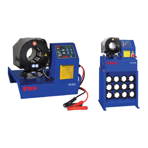
RYCO MINI CRIMPER Series User manual

OPERATION MANUAL
MINI CRIMPER SERIES
CONNECTING PARTNERSHIPS
FOR MODELS:
RY16 October 2018 | Version: v1-0


1MINI CRIMPER SERIES OPERATION MANUAL
CONTENTS
GENERAL.................................................................................................................................................................................2-6
GENERAL INFORMATION................................................................................................................................................................ 2
Warranty .......................................................................................................................................................................................2
CHECKLIST .....................................................................................................................................................................................3
Pre-Delivery Checklist ...................................................................................................................................................................3
Pre-Commencement Inspection.....................................................................................................................................................3
SAFETY RULES ............................................................................................................................................................................4-6
Danger Zones ...............................................................................................................................................................................5
Safety Notes .................................................................................................................................................................................5
Equipment.....................................................................................................................................................................................5
Battery and Oil ..............................................................................................................................................................................6
Oil Fill ...........................................................................................................................................................................................6
Running-In ....................................................................................................................................................................................6
Greasing .......................................................................................................................................................................................6
OPERATION ........................................................................................................................................... 7-12
RY16 MINI CRIMPER.......................................................................................................................................................................7
Start Up ........................................................................................................................................................................................7
Selecting the Die Sets and Setting the Crimp Diameter.................................................................................................................. 7
Crimp Range Chart .......................................................................................................................................................................8
Operating the RY16.......................................................................................................................................................................8
Crimping .......................................................................................................................................................................................8
Changing the Die Set on RY16 ...................................................................................................................................................... 8
Maintenance .................................................................................................................................................................................8
HYDRAULIC HAND PUMP ................................................................................................................................................................... 9
Operating Instruction .....................................................................................................................................................................9
Installation ....................................................................................................................................................................................9
Pump Operation .......................................................................................................................................................................... 10
Operating the Pump .................................................................................................................................................................... 10
Maintenance ............................................................................................................................................................................... 11
Hydraulic Hand Pump Troubleshooting ........................................................................................................................................ 12
SPECIFICATIONS...................................................................................................................................... 13
AIR/HYDRAULIC PUMP SPECIFICATIONS....................................................................................................................................... 13
Operation .................................................................................................................................................................................... 13
CALIBRATION ........................................................................................................................................... 14
RY16 Mini Crimper Calibration .................................................................................................................................................... 14
RY16 Mini Crimper Troubleshooting ............................................................................................................................................ 14
PREVENTATIVE MAINTENANCE.......................................................................................................... 15-17
Cleaning....................................................................................................................................................................15
Lubrication/Greasing ................................................................................................................................................................... 15
Oil Change.................................................................................................................................................................................. 15
Master Spring Change................................................................................................................................................................. 15
Spare Parts............................................................................................................................................................................ 16-17

2MINI CRIMPER SERIES OPERATION MANUAL
GENERAL INFORMATION
Do not unpack or operate the crimping machine until you have thoroughly read this manual.
All operators using the crimping machine must read this manual.
This manual provides necessary information for the safe use of this machine.
This manual is the result of continual development, testing and technical evaluations that are registered and veried according to
2006:42/EG, 2004:108/EG, 2006:95/EG, EN614-2, 97/23/EG.
The information within this manual is intended only for trained operators who can operate the machine without risk to themselves,
other persons, property, the machine, or the environment. The operator should have proven competence in
• Trouble-shooting methods
• Performing machine inspections
• Simple maintenance procedures
• Safe hose making practices and procedures, in compliance with, this manual, appropriate legislation and RYCO
Hydraulics Safe Work Instructions.
The scope of this manual does not cover disassembly or comprehensive maintenance procedures. These may only be performed
by an authorised service technician.
Store this manual and keep it in good condition for future use. Contact your nearest authorised RYCO distributor for replacement
manual or additional information if required.
RYCO is not liable for injury/damage to persons/machine or property as a result of improper use, having made prohibited
modications to the machine or misinterpreting this manual’s safety instructions.
The machine is transported on a pallet, which is easy to move and lift with a fork-lift truck. After unpacking, the machine should be
lifted using an approved, appropriately rated lifting sling.
Warranty
The warranty lasts one (1) year from purchase and only under the strict condition that the manual instructions have been followed.
The warranty covers defected material/parts and awed workmanship, replacing defected parts cost.
The warranty does not cover improper use or normal wear. Travel costs, time for repair and shipping costs are not covered by the
warranty. Repairs under the warranty are to be made only by RYCO or an authorized service technician approved by RYCO.
Lost income or extra costs that may arise for any reason are not covered by the warranty.
Please contact RYCO to discuss warranty claims.
GENERAL

3MINI CRIMPER SERIES OPERATION MANUAL
CHECKLIST
GENERAL
Pre-Delivery Checklist
Pre-Commencement Inspection
RY16
Crimper wrapped in plastic and packed in a
suitable box for Air & Sea freight
RY16 Crimper complete with
Quick Release Coupling
Tube of Grease
Technical User Manual
Grease Application Brush
Die Box
Die Sets
RY16
Included Dies
Optional Dies
Included Ordered
14mm 7mm
16mm 10mm
19mm 12mm
23mm
27mm
31mm
37mm
Before using the crimper for production, this checklist should be performed using procedures outlined herein.
Insert 9V Battery (not included) in battery holder.
Push red test button to check battery power and LED crimp light illuminates.
Check RYCO logo, safety labels and Crimp Chart decals are attached.
Check operation of Vernier Crimp dial.
Grease cone-shaped surfaces in the cylinder.
Connect Hand Pump or Air/Hyd. Foot Valve pressurise crimper to check for no oil leaks.
Check for no abnormal noise during operation across full range of motion.
Check all dies are supplied and appropriately numbered.
Check calibration as per calibration procedure.
RYCO recommend a risk assessment be performed by the end-user prior to installation and use.

4MINI CRIMPER SERIES OPERATION MANUAL
Always ensure that the minimum standards for safety, installation and operation are complied with before operating the machine.
Observe the surrounding environmental conditions such as temperature, humidity, lighting, vibrations, dust and other conditions
at the machine operation site. Never remove the machine’s information or warning plates. Contact an authorized RYCO
representative for replacement plates if they become unreadable.
The use of any spare parts not directly authorized by RYCO or any changes/modications (however insignicant) made to your
machine without authorization. Releases RYCO from any liability or warranty whatsoever.
Always dispose of operation waste in accordance with current local laws and regulations.
GENERAL
SAFETY RULES
Use only original RYCO die sets in your RYCO crimping machines. Installing and using third party die sets will be solely at
users own risk and void any warranties, and all liability on RYCO’s behalf.
Read the instructions thoroughly for secure, safe and correct operation of machines.
The equipment described in this manual is intended for professional use. It is to be operated only by a trained operator
who has demonstrated competence in the operation of the machine and hose making procedures. The machine is
designed to operate in clean, dry conditions with sufficient illumination. Openings between the die segments exceed 6
mm, the dies are deemed to be an exclusion zone as outlined in RYCO Work Instruction RH-WI-101 Safe Operation of
Crimping Machines. Refer to Figure 1 below.
The covers and guards are designed to protect the operator from injury and should not be removed.
It is recommended to use appropriate protective eyewear, gloves and safety shoes during operation and maintenance.
Figure. 1 - Crimper Zones
Pinch Point
Pinch Point
Front of Die Set
Front of Crimp Head
1/2 D
D
Rear of Die Set
30mm
Exclusion
Zone
Caution
Zone
Front View

5MINI CRIMPER SERIES OPERATION MANUAL
Danger Zones
General Warning Label
Pay particular attention to these items.
Crimping Hose Assembly Label
When crimping a hose assembly, hold the hose far enough away to avoid any pinch or crush zones.
No Hands Label
Do not put your hands in these areas while the motor is running.
SAFETY RULES
RY16
The machine consists of a chassis, crimping head and is delivered ready to use, packed in a wooden box on a pallet.
To ensure a safe and practical work environment the machines should be located in an area that provides
• Adequate working space around the machine
• Sufcient lighting of the work area.
Equipment
GENERAL
The RYCO RY16 Crimper is designed for a max input pressure of 700 bar/10,000 psi. Do not exceed this input
pressure.
Appropriate Personal Protective Equipment (PPE) must be worn during hose making and maintenance activities.
• This pump should only be used by qualied, trained persons who are familiar with this equipment.
• To avoid personal injury, keep hands and feet away from crimper and workpiece during operation.
• Do not exceed equipment ratings. Overloading causes equipment failure and possible personal injury. The crimper is
designed for a max. pressure of 700 bar (10,000 psi).
• Never Set the relief valve pressure above 725 bar (10,500 psi). Serious personal Injury could result if this maximum
limit is exceeded. Damage to crimper pump and components may also occur.
• Keep hydraulic equipment away from ames and heat. Excessive heat will soften packings and seals, resulting in
uid leaks. Heat also weakens hose materials and packaging. For optimum performance do not expose equipment to
a Temperature of 50°C (122°F) or higher. Protect hoses and cylinders from weld spatter.
Safety Notes
Hose Assembly
Should a hydraulic hose rupture, burst or need to be disconnected, immediately shut off the pump and shift the control
valve to release all pressure.
• Never grasp a leaking pressurized hose with your hands.
• Always keep the hose away from re, sharp surfaces, heavy impact and extreme heat or cold. Never kink, twist, curl
or bend the hose so tightly that the oil ow within will be blocked or reduced.
• Always inspect the hose for wear periodically, as any of these conditions can damage the hose and possibly result in
personal injury.
• Hose material and coupling seal must be compatible with the hydraulic uid used.
• Hose must not come in contact with corrosive materials.
• Never paint a coupling, hose will deteriorate due to toxic materials.
• Never use the hose to move attached crimper*. Stress can damage the hose and may cause personal injury.

6MINI CRIMPER SERIES OPERATION MANUAL
Follow procedures herein to ll the RY16-HP or
RY16-AP oil reservoir with hydraulic oil the equivalent of
RYCO Hydraulic Oil 46. It is recommended to pump the oil
into the reservoirs through a 20μ lter, to avoid transferring
impurities. If any oil spills, clean up immediately with a
RYCO Spill Kit.
Oil Fill
Battery and Oil
These items are governed by International shipping
requirements. Generally they will not have batteries
installed and will be delivered dry. Check the oil
tank and ll as required prior to use using procedure
herein.
RYCO SPILL KIT
RYCO HYDRAULIC OIL
GENERAL
SAFETY RULES
The Master Dies are greased at the point of
manufacture after nal testing. This should not be
relied on to protect the crimper during initial use.
Prior to commissioning, the machine should be
greased according to operating Instructions.
Greasing of the master dies is critical to ensuring a
long and trouble-free life for the crimper.
Greasing frequency should be increased when
operating in aggressive or high volume environments.
Friction
Pressure Heat
Impurity
Time
Volume
Recommended Greasing Time
Greasing
Running-In
Recommended run-in period for a new machine is 2 crimps.
It is recommended the greasing process is carried out at least
twice a day, more if the machine is in constant use.
The purpose of frequent greasing is to ensure that there is
always enough grease between the sliding surfaces. Due to
the surface pressure the grease sinks in to the metal pores
ensuring good sliding properties for the machine’s lifetime.
During the run-in period grease the machine after every
100 crimps.

7MINI CRIMPER SERIES OPERATION MANUAL
Selecting the Die Sets and Setting the Crimp Diameters
Each machine has a table attached that indicates the crimping range for every die set.
Crimping diameter is controlled and set by the vernier dial control in Figure 2 & 3.
Turn the vernier dial so that the zero (0) on the dial is lined-up with the zero (0)
on the scale.
If zero (0) is set, the machine will crimp the smallest diameter shown in the table
for that die set.
Every revolution of the dial increases the value on the scale one unit.
One turn clockwise corresponds to 1mm on the crimping measurement.
The measurement is added to the smallest diameter the die set is capable
of reaching.
Example: A 16 mm nished crimp dimension requires die set size 16 with the
vernier dial set to zero (0) and lined up with zero (0) in the window.
A 22.2 mm nished crimp dimension requires die set size 19 with the vernier dial
turned 3 (three) clockwise rotations until 3 (three) on the scale and the 2 (two)
on the dial is lined up with the zero (0) line on the scale.
The set crimping measurement values can differ slightly from the actual
crimping measurement because the machine’s die expansion and retraction.
Compensate this by adjusting the setting.
Refer to Figure 3 for information.
Figure 3: Vernier Scale
RY16 MINI CRIMPER
OPERATION
Machine Placement
Place the machine and pump on a stable and at surface
with adequate work space, and away from any hazards.
Selecting Dies
Determine the crimping dimensions for the hose assembly
and select the die set with the correct range that
corresponds with the required nished crimp diameter.
Selecting the die set within the correct range will achieve
the best crimping results. Every die is marked with the
smallest crimping measurement in the range.
Note!
Crimping outside the range is not recommended. Using
dies that are too small risks the ferrule becoming oval and
the hose assembly not performing as expected.
Start Up
Test Light
Vernier Crimp Settings
Figure 2: RY16 Mini Crimper
Scale
Control
knob

8MINI CRIMPER SERIES OPERATION MANUAL
0
0 turn 1 turn 2 turn 3 turn 4 turn 5 turn 6 turn 7 turn
16-10 10 11 12
16-12 12 13 14
16-14 14 15 16
16-16 16 17 18 19
16-19 19 20 21 22 23
16-23 23 24 25 26 27
16-27 27 28 29 30 31
16-31 31 32 33 34 35 36 37
16-37 37 38 39 40 41 42 43 44
USE NEXT SIZE
DIE SET
8
6
4
2
7
5
3
1
0
0
8
6
4
2
7
5
3
0
8
6
4
7
5
3
0
2
1
8
6
4
7
5
3
8
6
7
5
0
4
8
6
7
0
8
7
0
5
6
8
0
7
RY16 MINI CRIMPER
1. Select relevant die set and install into crimper.
2. Ensure that all dies are correctly installed in the crimper
3. Press red test button to ensure LED crimp light illuminates.
4. When the die set is inserted in the machine and the crimping measurement set, place the hose and coupling
assembly between the dies.
NOTE: For clearance and performance reasons, RYCO recommends crimping be performed with the
coupling positioned with its termination/connecting end protruding out of the front of the crimper.
5. Pressurise the RYCO hand pump (see page 10 for detailed pump instructions) or activate the air/hydraulic foot
valve to commence crimping the coupling.
6. The crimping diameter is reached when the red LED crimp light is illuminated.
7. Remove the hose assembly from the crimper after depressurising the hand pump or hydraulic foot pump (see
page 10 for detailed pump instructions).
8. Ensure that the crimp dimension is correct and make adjustments if necessary.
Operating the RY16
Changing the Die Set on RY16
1. Retract the crimper completely by depressing the hand pump or foot valve.
2. Isolate the airline from the foot valve to ensure the crimper cannot be activated.
3. Remove each crimp die segment by turning it in either direction or pulling it towards the centre of the crimper.
4. Ensure crimper master dies surfaces are clean and free of any debris.
5. Ensure that the die set to be installed are clean, undamaged and that all are marked with the same number.
6. With the die marking numbers facing the front of the crimper, insert each die so that the die pin engages with the
mating die pin hole in the crimper master die.
7. Ensure that all dies are correctly inserted in the machine.
Maintenance
The machine should be cleaned and lubricated every eight (8) operation hours. Retract the dies to lubricate. Use a
small brush to lubricate the cone shaped surfaces in the cylinder. Lubricate sparingly and often. Without lubrication, the
machine loses power and you will damage the sliding surfaces.
Refer to preventative maintenance section for maintenance requirements.
OPERATION
CRIMPING RANGE DIE LENGTH
Die Set mm inch mm inch
RY16-07 7-10 0.276-0.394 60 2.36
RY16-10 10-12 0.394-0.472 60 2.36
RY16-12 12-14 0.472-0.551 60 2.36
RY16-14 14-16 0.551-0.630 60 2.36
RY16-16 16-19 0.630-0.748 60 2.36
RY16-19 19-23 0.748-0.905 60 2.36
RY16-23 23-27 0.905-1.062 60 2.36
RY16-27 27-31 1.062-1.220 60 2.36
RY16-31 31-37 1.220-1.457 60 2.36
RY16-37 37-44 1.457-1.772 60 2.36
Figure 4: Die Size and Crimp Range Chart
Crimp Range Chart

9MINI CRIMPER SERIES OPERATION MANUAL
OPERATION
HYDRAULIC HAND PUMP
These instructions must be read thoroughly.
Operating Instructions
Hydraulic Hand Pump Specification
Pump
Model Max. Pressure Rating Oil Volume
Per Stroke Usable Oil
Capacity
Weight
With Oil
Max.
Handle
Force
1st Stage 2nd Stage 1st Stage 2nd Stage
bar psi bar psi bar psi bar psi mL oz kg lb kg.f lb.f
RY16-HP 20 290 700 10,000 19.4 281 2.8 406 750 25.4 7.8 17.2 35 77.2
Connecting The Pump
1. Remove shipping plugs from pump outlet ports.
2. Connect hoses to pump. To seal threads, use thread
sealing paste or thread sealing tape. See Figure 5.
When using sealing tape, apply tape one thread back from the end of tting to
prevent tape from entering the hydraulic system.
3. Install a pressure gauge in-line from the pump for added safety and better control (optional).
4. Connect the hose assembly to your crimper.
Venting
This RY16-HP hand pump is designed for non-vented operation.
The oil ll plug can be loosened if needed to vent air from the system but should be
closed before using the pump.
Air Bleeding
Removing air from the hydraulic system will help the crimper to close and retract smoothly.
RY16-HP
1. Loosen or remove the oil ll plug to perform the following air bleeding procedures
2. Completely close the release valve by hand.
3. Position the pump in a horizontal position at higher level than the RY16 Crimper.
4. Operate pump to close the crimper completely.
5. Open release valve to retract the crimper. This will force any trapped air to move up
into the pump reservoir.
6. Repeat steps 2 through 5 as needed, until the crimper closes and retracts smoothly.
7. Add oil if necessary and ret oil ll plug.
IMPORTANT: To prevent contaminants from entering the hydraulic system,
do not operate pump with oil ll plug loosened or removed.
Installation
Figure 5: Thread sealing tape
Thread sealing tape.
Table 1: RY16-HP Hand Pump Specication

10 MINI CRIMPER SERIES OPERATION MANUAL
OPERATION
HYDRAULIC HAND PUMP
Before Using the Pump
1. Inspect all system ttings and connections to be sure they are tight and leak free.
2. Check oil level in reservoir and add oil if needed. Refer to instruction in
maintenance section.
3. Read and understand the following precautions before operating pumps:
BE CAREFUL: In certain situations the pump handle can “spring back”.
Always keep your body to the side of the pump, away from the line of force of the handle.
BE CAREFUL: Keep hands and ngers away from pinch point area between pump
handle and lifting handle, when operating the pump handle.
CAUTION: Never add extensions to pump handle. Extensions cause unstable pump operation.
CAUTION: To prevent mechanical damage, do not pull on pump handle after it has reached the end of its travel. Do
not apply side force to pump handle.
BE CAREFUL: At the stage of high pressure, take short strokes to reduce handle force.
Maximum leverage is obtained in the last 5 degrees of stroke.
Pump Operation
Two Stage Flow
Under no loading, the pump operates in the high ow stage for fast advance. When the load is contacted, the pump shifts
automatically to the low ow stage to build up pressure. After the pump shifts, priming takes less force.
Note: For the best performance, priming pump handle at moderate speed during the high ow stage. Fast handle speed in the high
ow stage will prevent the pump from delivering full volume of oil.
The RY16-HP is designed for use with single-acting cylinders (Crimper) and is equipped with an integral release valve.
1. Close the release valve by hand by turning dial clockwise until it stops.
2. Open the release valve by hand by turning dial counter-clockwise to release the pressure and allow oil to ow back to the
reservoir.
CAUTION: If release valve dial is difcult to turn or becomes stuck, discontinue using pump immediately.
Have pump inspected and repaired by RYCO authorised dealers.
Operating The Pump
Pump Position
The pump may be used in either the horizontal or vertical position. When operated in the vertical position, hose end of pump must
be pointing down, or the pump will pick up air and will not build up pressure properly.

11MINI CRIMPER SERIES OPERATION MANUAL
OPERATION
HYDRAULIC HAND PUMP
Removing air from the hydraulic system will help the crimper to close
and retract smoothly.
Adding Oil to the Pump
IMPORTANT: Always add oil with crimper fully retracted or the system will
contain more oil than the reservoir capacity.
Check oil level regularly and add oil if needed. Refer to the follows.
1. Place pump in the horizontal position on a level surface.
2. Remove oil ll plug from reservoir.
3. Check oil level. See Figure 6. If oil level is low, add additional oil until
oil level reaches the bottom thread of the oil ll plug opening.
IMPORTANT: Do not overfill!
Some air space must be present in reservoir to allow proper operation.
If the reservoir contains too much oil, a vacuum will form, prevent oil ow when pump is operated.
4. Ret the oil ll plug after the oil is added. Be sure the plug is fully tightened (not loose).
5. Remove air from system if necessary as per the air bleeding section and recheck oil level.
Maintenance
Figure 6: Oil Level
Lubrication
To extend pump life and improve performance, lubricate the three handle pins
regularly using a suitable lubricating oil. Refer to Figure 7.
Figure 7: Lubricating Points

12 MINI CRIMPER SERIES OPERATION MANUAL
TROUBLESHOOTING
HYDRAULIC HAND PUMP
Problem Possible Cause Solution
Crimper does not close or
closes slowly.
1. System components leaking Check all connection are fully tightened.
2. Lower fluid level in Reservoir Add oil.
3. Air tapped into system Refer to Air Bleeding section on page 9 -10 .
4. Too much fluid in Reservoir Remove excess oil.
5. Release valve not fully closed Close the release valve completely by hand.
Crimper closes, but not
holding pressure.
1. System components leaking Check all connection are fully tightened.
2. Fluid leading past inlet or outlet checks Contact RYCO Hydraulics for service.
3. Seals worn or leaking Contact RYCO Hydraulics for service.
Pump handle has a
"spongy" feel 1. Air trapped in system Refer to Air Bleeding section on page 9-10.
A system failure may or may not be the result of a pump malfunction. Determining the cause of the problem is the key objective.
Troubleshooting

13MINI CRIMPER SERIES OPERATION MANUAL
SPECIFICATIONS
AIR/HYDRAULIC PUMP
The RY16-AP Air/Hydraulic pumps are designed
for operation of RY16 Crimpers up to a max.
permissible working pressure of 700 bar (10,000
psi). The air operated hydraulic pump is a pressure
intensier which converts air pressure from 5 to
12 bar (75-170 psi) to a maximum proportional
hydraulic pressure of 700 bar (10,000 psi).
Stationary pneumatic system, compressors or air
bottles can be used for powering the pump.
Attention: Make absolutely sure that the air input pressure for the pump does not exceed 12 bar (170 psi).
If necessary, use a pressure regulator.
For producing the maximum oil output pressure an air input pressure of 8.5 bar (120 psi) is required. The oil pressure is limited in
any case to 700 bar (10,000 psi) by an adjustable pressure relief valve regardless of the air input pressure.
Attention: Due to the risk of personal injury or damage to pump and crimper do not adjust the pressure relief valve to more than
700 bar (10,000 psi). The pump is operated by a foot pedal on top of the oil reservior.
Operation
1. Make the pneumatic and hydraulic connection.
Push the foot pedal to position "Pump" - the crimper closes.
2. For an eventual interruption of the "advance" movement release the foot pedal. The air supply is interrupted, the pump
doesn't deliver oil anymore and the crimper dies stays in its current position.
3. For retracting the crimper dies push the foot pedal to position "Release". The oil return line is opened and the dies returns
by spring return.
Air/Hydraulic Pump Specification
Table 2: RY16-AP Air Pump Specication
Pump
Model
Max. Pressure Rating
Oil Flow at
7 bar/100 psi
Air Pressure Usable Oil
Capacity
Weight
With
Oil
Air
Consumption
Air Pressure Rated Pressure 0
bar
0
psi
700
bar
10,000
psi
bar psi bar psi ml in3kg lb m3CFM
RY16-AP 7-10 100-147 700 10,000 700 mL/min 43 in3/min 100 mL/min 6 in3/min 750 46 6.1 16.5 15 9

14 MINI CRIMPER SERIES OPERATION MANUAL
CALIBRATION
AIR/HYDRAULIC PUMP
RY16 Mini Crimper Calibration
The Crimper Vernier Dial has been factory set. If calibration is required, use the following procedure in conjunction with Figure 8.
1. Slightly close the master dies.
2. Set the dial to -0.2 position.
3. Remove the Vernier protective cover plate (where tted).
4. Loosen the lock nut (1).
5. Turn the adjusting sleeve (2) to the left until it come off the micro switch.
6. Turn the adjusting sleeve (2) to the right until the crimp LED light is activated.
7. Tighten the lock nut (1) without rotating the adjusting sleeve (2).
8. Calibration is completed. Perform a crimp cycle with the dial in the 0.0 position and measure the crimped diameter.
9. If the crimped diameter is smaller than required size, rotate the adjusting sleeve (2) to the right towards the micro switch.
10. If the crimped diameter is larger than required size, rotate the adjusting sleeve (2) to the left away from the micro switch.
11. After the correct crimp diameter is achieved re-tighten the lock nut (1) without rotating the adjusting sleeve (2).
12. Replace the Vernier protective cover plate (where tted).
Micro Switch
Problem Possible Cause Solution
Pump does not work,
crimper can't close
1. Low Air Pressure Check air line pressure.
2. Blocked Air Passage Check bore of air piston for contamination and
lubrication.
Pump works, crimper can't
be closed
1. Low Oil Level Check oil.
2. Air in Oil Line Press down switch valve (air) and push the foot
pedal to position "Release" at the same time.
Pump works, unloaded
crimper dies opens too
slowly
1. Blocked Oil Return Line Check hose assembly for kinks.
2. Dry Crimper Cones Grease crimper cones.
Pump works, crimper
closed, but the pump
doesn't produce the
max. pressure.
1. Low Air Pressure Check air pressure: 8.5 bar / 120 psi is necessary
to get the max. operating pressure.
2. Oil Leaks Check for oil leaks.
A system failure may or may not be the result of a pump malfunction. Determining the cause of the problem is the key objective.
RY16-AP Troubleshooting
Figure 8: Vernier Dial Calibration

15MINI CRIMPER SERIES OPERATION MANUAL
The machine should be cleaned and lubricated every eight (8) operation hours. Retract the dies to lubricate. Use a small brush
to lubricate the cone shaped surfaces in the cylinder. Better to lubricate sparingly and more often than seldom and excessively.
Without lubrication, the machine looses power and you will damage the sliding surfaces.
• Lubricate the inner surface of the conical anges—minimum daily with the RYCO recommended grease.
• Apply the grease at the front and rear of the dies with a small brush.
• Lubricate often with a small amount of grease rather than seldom with a lot of grease.
Lubrication/Greasing
• Change hydraulic oil after the rst 500 hours of operation and every 1,000 hours or once a year thereafter.
• Recommended oil: RYCO Hydraulic Oil 46 or equivalent.
• Handle the waste oil according to your local By laws.
• It is recommended to pump the oil into the RY16-HP/RY16-AP reservoirs through a 20μ lter, because new oil in drums is not pure.
Oil Change
Master die springs are wearing parts and therefore have to be replaced after every 100,000 crimps. To replace the springs special
tools and experience is needed. In order to get the master die springs replaced contact your RYCO representative.
Master Spring Change
Warning: Do not use the machine if there are broken or twisted springs in the machine.
Broken or twisted springs can damage the machine or cause personal injuries.
PREVENTIVE MAINTENANCE
HOW TO MAINTAIN YOUR CRIMPER
Cleaning
Keep the machine clean and free from dirt particles. A clean machine ensures a smooth and safe operation.
Wipe the machine with a dry cloth or with soft paper. Do not use water, solvents or abrasives.
The inner side of the crimping head can be cleaned with a small brush.
The following maintenance operations can be performed by the operator according to the instructions below.
However, repairs like changing seals or pump repairs must only be carried out by qualied persons.
Open the dies to the maximum retraction before servicing.
Never use compressed air to clean the crimping head.

16 MINI CRIMPER SERIES OPERATION MANUAL
PREVENTIVE MAINTENANCE
SPARE PARTS
NO RYCO PART NUMBER NAME QTY
1 RY16-HP HAND PUMP 700BAR/10000PSI RY16 1
2 On Request BASE 1
3 On Request BASE FEET 4
4 On Request FLAT BAR 1
5 On Request ROD 1
6 On Request WASHER 2
7 On Request HANDLE 1
8 On Request NUT 1
9 On Request SCREW 1
10 RY16-LED RY16 CRIMP LED LIGHT 1
11 RY16LPB RY16 CRIMP LIGHT PUSH BUTTON 2
12 RY16BATCOM BATTERY COMPARTMENT 1
13 ON REQUEST NIPPLE 1
14 R10006F 06 NPTM FEMALE QRC 10,000PSI 1
15 RY16HA HOSE ASSY 700BAR/10000PSI RY16 1
16 RY16VSB RY16 VERNIER SHROUD / BRACKET 1
17 ON REQUEST STICKER "MIND YOUR HANDS" 1
18 ON REQUEST STICKER”CRIMPING DIAM. CHART” 1
19 RY16VERNIER VERNIER POTENTIOMETER RY16 1

17MINI CRIMPER SERIES OPERATION MANUAL
PREVENTIVE MAINTENANCE
SPARE PARTS
NO RYCO PART NUMBER NAME QTY
1 On Request CYLINDER 1
2 On Request PISTON 1
3 On Request FRONT FLANGE 4
4 RY16-MDSET MASTER DIE SET SUIT RY16 1
5 RY16-RSK RETURN SPRING KIT (PK10) RY16 1
6 On Request SCREW 20
7, 8, 9, 10 RY16-SK SEAL KIT SUIT RY16 1
11 RY16-MDSK MASTER DIE SPRING (PK16) RY16 1
12 On Request MAGNET 16
NO RYCO PART NUMBER NAME QTY
1 RY16-VERNIER VERNIER POTENTIOMETER RY16 1

*Specications correct at time of printing | All Rights Reserved | Printed in Australia | Copyright: September 2018 | Released: February 2021 | Version 1-0
RYCO 24•7 SERVICE CENTRESRYCO LOCATIONS
MALAYSIA LATIN AMERICA SOUTH AFRICA EUROPE
PENANG
Plot 207 Kuala Ketil Ind. Estate Kuala Ketil,
Kedah, 09300
LIMA, PERU
Av. La Encalada 569 Of. 201-A
C.C. Monterrico Surco
Lima 33
JOHANNESBURG
340 Roan Crescent
Corporate Park North
Randjespark, Midrand
1685
AUSTRIA
2721 Bad Fischau
Windbachgasse 10
Tel: +60 4 415 2500
Email: Sales@RYCO.com.sg
Tel: +51 1 435 8323
Email: Ventas@RYCO.com.pe
Tel: +27 10 4100 500
Email: Sales@RYCO.co.za
Tel: +43 676 723 95 37
Email: [email protected]
NEW ZEALAND
+64 800 842 872
Sales@RYCOnz.co.nz
NEW ZEALAND HEAD OFFICE
AUCKLAND
4 Autumn Place
Penrose, Auckland 1061
RYCO 24•7 0800•111•24•7 Sales@RYCO247.co.nz
NORTH ISLAND
Gisborne
Hamilton
Hastings
Kaikohe
Manawatu
Masterton
Matamata
Morrinsville
New Plymouth
Opoutama
Otorohanga
Palmerston North
Pukekohe
Putaruru
Taupo
Tauranga
Waipawa
Wellesford
Wellington
Whakatane
Whangarei
Whitianga
SOUTH ISLAND
Christchurch
Blenheim
Bluff
Dovedale
Dunedin
Golden Bay
Gore
Invercargill
Nelson
Thornbury
Timaru
Westport
Winton
AUSTRALIA
+61 1300 111 247
Sales@RYCO.com.au
GLOBAL HEAD OFFICE
MELBOURNE
99 Calarco Drive,
Derrimut, VIC 3026
REGIONAL LOCATIONS
ADELAIDE
BL Shipway & Co
217 Richmond Road
Richmond, SA 5033
BRISBANE
97 Northlink Place
Northgate, QLD 4013
BLACKWATER
6 Jarrah Street
Blackwater, QLD 4717
NEWCASTLE
14 Ironbark Close
Warabrook, NSW 2304
PERTH
47 Tacoma Circuit
Canning Vale, WA 6155
RYCO 24•7 133•24•7 Sales@RYCO247.com
NSW
Bellingen
Dubbo
Gunnedah
Ingleburn
Mascot
Newcastle
Penrith
Sydney
Smeaton Grange
Wallerawang
Wetherill Park
QLD
Archerfield
Blackwater
Brisbane
Capricornia
Clermont
Dysart
Emerald
Moranbah
Narangba
Rocklea
Rolleston
SA & NT
Adelaide
Cowell
Darwin
Kadina
Kapunda
Loxton
Port Pirie
Richmond
Riverland
Roxby Downs
Whyalla
VIC & TAS
Bendigo
Melbourne
Mildura
Shepperton
Warrnambool
Devonport
Launceston
WA
Kalgoorlie
Mandurah
Newman
Perth
Port Hedland
Wangara
USA & CANADA
+1 866 821 7926
Sales@RYCO.us
HEAD OFFICE USA & CANADA
TEXAS
1616 Greens Road
Houston, Texas 77032
REGIONAL LOCATIONS
CALIFORNIA
1150 Valencia Avenue
Tustin, California 92780
ONTARIO
32 Airpark Place
Guelph, ONT
Canada N1L 1B2
IOWA
1007 West 10th Street
Pella, Iowa 50219
CHINA
DALIAN: +86 411 8886 0006
SHANGHAI: +86 512 3306 6181
Sales@RYCO.cn
DALIAN
38 Yingri Road
Ying Cheng Zi Industrial Zone
Gan Jing Zi District
Dalian 116036
SHANGHAI
2nd Building, 88 Dalian East Road
Taicang Economy Developing Area
Taicang, Jiangsu Province 215400
RYCO 24•7 1 844•700•0247 Sales@RYCO247.us
BOSSIER CITY
3210 Shed Road
Bossier City
LA 71111
Tel +1 318 747 7926
HAMMOND
6718 Kennedy Av
Hammond
IN 46323
Tel +1 219 844 6570
MICHIGAN CITY
1306 West
Highway 20
Michigan City
IN 46360
Tel +1 219 844 6570
This manual suits for next models
11
Table of contents
Other RYCO Crimping Tools manuals
Popular Crimping Tools manuals by other brands

Tyco Electronics
Tyco Electronics 90035-3 instruction sheet

TE Connectivity
TE Connectivity ERGOCRIMP 1-1579001-3 instruction sheet

Tyco Electronics
Tyco Electronics CERTI-CRIMP 90418-1 instruction sheet

Bollhoff
Bollhoff RIVCLINCH 0201 FS user manual

Panduit
Panduit Blackfin CT-2980/TO instruction manual

Emerson
Emerson Klauke EK 120UNVCFM manual

Tyco Electronics
Tyco Electronics 1490749-1 instruction sheet

TE Connectivity
TE Connectivity PRO-CRIMPER III instruction sheet

JAE
JAE 3502-MX80-2 Operation manual

West Mountain Radio
West Mountain Radio RIGrunner manual

Danfoss
Danfoss ET4200 Operator's manual

TE Connectivity
TE Connectivity 575937 instruction sheet