RIUKOE ML-BSW280 User manual

280W 10R
ML-BSW280 BSW MOVING HEAD
User Manual
KEEP THIS MANUAL FOR FUTURE NEED

2
INDEX
STATEMENT 3
ACCESSORIES 3
SAFETY INSTRUCTION 4
GENERAL GUIDELINES 4
INSTALLATION 6
TECHNICAL SPECIFICATION 8
PHOTOMETRIC DIAGRAMS 11
CONTROL SYSTEM 15
PANEL OPERATION 16
1. BRIEF 16
2. OPERATION 17
1. OPERATE LIGHT WITH TOUCH OR ENCODER BUTTON 17
2. PARAMETER VALUE SETTING 17
3. BOOLEAN PARAMETER SETTING 18
4. SUB MENU(PARAMETER)18
3. OPERATION AND PARAMETER INSTRUCTION 19
1. SET DMX ADDRESS 19
2. SET LIGHT WORK MODE 20
3. SET DISPLAY 21
4. TEST LIGHT 22
5. SET LIGHT RUN PARAMETER 23
6. VIEW STATUS 23
CHANNEL DESCRIPTION: 24

3
CLEANING AND MAINTENANCE 31
STATEMENT
Thank you for choosing RIUKOE, 10R BSW Moving Head. The product has
well capability and intact packing when leave factory. All of the
user should comply with warning item and manual, any misuse cause of the
damages are not included in our guarantee, and also cannot be
responsible for any malfunction & problem owing to ignore the manual.
ACCESSORIES
These items are packed together with the product:
Name
Quantity
Unit
Remark
USER MANUAL
1
PCS
DMX CABLE
1
PCS
OMEGA
2
PCS

4
SAFETY INSTRUCTION
Please keep this User Guide for future consultation. If you sell the unit to
another user, be sure that they also receive this instruction booklet.
GENERAL GUIDELINES
NEVER OPEN THIS FIXTURE WHILE IN USE!

5
During the initial operation of this fixture, a light smoke or smell may emit
from the interior of the fixture. This is a normal process and is caused by
excess paint in the interior of the casing burning off from the heat
associated with the lamp and will decrease gradually over time.
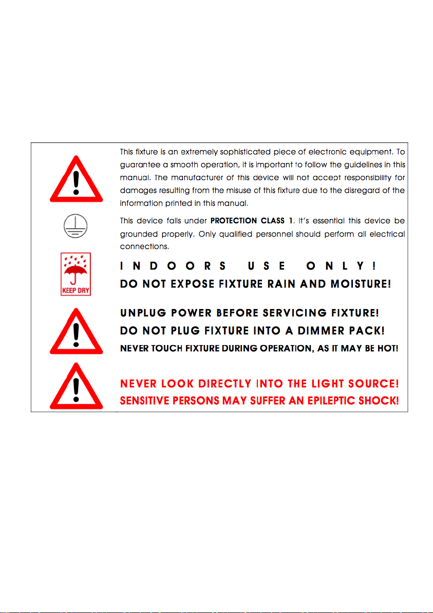
This fixture is a professional lighting effect designed for INDOOR / DRY
LOCATIONS ONLY on stage, in nightclubs, theatres, etc.
Please make sure there are NO FLAMMABLE MATERIALS close to the
fixture while operating, to prevent any fire hazard.
The fixture must be installed in a location with adequate ventilation, at
least 1.5 feet (.5m) from adjacent surfaces. Be sure no air ventilation slots
are blocked.
DO NOT attempt installation and/or operation without knowledge how to
do so.
DO NOT permit operation by persons who are not qualified to operate this
type of fixture. Most damages are the result of operations by
nonprofessionals. Consistent operational breaks may ensure the fixture
will function properly for many years to come.
DO NOT shake fixture, avoid brute force when installing and/or operating
fixture.
Always install the fixture with an appropriate safety cable. When installing
the fixture in a suspended environment, always use mounting hardware
that is no less than M10 x 25 mm, also be sure the hardware is insert in
the pre-arranged screw holes in the bracket of the fixture.
Use the original packaging and materials to transport the fixture in for
service.
DO NOT TOUCH the housing bare-hand during its operation. Turn OFF
the power and allow approximately 15 minutes for the fixture to cool down
before replacing or serving.

6
INSTALLATION
C A U T I O N S
For added protection, mount the fixture in areas outside walking paths,
seating areas, or in areas were unauthorized personnel might reach the
fixture.
Ambient operating temperature range for this fixture is 5° to 113°F. (-15°
to 45°C) Do not use the fixture under or above this temperature.
Before mounting the fixture to any surface, make sure the installation
area can hold a minimum point load of 10 times the weight of the fixture.
Fixture installation must always be secured with a secondary safety
attachment, such as an appropriate safety cable.
Never stand directly below the device when mounting, removing or
servicing.
The unit should be mounted via its screw holes on the bracket. Always ensure
that the unit is firmly fixed to avoid vibration and slipping while operating. And
make sure that the structure to which you are attaching the unit is secure and is
able to support a weight of 10 times of the unit’s weight. Also always use a
safety cable that can hold 12 times of the weight of the unit when installing the
fixture.

7
The equipment must be fixed by professionals. And it must be fixed at a place
where is out of the touch of people.
Clamp mounting
The moving head provides a unique mounting bracket assembly that integrates
the bottom of the base, the included ‘Omega Bracket’ and the Safety Cable
rigging point in one unit (see the illustration below).When mounting this fixture
to truss be sure to sere to secure an appropriately rated clamp to the included
Omega Bracket using a M10 screw fitted through the center hole of the
‘omega bracket’. As an added safety measure be sure to attached at least one
properly rated Safety Cable to the fixture using one of the safety cable rigging
point integrated in the base assembly.
DMX-512 control connection:
Connect the provided XLR cable to the female 3-pin XLR output of your controller and the
other side to the male 3-pin XLR input of the moving head. You can chain multiple Moving
head together through serial linking. The cable needed should be two core, screened cable
with XLR input and output connectors. Please refer to the diagram below.

8
DMX-512 connection with DMX terminator:
For installations where the DMX cable has to run a long distance or is in an electrically noisy
environment, such as in a discotheque, it is recommended to use a DMX terminator. This
helps in preventing corruption of the digital control signal by electrical noise. The DMX
terminator is simply an XLR plug with a 120 resistor connected between pins 2 and 3,which
is then plugged into the output XLR socket of the last fixture in the chain. Please see
illustrations below.
TECHNICAL SPECIFICATION
Light Sources: 280W(10R)
Live Fsue:T5 A/250
Neutral Fuse: T5 A/250
Power Voltage: AC 100-240V, 50/60Hz

9
Max Power Consumption:470W at 230V(I=2.05A,Power factor 0.96)
Typical Power Consumption : 230W at 230V(I=1.8A, Power factor 0.95)
Allow for a deviation of +/-10%
Lamp:
Lamp : YODN 280W
Base Fap2.5
Lamp life : 2000hrs (Stand mode)
3000hrs (Eco mode)
Optical System:
High luminous-efficiency glass reflector
Beam angel : 5°- 20°(spot application)
2.5°- 10°(beam application)
Color Wheel:
one color wheel, 14 kinds of color chips in one color wheel
Static Gob Wheel:
10 metal gobos & 4 beam reducers
Rotation Gob Wheel:
9 Glass gobos can be indexed and rotated in both directions at different
speeds
Gobo wheels continuous rotation
Glass gobos: outside diameter=15.9mm, image diameter=12.5mm,
thickness=1.1mm
Prisms:
Rotation 6-facet linear prism with continuous rotation in both directions
Rotation 16-facet circular prism with continuous rotation in both directions
Frost filter :

10
Separate, variable frost filter
Zoom:
Linear motorized zoom
Strobe:
Strobe effect with variable speed (max.15 flashes/sec)
Control
Graphic touch screen for fixture setting and addressing
Gravitation sensor for auto screen positioning
Battery backup of the touch screen
Readout fixture and lamp usage, receiving DMX values, temperatures. Etc
Built-in analyzer for easy fault finding, error messages
Remotely switching on/off the lamp
Built-in demo sequences
Black-out while head moving, color or gobo changing.
Self-resettable thermos-fuse
DMX Channel: 16/24 Channel
Control Modes: DMX
Pan/Tilt
Pan/Tilt: 540°/ 270°
Pan/Tilt Resolution: 16 bit, Electric correction
Movement control: tracking and vector
Pan/Tilt-lock mechanism
Temperatures:
Maximum ambient temperature : 45°
Maximum surface temperature : 90°
Minimum Distances:
Min distance from flammable surface :1m

11
Min distance to lit objects (Stand Mode-280W):10m
Min distance to lit objects (Eco Mode-230W):7.5m
Total Heat Dissipation:
1600 BTU/h (calculated)
469 Wh (calculated)
Please Note: Specifications and improvements in the design of this unit and this manual are subject to
change without any prior written notice.
PHOTOMETRIC DIAGRAMS
All diagrams are for full power of the lamp (Standard Mode)

12

13

14

15
CONTROL SYSTEM
Th
e
D
M
X512
is
w
id
ely
used
in intellig
ent
ligh
ti
ng
con
tr
ol, with a DMX 512
controller. Connect several lights together dmx in and dmx out,
3
pin
XLR
connectors
:
Pin
1:
G
ND
,
Pin
2:
Nega
tive
s
ign
a
l
(-),
Pin
3:
P
o
s
itive
s
i
gna
l
(+)

16
Panel operation
1. Brief
The light panel diagram show as Figure 1, Left area is TFT Displayer, support
touch, and right area is encoder button, both of touch and coder button can
operate light and setting.
Display & operation just like ‘Android operation system’, touch the item will set
or modify setting.
Note: Prevent damage the touch or TFT displayer, Can not use sharp objects
chick displayer.

17
Figure 1Panel diagram
2. Operation
1. Operate light with touch or encoder button
⚫The left area is TFT Displayer and touch, chick item or value with finger
will to complete operation of set light setting(parameters) or view light
state.
⚫The area on the right hand side is rotary encoder with button, As auxiliary
input interface, if disable touch function,, the encoder can been choose
to set or view the item, and then press the encoder button to confirm the
selection, rotary encoder again set the parameter value, finally, Press
encoder button one again to save value or setting.
2. Parameter value setting
When the selected item is value need to been modified, the dialog shown in
Figure 2 will popup.

18
Figure 2Dialog of value setting
⚫Modify value:Can quickly modify value via pull the slider to the desired
position, or click the button of ‘up’ or ‘down’ whit finger on the right side to
set the exact desired value, another way is roll encoder on the right hand
side of panel.
⚫Apply value:When Value had been modified, Then press the bottom of
‘apply’ in the left corner to apply to the light, but hav’t saved;
⚫Save Value:Any time, click on the lower right corner of the "OK" button,
the setting will been saved into internal memory.
3. Boolean parameter setting
⚫when the selected parameters is a Boolean value (such as ON or OFF),
can directly modify setting by chick corresponding item, the setting will
been saved right now.
⚫When the parameter is a key item, chick corresponding item, a dialog
shown in Figure 3 will been popup ask for the confirm. Chick ‘sure’ to
confirm.
Figure 3Dialog of confirm
4. Sub Menu(Parameter)
Chick item of main menu, enter corresponding sub menu, shown in Figure 4,
total 6 sub menu, includes class of parameter and status:

19
⚫ADDRESS:Set light DMX address.
⚫WORKMOD:Set light work mode, master or slave mode when in auto run
mode.
⚫DISPLAY:Set display parameter, eg. select language.
⚫TEST:Used for test light, modify DMX channel data to test function,the
corresponding function of reference channel function table.
⚫ADVANCE:Set light running parameter.
⚫STATUS:view light current status.
Figure 4Parameter menu
3. Operation and parameter instruction
Via following operation, enter sub menu(parameter menu) shown in Figure 4
⚫In main menu, chick 1/6 function button into corresponding parameter
menu.
⚫In sub menu(page), chick main item on the left side of displayer, can shift
to corresponding sub menu(page) quickly.
1. Set DMX Address
Click and select the "ADDR", can enter the page of DMX address setting,
range from 1 to 512, the address code shouldn’t is not greater than (512-
channels quantity), otherwise the light will not been controlled. Following is the

20
operation:
Enter the page of DMX address, as shown in Figure 5, click the blank area in
right side of display will pop-up diglog as in Fig. 4, modify value, then click
‘ENTER’ to confirm and save DMX address code.
Figure 5page of DMX Address
2. Set Light work mode
Enter the page of ‘WORK MOD’ as shown in Figure 6 and modify setting. Can
set light work mode, control lamp and DMX channel mode..
Light includes 3 work mode: DMX MODE, AUTO RUN and SOUND MODE,
Parameter definition as following:
⚫DMX Mode:Under this mode, the light receive data from the DMX
controller and move.
⚫AUTO RUN:Under this mode, light will run with inside code(data), ignore
data from DMX controller.
⚫SOUND Ctrl:Under this mode, light ignore data from DMX controller.,
When there is a strong sound in stage, the light will run a scene, otherwise
it will keep the last scene.
⚫M/S Choose:’M/S Choose’ is available when light just in ‘AUTO RUN’ or
‘SOUND Ctrl’ mode. If this item is set as ‘OFF’, the light don’t send data to
other light via DMX Cable. When ‘ON’, the data will send to other slave
light immediately.
⚫Lamp control:Turn on lamp when this item is set ‘ON’, otherwise, turn off
lamp. The gap between operation is limited to 30 second.
Table of contents
Other RIUKOE Dj Equipment manuals