3
Table of Contents
Table of ContentsTable of Contents
Table of Contents
1.
1. 1.
1. FEATURES
FEATURESFEATURES
FEATURES
................................
................................................................
................................................................
................................................................
.............................................
..........................
.............
4
44
4
2.
2.2.
2.
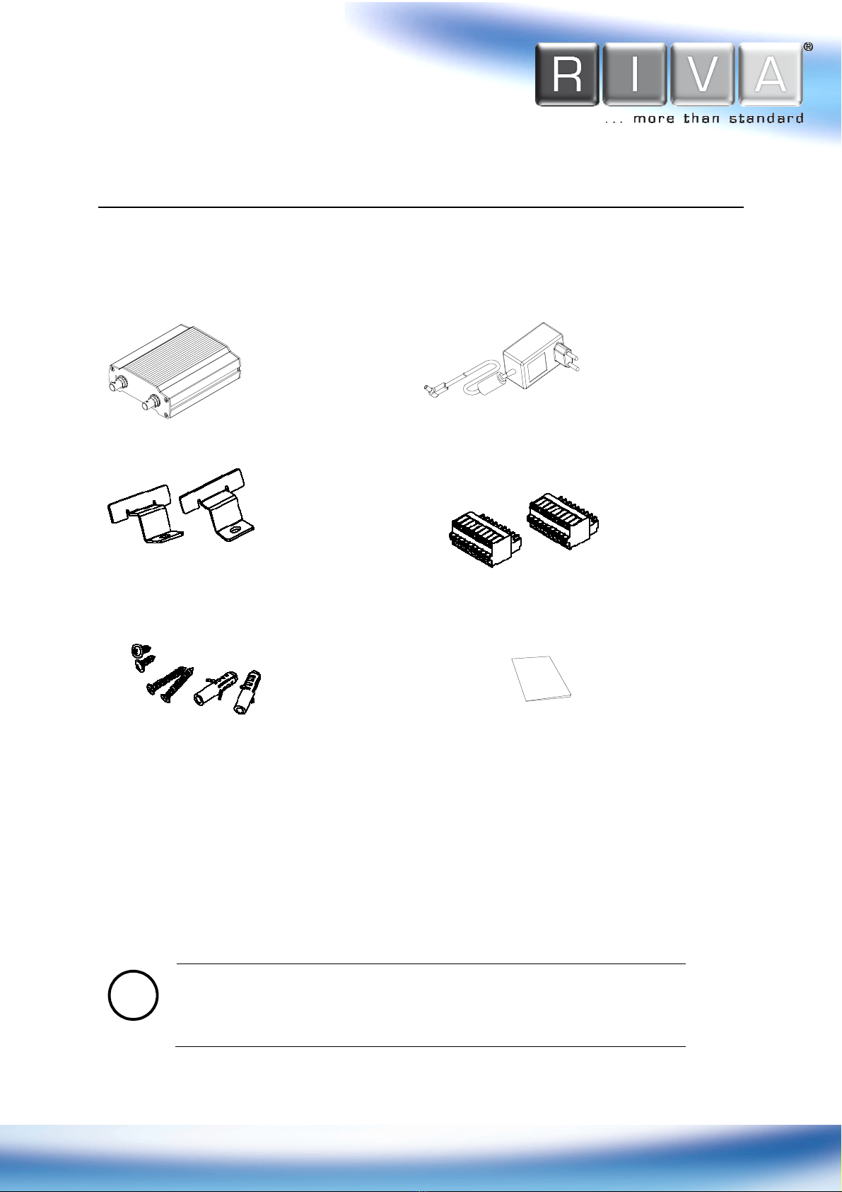
PACKAGE CONTENTS
PACKAGE CONTENTSPACKAGE CONTENTS
PACKAGE CONTENTS
................................
................................................................
...............................................................
..............................................................
...............................
5
55
5
3.
3.3.
3.
PART
PARTPART
PART
NAMES
NAMESNAMES
NAMES
................................
................................................................
................................................................
................................................................
.........................................
..................
.........
6
66
6
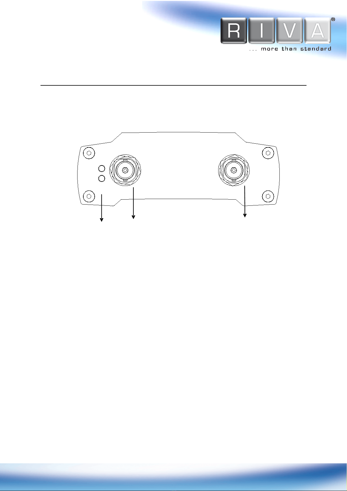
3.1. Front Panel ................................................................................... 6
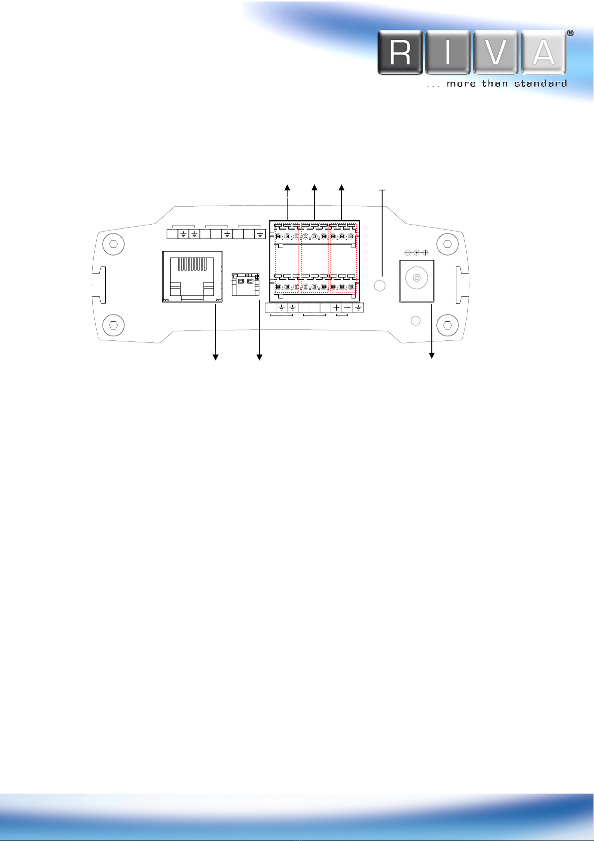
3.2. Back Panel ................................................................................... 7
4.
4.4.
4.
CONNECTIONS
CONNECTIONSCONNECTIONS
CONNECTIONS
................................
................................................................
................................................................
................................................................
........................................
................
........
9
99
9
4.1.Connectors .................................................................................... 9
5.
5.5.
5.
CONFIGURAT
CONFIGURATCONFIGURAT
CONFIGURATION
IONION
ION
................................
................................................................
................................................................
................................................................
...................................
......
...
12
1212
12
5.1. Set up network environment .......................................................... 12
5.2. View video on web page ................................................................ 12
5.2.1. View video using IPAdmin Tool .................................................. 12
5.2.2. View video using IP address ..................................................... 14
5.3. Reset ........................................................................................ 15
5.4. Factory efault ............................................................................ 15
6.
6.6.
6.
WALL
WALLWALL
WALL-
--
-MOUNTING
MOUNTINGMOUNTING
MOUNTING
................................
................................................................
................................................................
................................................................
.................................
..
.
16
1616
16
APPEN IX (A): SPECIFICATIONS
APPEN IX (A): SPECIFICATIONSAPPEN IX (A): SPECIFICATIONS
APPEN IX (A): SPECIFICATIONS
................................
................................................................
...................................................
......................................
...................
17
1717
17
Summary .......................................................................................... 17
Electrical Characteristics ...................................................................... 17
Environment Condition ......................................................................... 18
APPEN IX (
APPEN IX (APPEN IX (
APPEN IX (C
CC
C): IMENSIONS
): IMENSIONS): IMENSIONS
): IMENSIONS
................................
................................................................
........................................................
................................................
........................
18
1818
18
APPEN IX (
APPEN IX (APPEN IX (
APPEN IX (
): H
): H): H
): HEXA ECIMAL
EXA ECIMALEXA ECIMAL
EXA ECIMAL-
--
-
ECIMAL
ECIMALECIMAL
ECIMAL
C
CC
CONVERSION
ONVERSIONONVERSION
ONVERSION
T
TT
TABLE
ABLEABLE
ABLE
............
........................
............
19
1919
19
REVISION HISTORY
REVISION HISTORYREVISION HISTORY
REVISION HISTORY
................................
................................................................
................................................................
................................................................
....................................
........
....
20
2020
20