Rivco GL18007-30 User manual

2012 & NEWER GL1800 TRAILER HITCH INSTALLATION INSTRUCTIONS
#GL18007-30
Read through these instructions completely before attempting installation, and lay out all pieces
including the numbered hardware bags to familiarize yourself with all parts - see photo #1.
1. Place the motorcycle on its centerstand; remove the seat (four 6mm Allen screws securing the grab handles to
the seat), painted side covers (this will require opening the saddlebag lids), and gray plastic frame covers
surrounding the rear crash bars and passenger floorboards (three 5mm Allen screws on each). Remove the rear
fender by first removing the four 5mm Allen screws as shown in photo (2A).
2. Remove the rear crash bars and lower sub-frames (photos 3 A & B) mounting bolts. Next - drill out the
threads of the sub-frame mounting bolt hole on the right side ONLY (photo 3B) using a 5/16” drill. (This is
required due to the limited space between the hitch and rear suspension.) The new bolt supplied for this hole is
longer and will now screw into the threaded hole on the right side of the hitch’s frame.
3. Install the right frame reinforcement plate (item 1F). Referring to photo (#3), start two of the M8 x 25mm
bolts from bag #1 into the upper holes -just a few threads, do not tighten. Install the left frame reinforcement
plate (photo 1G) using the two remaining M8 x 25mm bolts from bag #1 in the upper holes - again start just a
few threads, do not tighten. Install the longer of the two remaining bolts from bag #1 (M8 x 50mm) in the
lower hole on the left side, and tighten this bolt securely (26-28 ft lbs.). The remaining shorter bolt will be
installed on the right side later.
4. Referring to photo (4A) remove the upper sub-frame from mainframe mounting bolts. Referring to photo (4B)
unplug all of the small wires that run under the end of the black sub frame and re-route them around the
outside of the sub frame,then back thru the holes in the silver main frame (photo 4C) and reconnect them.
This will make more room for the struts that will be installed in the next step.
5. Install the left and right struts (photo 1 items B and C), they are marked “left inner” and “right inner” by
sliding them up from below between the inner fender and saddlebag, starting in a nearly vertical position. (See
photo #5). The right side will be more difficult and require some twisting” to get them into position. Take care
not to pinch or cut any of the wire looms near the mounting holes. It will help to have another person guide the
strut from the top and tell you how to maneuver it for it to slide up into place. Once in place install the 5/16” X
2 ¼” long bolts, washers, and nuts from bag #2 through the frame, sub-frame, and struts. Snug only - do not
tighten. Angle the bottom of the struts to the rear as far as possible and move the rubber drain hose near the
rear of the left strut around to the other side of the strut. Locate the heat shield on top of the right muffler (this
is to keep the rear brake caliper cooler). Remove the 10mm acorn nut at the rear of the heat shield and replace
it with the regular 10mm nut supplied.
6. Install the hitch main frame (photo (1), item A) as shown in photo (6) by placing it around the rear wheel and
below the mufflers. Angle the right side up and over the right muffler. As shown in photo (7), push the left
side up over the left muffler. Note: this will require some force and slight flexing of mufflers. Slide the left
side of the hitch over the end of the M8 x 50mm bolt installed earlier in step #3. Locate the remaining M8 x
40mm bolt from bag #1. Apply a small amount of Loc-Tite or similar thread locking compound (not included)
to the bolt. Align the right side of the hitch and install the bolt as shown in photo (3B), threading it into the
hole of the hitch - then tighten securely (26-28 ft lbs.). Install the 8mm nut from bag #1 on the left side and
tighten to (20-22 ft lbs.) while holding the bolt head with a wrench. Remove the 8mm x25mm bolts started
earlier and install the rear crash bars using these longer bolts and tighten securely (26-28 ft lbs.). Reinstall the
gray plastic frame covers.

7. Align lower strut holes with the mating holes in the main hitch. Note: the struts mount outward of the tabs on
the main frame. Install the 3/8”x1 ¼ long bolts, washers, and nuts from bag #2. Do not tighten; snug only.
8. Install the receiver block (item 1E) onto the main hitch frame using the 1/4” X 1 ¾” long bolts from the top
down, then flat washers, and nylock nuts from bag #3 onto the bottom and snug only at this time. As shown in
photo (9) install the tongue (item 1D) and hitch pin into the receiver then tighten the four ¼” x 1 ¾” bolts
securely. (12-14 ft lbs.) Next - remove the hitch pin and adjust the setscrews on the top and side of the receiver
block so that the tongue slides in and out snug but does not rattle. These can be adjusted periodically as
needed. Remove the pin and tongue from the receiver block and set aside.
9. Lay the fender upside down on a soft cloth or towel. Cut out the template from the instruction sheet as shown
in photo (8). Lay the template over the fender as shown in photo (8). Scribe or mark a line around the
rectangular hole of the template onto the fender. Cut ½” off the bottom edge of the ribs as shown on the
template. Next cut out the rectangular portion to the line. This is best done using a small grinder or Dremel
type moto-tool with a 1/8-router bit. Do not worry if you go slightly over the line or your lines are not
perfectly straight. The trim will cover fairly large imperfections. Fit the trim into the opening with the seam
centered at the bottom. Cut to length using a razor blade or sharp knife. Carefully use a small amount of super
glue under the edge of the trim both inside and out as well as the seam, being careful not to get it on the visible
portion on the outside of the fender.
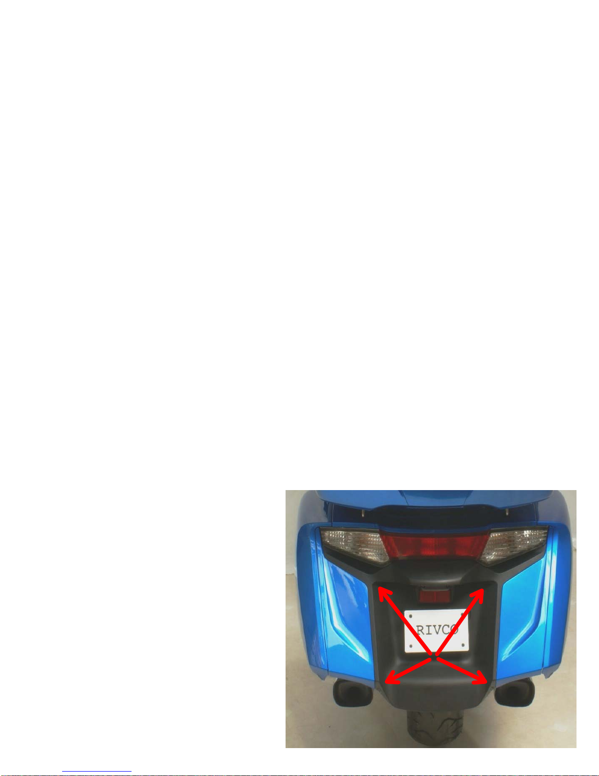
10. Remove the license plate and its mounting bracket from the rear fender. Install the license plate bracket onto
the supplied relocation bracket as shown in photo (10). Place two of the remaining supplied ¼” washers over
the studs on the license plate bracket (photo 10A) then the license plate relocating bracket (photo 10B).
Reinstall the original nuts onto the studs and tighten securely. On the outside of the fender reinstall the two
original flanged washers into the license plate mounting holes. Reinstall the license plate mount with bracket
assembly so that it is raising the plate up to clear the hole in the fender using the two supplied 6 x 16 mm
button head screws and flange nuts supplied. Reinstall the license plate onto the bracket.
11. Replace the rear fender temporarily snapping it into place only. Install the tongue thru the hole. Adjust the
hitch receiver height to center the tongue in the opening by moving the lower end of the struts forward or back
in their slotted bolt holes. Carefully remove the tongue and rear fender, and tighten the lower strut bolts
securely. (35-38 ft lbs.) Next tighten the upper strut to frame mounting bolts securely. (25-28 ft lbs.).
12. Refer to the supplied wiring instructions for installation of the plug in sub harness, electronic trailer isolator
unit and 5 to 4 wire convertor (if needed) all sold separately.
Wiring components required for plug in wiring to trailer
Rivco pt# GL18007-38 Sub harness
Rivco pt# GL17007-IU Wiring Isolator
Rivco pt# EC07664 5 to 4 wire system convertor (if trailer uses a 4 wire system)
NOTE: Unless you have all LED lighting on your trailer it is STRONGLY recommended to use an electronic
trailer wiring isolator (not supplied) RIVCO pt# GL18007-IU. It is designed to draw the additional 7-10 amps
of power needed for the trailer’s lighting directly from the battery, not thru the brake, tail or turn signal
circuits of the motorcycle. The isolator senses when power is applied to these circuits and activates the trailer
lighting accordingly. It is a solid-state electronic device that will protect the motorcycle’s advanced electrical
systems. It will supply up to 10 amps per circuit to the trailer. NOTE! The isolator is designed for trailers with
a five-wire system, which, like the motorcycle will have separate turn signal bulbs. If the trailer you will be
towing has a four-wire system (combined brake and stop lights) you will also need to add a five-to-four wire
convertor in line before the isolator (not supplied) RIVCO pt# EC07664.

They can also be purchased at most auto parts stores but will not have our plug in connector and will need to
be spliced in line. You will also need our plug in wiring sub harness Rivco pt# GL18007-38 to connect the
motorcycles wiring to the isolator and or the 5 to 4 wire convertor.
13. Remove the sub harness from its package, familiarize yourself with the leads and plugs as well as the supplied
wiring diagram then install as follows.
14. Open the trunk lid and remove the four screws from the two “U” shaped wire hooks or latches that secure the
lid when closed (notice one side of the “U” is longer and needs to be reinstalled in the same manner. Put these
screws aside with the latches as they must NOT be mixed with the screws to be removed next or damage to
the lid can occur. Remove the 11 Phillips screws around the edge of the inner lid. Unplug the wire harness
from the box attached to the lid and set the lid aside.
15. On the wiring sub harness locate the two 2 pin connectors with the green and blue wires. On the inside of the
trunk lid locate the three 2 pin connectors. Unplug the Blue connector on the bike that has a Brown wire with a
White stripe and a solid Green wire. Plug the two pin connectors with the Green wire into these connectors.
Locate and unplug the White connector that has a green with Yellow striped and a solid Green wire on the
bike. Plug the other remaining lead from the sub harness with the Blue wire into these connectors.
16. Route the wire loom from the sub harness along the bikes wire harness down the inside of the trunk, along the
right speaker and then down to the bikes frame. Secure the sub harness to the bikes wire harness using the
small cable ties provided. Under the seat in the passenger area, locate the large plastic box with many wire
looms going to it - this is the relay bank. Behind it there is a clear plastic sleeve with connectors inside it. In
this sleeve there should be a red connector and module and a black module with a 3 pin connector. Unplug the
black module, connect the 3 pin plug with the Brown and Yellow wires from the sub harness to the bike then
plug the module back into the connector on the sub harness. Place the wires neatly back in place inside the
clear sleeve and behind the relay bank.
17. Plug the remaining connector from the sub harness into the mating connector on the five to four convertor (if
you are using one, Rivco pt# EC07664) then the connector on the isolator (Rivco pt# GL18007-IU described
above) or from the sub harness to the isolator directly if not using a 5 to 4 wire convertor. Place the isolator
(and 5 to 4 wire convertor if used) as far to the rear of the inner fender as possible and down out of the way so
the seat will not come in contact with it when replaced and the wires will reach to where you will want your
trailer plug. Secure it in place with the supplied double-sided tape or a cable tie. Route the remaining wires
from the sub harness that will go to the trailer between the inner fender and the trunk, back towards the rear
fender, down along the strut of the hitch and ending up at below the receiver of the hitch. Use several of the
supplied cable ties to secure the harness.
18. The Black wire with the ring terminal is a ground. Attach the ring terminal to any of the nearby 6 MM (8 or
10MM wrench size) bolts on the frame. Route the red wire to the battery (+) positive terminal. Connect the
supplied fuse wire and holder to the battery (+) positive terminal. Cut the red wire to the desired length, strip
and crimp to the connector on the fuse holder’s wire.
19. The trailer plug is not provided with the isolator as there are many different types used. We recommend the
use of a loose plug vs. a mounted receptacle leaving enough wire for the plug to be outside of the fender.
When not plugged into the trailer the connector can be stored securely by routing it thru the hitch pin clip.
Follow the color code/function label on the isolator and or the supplied wiring diagram to make the proper
connections to your particular trailer plug.

20. Using a test light or meter turn on the ignition and test the tail, brake and turn signal functions at the
appropriate colored wires at the end of the isolator harness where you will be attaching your trailer plug.
Connect your trailer plug to the harness to obtain the correct light functions. We recommend the use of a
loose plug vs. a mounted receptacle leaving enough wire for the plug to be outside of the fender when in use.
When not plugged into the trailer the connector can be stored securely by routing it thru the hitch pin clip.
21. Installing tongue and hitch pin: Before reinstalling the rear fender permanently,practice installing the hitch
pin into the receiver and tongue as described by the following procedure; refer to photo #9, this will help you
to better visualize how to install the tongue and pin when the fender is installed. Place one hand on the
backside of the receiver slot, and with the tongue in the other hand push the tongue into the receiver until it is
flush with the back of the slot. Insert the supplied pin through the receiver and tongue from the bottom-up to
align the holes in the receiver with the hole in the tongue, and remove the pin. Now install the pin from the top
down by holding the pin in one hand with two fingers and guiding it to the hole with two fingers from your
other hand as shown in photo #9. Install the bowtie clip into the hole at the bottom of the pin being sure the
clip is fully engaged to its locking position.
22. Replace the side covers, rear fender, backrest, trunk inner lid and latches, seat (be sure to plug in heated seat
cord) and any other parts removed earlier.
23. Safety chain hook holes are provided on the vertical flange of the main hitch frame just below the receiver
block.
TRAILER TOWING GUIDELINES AND SAFETY
Remember that this is only a guide and should be supplemented with your own common sense for safe operation.
WARNING: TOWING A TRAILER BEHIND A MOTORCYCLE IS DONE SO AT YOUR OWN RISK AND INCREASES
THE LIKELIHOOD OF INJURY OR DEATH TO BOTH OPERATOR AND PASSENGER DUE TO INCREASED RISK
AND EXPOSURE. FAILURE TO OBSERVE THE FOLLOWING WILL FURTHER INCREASE THE RISK OF INJURY OR
DEATH TO OPERATOR AND PASSENGER.
(A) ALL HIGHWAY SAFETY WARNINGS, RULES AND LAWS,
(B) MAINTENANCE AND OPERATION INSTRUCTIONS ASSOCIATED
WITH THIS HITCH OR YOUR TRAILER,
(C) POSTED SPEED AND ROAD CONDITION WARNINGS,
(D) SAFE RIDING PRACTICES AND PROCEDURES
We are aware of no current state or federal guidelines for pulling a trailer with a motorcycle. We suggest when pulling
and loading a trailer that you do not exceed the manufacturers Gross Vehicle Weight and tongue weight limits. When
pulling a trailer with a motorcycle, extra distance must be allowed for stopping. When cornering, use slower speeds
and a wider angle of attack. Use extra caution at all times, particularly if the road surface is wet or slippery. Splitting
lanes with a trailer is HIGHLY discouraged and is ILLEGAL in many states.
IMPORTANT: AS A SAFETY PRECAUTION CHECK THE FOLLOWING BEFORE EVERY TRIP:
*Visual Inspection of Hitch and Mounting Bolts. *Safety Chains are Attached Properly.
*Trailer Lights Function Properly. *Hitch Pin on & Clipped. *Check Air Pressure In Trailer Tires.
Thank you for purchasing a RIVCO Product!
#1
#2
A

#3
#4
B
A
#5
#6
#7
#8
C
B
A
A
D
B
C

#9

BLUE (R TURN)
ORANGE (L TURN)
BROWN (TAIL)
BLACK (GROUND)
BLACK (GROUND)
10A
FUSE
GROUND
NEG (-)
RED
BATTERY
POS (+)
10A
FUSE
BLUE (R+STOP)
ORANGE (L+STOP)
BROWN (TAIL)
GREEN (ACC)
BLACK (GROUND)
RED
BATTERY
POS (+)
GROUND
NEG (-)
BLUE
ORANGE
BROWN
OPTIONAL
ACC POWER
(+) SWITCHED
GREEN
WHITE
BLACK
BLACK
GROUND
NEG (-)
GREEN (TAIL)
GREEN (TAIL)
YELLOW (R TURN)
BROWN (L TURN)
WHITE/YELLOW (R+STOP)
WHITE/BROWN (L+STOP)
BLUE (STOP)
GREEN (STOP)
BLUE (R TURN)
ORANGE (L TURN)
BROWN (TAIL)
GREEN (STOP)
4-PIN PLUG
4-PIN PLUG
BLUE (STOP)
YELLOW
(R TURN)
YELLOW
(R TURN)
BLUE (STOP)
GL18007-38 (2012 & UP HONDA GL1800 GOLDWING)
ISOLATOR WIRING DIAGRAM
GL18007-38 (2012 & UP HONDA GL1800 GOLDWING)
WITH 5-TO-4 WIRE CONVERTER & ISOLATOR
BROWN
(L TURN)
GREEN (TAIL)
BROWN
(L TURN)
GREEN (TAIL)
4-PIN PLUG
3-PIN CONNECTOR
(UNDER SEAT)
BLACK
MODULE
BLUE
GREEN
BLUE GREEN
GREEN
WHITE
2-PIN CONNECTOR
(INSIDE TRUNK LID)
2-PIN CONNECTOR
(INSIDE TRUNK LID)
WHITE
GREEN
SUBHARNESS
GL18007-38
3-PIN CONNECTOR
(UNDER SEAT)
2-PIN CONNECTOR
(INSIDE TRUNK LID)
2-PIN CONNECTOR
(INSIDE TRUNK LID)
5-TO-4
WIRE
CONVERTER
#EC07664
GREEN GREEN
WHITE
WHITE
GREEN
BLUE
BLUE
GREEN
BLACK
MODULE
SUBHARNESS
GL18007-38
BROWN/WHITE
GREEN/YELLOW GREEN/YELLOW
BROWN/WHITE
BROWN/WHITE BROWN/WHITE
GREEN/YELLOW
GREEN/YELLOW
TO
BIKE
ISOLATOR
GL18007-IU
TO
TRAILER
TO
BIKE
ISOLATOR
GL18007-IU
TO
TRAILER
Other Rivco Automobile Accessories manuals


