RivieraPool Starto 2.0 User manual

Technical Information WP 11 B Version: 11/10/2016
Instruction Manual
PORTABLE SPAS
RIVIERA SPAS STRATO,WAVE
Prefabricated S w i m m i n g P o o l S
.
w h i r l P o o l S
ATTENTION:
This is a preliminary version;
subject to modications. If you have
any questions please contact our
service department.

2
Content
1. Technical Drawings
1.1 Strato 2.0 .................................................................................................................................................... Page 3
1.2 Strato 2.3 .................................................................................................................................................... Page 4
1.3 Wave 2.0 ..................................................................................................................................................... Page 5
2. General Information / Requirements on site
2.1 Specific use and purpose ..................................................................................................................... Page 6
2.2 Power supply ............................................................................................................................................ Page 6
2.3 Fresh water................................................................................................................................................. Page 6
2.4 Waste water............................................................................................................................................... Page 7
2.5 Delivery....................................................................................................................................................... Page 7
2.6 Noise insulation....................................................................................................................................... Page 7
3. Start-up and Operation
3.1 Positioning the spa.............................................................................................................................. Page 8
3.2 Mounting the cover................................................................................................................................ Page 8
3.3 Start-up and Operation......................................................................................................................... Page 9
3.4 Switching the power supply on and off for the first time ....................................................... Page 9
3.5 Operation of the massage jets ........................................................................................................... Page 10
3.6 Operating the digital display ........................................................................................................ Page 11
3.6.1 The main screen ..................................................................................................................................... Page 11
3.6.2 Setting the temperature ..................................................................................................................... Page 13
3.6.3 The Spa screen (user functions) ....................................................................................................... Page 13
3.6.4 General Keys ............................................................................................................................................. Page 14
3.6.5 Screenshot: Settings .............................................................................................................................. Page 17
3.6.6 Settings for the temperature ranges ................................................................................................ Page 17
3.6.7 Filling the spa ........................................................................................................................................... Page 18
3.6.8 Filtration einstellen.................................................................................................................................. Page 19
3.6.9 Frost protection....................................................................................................................................... Page 19
3.6.10 Auxiliary control panel (s) .................................................................................................................... Page 20
3.6.11 Locking the operating keys ................................................................................................................. Page 20
3.6.12 The Fault Log ........................................................................................................................................... Page 21
3.6.13 Information................................................................................................................................................ Page 22
3.6.14 The cleaning cycle .................................................................................................................................. Page 23
3.6.15 Language ................................................................................................................................................... Page 23
3.6.16 General Information ............................................................................................................................... Page 24
3.6.17 Error messages for heating .................................................................................................................. Page 25
3.6.18 Error messages for sensors ................................................................................................................. Page 26
3.6.19 Error messages for the main system ................................................................................................. Page 27
3.6.20 Things to remember ............................................................................................................................ Page 28
3.7 Audio System ......................................................................................................................................... Page 29
4. Care and maintenance
4.1 Care Manual Whirlpool covers ........................................................................................................... Page 30
4.2 Care of headrest and pillows .............................................................................................................. Page 31
4.3.1 Water maintenance ............................................................................................................................... Page 32
4.3.2 Filtration ..................................................................................................................................................... Page 32
4.3.3 Flocculation............................................................................................................................................... Page 32
4.3.4 pH Values.................................................................................................................................................... Page 33
4.3.5 Disinfection ............................................................................................................................................... Page 33
4.3.6 Adding fresh water, changing the water, emptying the whirlpool ....................................... Page 33
4.3.7 Cleaning and Maintenance of the surface..................................................................................... Page 33
4.4 Care and Cleaning of the Resysta panels ....................................................................................... Page 34
4.5 Winterising ................................................................................................................................................ Page 34
4.5.1 Winterising - Sleep mode ................................................................................................................... Page 34
4.5.2 Complete winterisation ....................................................................................................................... Page 35
5. Instructions for bathing Page 36
6. Schematics Page 37
7. Checklist Page 39
3
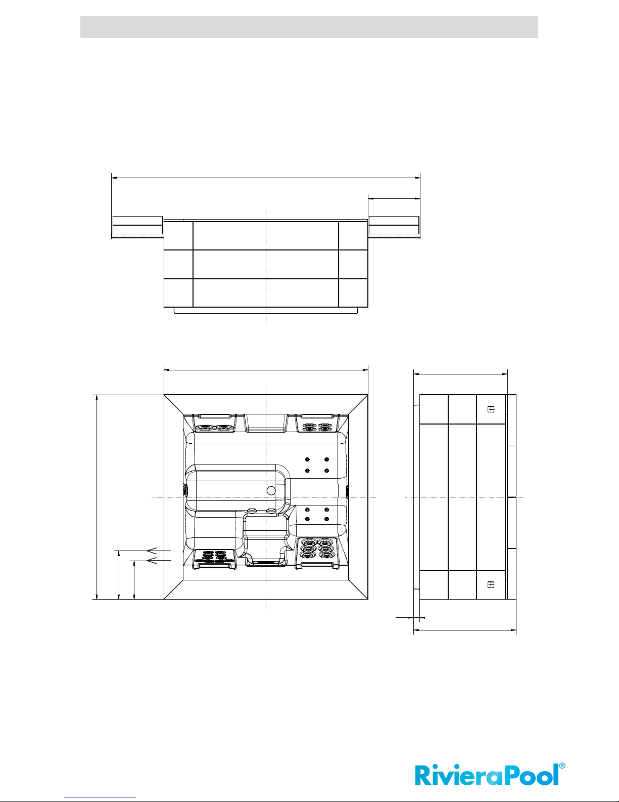
970
2110
Technik
540
ca. 3190
65
1060
(inkl. Daybed)
1
2
2110
430
500
Aufstellbereich mit ausgezogenen Hardtopauflagen
RivieraSpas - Portable
1.1 Strato 2.0
1. Technical Drawings
Information: Additional information is available from our technical customer service department.
We reserve the right, to perform production changes and improvements without prior notice In terms of technical
progress.
(incl. Daybed)
technique
Required space for pool with extracted supports for the pool cover
4
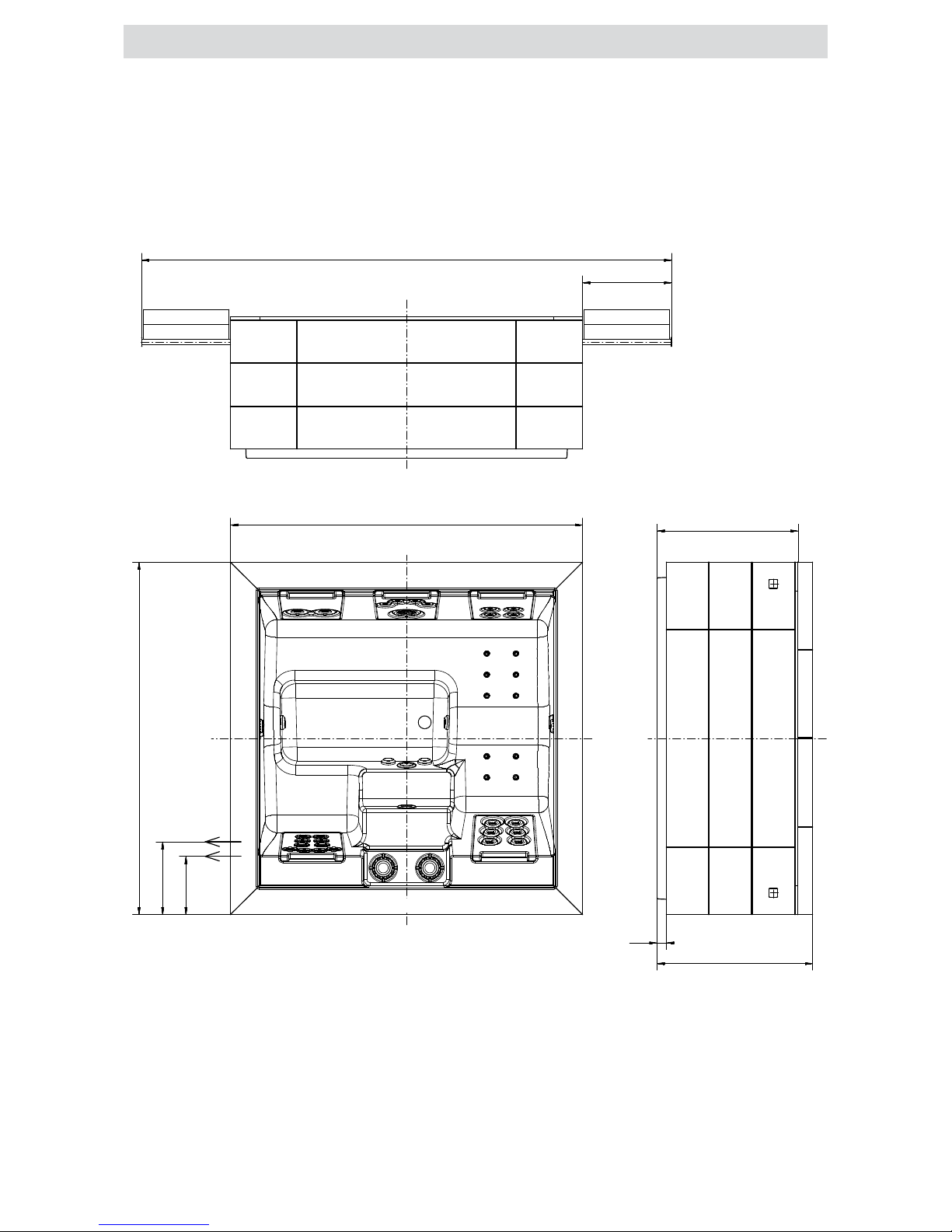
970
2420
610
ca . 3640
65
1070
1
2
430
530
2420
Technik
Aufstellbereich mit ausgezogenen Hardtopauflagen
(inkl. Daybed)
RivieraSpas - Portable
1.2 Strato 2.3
(incl. Daybed)
technique
Required space for pool with extracted supports for the pool cover

5
970
2390
Technik
610
ca. 3640
65
1070
1
2
430
530
2390
Aufstellbereich mit ausgezogenen Hardtopauflagen
(inkl. Daybed)
RivieraSpas - Portable
1.3 Wave 2.0
Required space for pool with extracted supports for the pool cover
(incl. Daybed)
technique
Table of contents
Other RivieraPool Hot Tub manuals

Popular Hot Tub manuals by other brands


 owner's manual")


CalderaSpas
CalderaSpas CalderaSpas Utopia Series owner's manual

anko
anko SS-601A user manual

CalderaSpas
CalderaSpas CANTABRIA owner's manual

Dimension One Spas
Dimension One Spas HYDRO SPORT Installation and owner's guide

Bestway
Bestway Lay-Z-Spa Maldives HydroJet Pro manual

Dimension One Spas
Dimension One Spas Nautilus Specifications