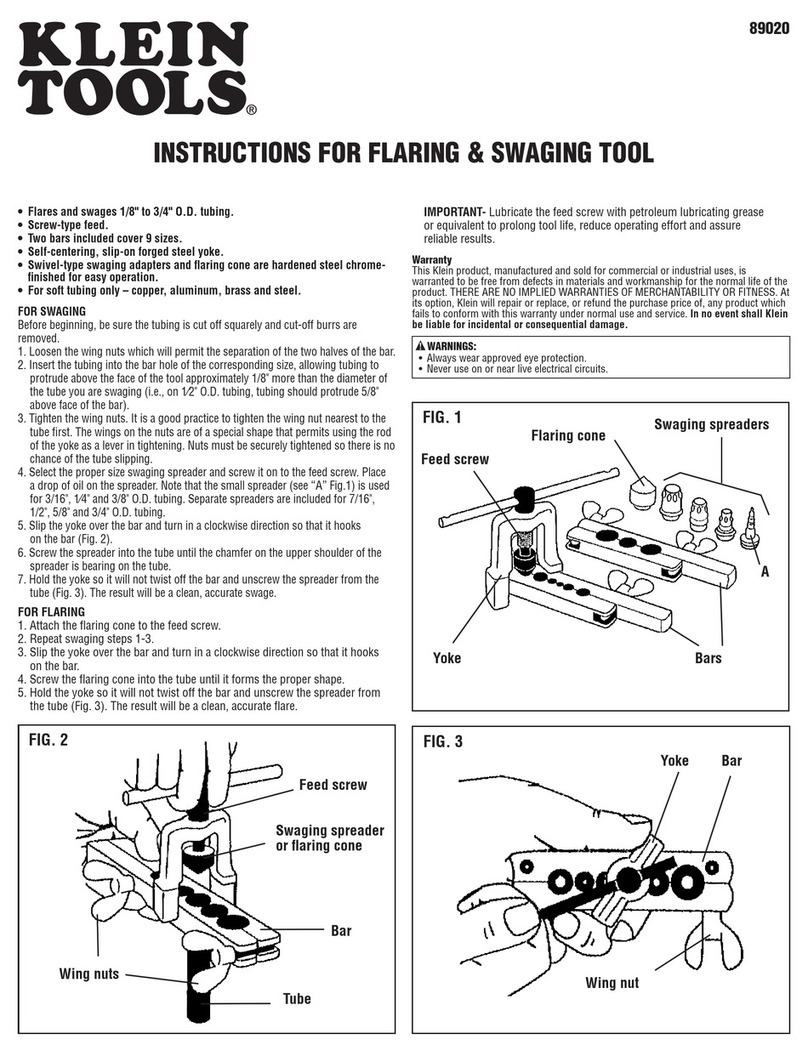
Rivtec RNT 120 User manual


1
INTENDED USE
GLOSSARY OF TERMS AND SYMBOLS
SAFETY PRECAUTIONS
SAFETY INSTRUCTIONS
FEATURES
SPECIFICATIONS
DIMENSIONS
MAIN PARTS
PARTS LIST
OPERATION INSTRUCTIONS
MAINTENANCE
TROUBLESHOOTING
DISPOSAL
EC DECLARATION OF CONFORMITY
PAGE INDEX
1. INTENDED USE
3. SAFETY PRECAUTIONS
2. GLOSSARY OF TERMS AND SYMBOLS
1
1
1-3
3
4
5
6
7
8-9
10-14
15-18
19-21
21
22
1.
2.
3.
4.
5.
6.
7.
8.
9.
10.
11.
12.
13.
14.
This pneumatic-hydraulic rivet nut tool is designed to be driven by the appropriate compressed air pressure for secure
fastening a rivet nut containing enough female threads in the thin base metals and pipes with weldless, tapping-free and
one-side work in order to fasten with a bolt or a screw. The applications are widely used in the production and repairs of
aircraft, automobiles & vehicles, boats, construction, electric/electronic appliances, even the DIY work, etc.
This pneumatic-hydraulic rivet nut tool is designed and produced primarily for the professional users, the non-professional
users must read the operation manual thoroughly, and consult the manufacturer, authorized local agent or distributor for
real understanding. A half hour long hands-on training session with qualified personnel is essential and strongly
recommended before using this tool.
1.
2.
For multiple hazards, read and understand the safety instructions before installing, operating, repairing, maintaining,
changing accessories, or working near the assembly power tool. Failure to do so can result in serious bodily injury.
Only qualified and trained operators should install, adjust or use the assembly power tool.
Do not modify this assembly power tool. Modifications can reduce the effectiveness of safety measures and increase the
risks to the operator.
Do not discard the safety instructions; give them to the operator.
Do not use the assembly power tool if it has been damaged.
Tools shall be inspected periodically to verify that the ratings and markings required, by this part of ISO 11148 are legibly
marked on the tool, and that listed in this manual. The employer/user shall contact the manufacturer to obtain replacement
marking labels when necessary.
1.
2.
3.
4.
5.
6.
: READ MANUAL carefully prior to using
this tool.
: EYE PROTECTION IS REQUIRED when
using this tool.
: HEARING PROTECTION IS REQUIRED
when using this tool.
: HAND PROTECTION IS REQUIRED
when using this tool.
WARNING
3.1 SAFETY PRECAUTIONS

2
Disconnect the assembly power tool from the energy source when changing inserted tools or accessories.
Be aware that failure of the work piece or accessories, or even of the inserted tool itself can generate high-velocity projectiles.
Always wear impact-resistant eye protection during operation of the tool. The grade of protection required should be
assessed for each use.
The risks to others should also be assessed at this time.
Ensure that the work piece is securely fixed.
Check that the means of protection from ejection of fastener and/or stem is in place and is operative.
There is possibly forcible ejection of installed nuts from the front of the assembly power tool.
1.
2.
3.
4.
5.
6.
7.
3.2 PROJECTILE HAZARDS
Use of the tool can expose the operator's hands to hazards, including crushing, impacts, cuts and abrasions and heat.
Wear suitable gloves to protect hands.
Operators and maintenance personnel shall be physically able to handle the bulk, weight and power of the tool.
Hold the tool correctly; be ready to counteract normal or sudden movements and have both hands available.
Maintain a balanced body position and secure footing.
Release the start-and-stop device in the case of an interruption of the energy supply.
Use only oils and lubricants recommended by the manufacturer.
Avoid unsuitable postures, as it is likely for these positions not to allow counteracting of normal or unexpected movement
of the tool.
If the assembly power tool is fixed to a suspension device, make sure that the fixation is secure.
Beware of the risk of crushing or pinching if nose equipment is not fitted.
1.
2.
3.
4.
5.
6.
7.
8.
9.
3.3 OPERATING HAZARDS
When using an assembly power tool, the operator can experience discomfort in the hands, arms, shoulders, neck or other
parts of the body.
While using an assembly power tool, the operator should adopt a comfortable posture whilst maintaining a secure footing
and avoiding awkward or off-balance postures. The operator should change posture during extended tasks; this can help
avoid discomfort and fatigue.
If the operator experiences symptoms such as persistent or recurring discomfort, pain, throbbing, aching, tingling,
numbness, burning sensations or stiffness, these warning signs should not be ignored. The operator should tell the
employer and consult a qualified health professional.
1.
2.
3.
3.4 REPETITIVE MOTIONS HAZARDS
Disconnect the assembly power tool from the energy supply before changing the inserted tool or accessory.
Use only sizes and types of accessories and consumables that are recommended by the manufacturer of assembly power
tools; do not use other types or sizes of accessories or consumables.
1.
2.
3.5 ACCESSORY HAZARDS
Exposure to high noise levels can cause permanent, disabling hearing loss and other problems, such as tinnitus (ringing,
buzzing, whistling or humming in the ears). Therefore, risk assessment and the implementation of appropriate controls for
these hazards are essential.
Appropriate controls to reduce the risk may include actions such as damping materials to prevent work piece from “ringing”.
Use hearing protection in accordance with employer's instructions and as required by occupational health and safety regulations.
Operate and maintain the assembly power tool for non-threaded mechanical fasteners as recommended in the instruction
handbook, to prevent an unnecessary increase in the noise level.
Select, maintain and replace the consumable/inserted tool as recommended in the instruction handbook, to prevent an
unnecessary increase in noise.
If the power tool has a silencer, always ensure that it is in place and in good working order when the power tool is being
operated.
1.
2.
3.
4.
5.
6.
3.7 NOISE HAZARDS
Slips, trips and falls are major causes of workplace injury. Be aware of slippery surfaces caused by use of the tool and also
of trip hazards caused by the air line or hydraulic hose.
Proceed with care in unfamiliar surroundings. There can be hidden hazards, such as electricity or other utility lines.
The assembly power tool is not intended for use in potentially explosive atmospheres and is not insulated against contact
with electric power.
Ensure that there are no electrical cables, gas pipes, etc., which can cause a hazard if damaged by use of the tool.
1.
2.
3.
4.
3.6 WORKPLACE HAZARDS

3
4. SAFETY INSTRUCTIONS
Exposure to vibration can cause disabling damage to the nerves and blood supply of the hands and arms.
Wear warm clothing when working in cold conditions and keep your hands warm and dry.
If you experience numbness, tingling, pain or whitening of the skin in your fingers or hands, stop using the assembly power
tool, tell your employer and consult a physician.
Support the weight of the tool in a stand, tensioner or balancer, because a lighter grip can then be used to support the tool.
1.
2.
3.
4.
3.8 VIBRATION HAZARDS
Air under pressure can cause severe injury:
(1) Always shut off air supply, drain hose of air pressure and disconnect tool from air supply when not in use, before
changing accessories or when making repairs;
(2) Never direct air at yourself or anyone else.
Whipping hoses can cause severe injury. Always check for damaged or loose hoses and fittings.
Cold air shall be directed away from hands.
Whenever universal twist couplings (claw couplings) are used, lock pins shall be installed and Whip Check Safety Cables
shall be used to safeguard against possible hose-to-tool or hose-to-hose connection failure.
Do not exceed the maximum air pressure stated on the tool.
Never carry an air tool by the hose.
The limitations of environmental conditions on Tool are the temperature 0-40˚C (32-104˚F), and Tool can
not be used in the water.
Tool weight over 2.0 kg or 4.4 lb is suggested to be supported by two hands, one hand to hold handle grip
and the other hand to support the bottom of Tool, whilst lifting or operating Tool.
1.
2.
3.
4.
5.
6.
7.
8.
The tool must be checked and maintained in a safe working condition at all times.
Do not use the tool outside the intent of design and use.
Do not dismantle the tool without prior reference to this manual.
Any modification to the tool and tool parts shall be prohibited.
Always use original spare parts to ensure safe operation and satisfactory performance.
Be sure to disconnect the tool from air supply before attempting to adjust, change nosepiece or dismantle tool’s parts.
For safety work, the operator and other persons in the vicinity are always required to wear the safety goggles to protect
against spent mandrel ejection.
Be sure to adopt a firm footing or stable position before and during operating the tool.
Do not point the tool towards any person(s) or operator.
Do not operate the tool without firmly installing and locking the threaded mandrel (1), nosepiece lock nut (4), stroke
adjuster lock nut (6), front head (7), oil cylinder end cap (25), noise silencer lock nut (34), valve end cap (51), air cylinder
end cap (59), air inlet end cap (61), and speed-adjust swivel air fitting (62).
Be sure to properly adjust the Stroke.
The Operating Air Pressure shall not exceed 7.0 bar or 100 psi.
Excessive priming of hydraulic oil in the tool should be avoided.
After setting each rivet nut, turn the rotation knob (26) counterclockwise to unscrew the threaded mandrel (1) from the
fastened rivet nut, so that the same size rivet nut can be installed onto the threaded mandrel (1) by turning knob clockwise,
and then to continue the next fastening work.
Take care to ensure the deformed Rivet Nut is not to create any hazards.
Ensure that noise silencer (33) and vent holes of noise silencer lock nut (34) do not become blocked or covered, and that
air hose is always in good condition.
Always keep the tool and grip (64) dry and clean for the best possible grip and operation.
Take care to avoid entanglement of loose clothes, ties, long hair, cleaning rags, etc. In the moving parts of the tool.
When carrying the tool from place to place, always keep hands away from the trigger (35, 35L) to avoid inadvertent start up.
Take care to use the tool. Do not drop the tool. Do not use the tool as a hammer or other uses that will damage and wear
the tool.
The tool should be examined at regular intervals for function and damage. Any question regarding the correct operation of
tool and operator safety should consult the manufacturer, authorized local agent or distributor.
1.
2.
3.
4.
5.
6.
7.
8.
9.
10.
11.
12.
13.
14.
15.
16.
17.
18.
19.
20.
21.
3.9 SAFETY INSTRUCTIONS FOR PNEUMATIC-HYDRAULIC RIVET NUT POWER TOOLS

4
6. SPECIFICATIONS
Traction Force: 21,000 N at 6.2 bar or or 4,720 lbf at 90 psi compressed air pressure, and 23,500 N at 7.0 bar or 5,280 lbf
at 100 psi compressed air pressure.
Stroke: 0 ~ 9 mm or 0 ~ 0.36˝.
Working Compressed Air Pressure: 5.5 ~ 7.0 bar or 80 ~ 100 psi.
Air Consumption: Approx. 3.10 liter per rivet nut or 0.11 cuft per rivet nut.
Hydraulic Oil, ISO VG-46 or VG-32: Approx. 40 ml.
Working Temperature: 0 - 40 ˚C or 32 - 104 ˚F.
Noise Level:
Sound pressure level, LPA: 72.5 dB(A)
Uncertainty : KPA = 3.0 dB
Sound power level, LWA: 83.5 dB(A)
Uncertainty : KWA = 3.0 dB
Vibration:
Hand-arm vibration value: Less than 2.5 m/s²
Uncertainty : K = 1.5 m/s²
Air Inlet: 1/4˝ PT or 1/4˝ NPT or other specified thread.
Hose Size: Inner diameter 10 mm or 3/8˝.
Net Weight: Approx. 2.24 kg / 4.93 lb.
Standard Parts: 6 or 7 Threaded Mandrels (M4, M5, M6, M8, M10, M12 or 8-32, 10-24, 10-32, 1/4-20, 5/16-18, 3/8-16,
1/2-13) (1), 6 Nosepieces (M4, M5, M6, M8, M10, M12 or #8, #10, 1/4, 5/16, 3/8, 1/2) (3), Speed-Adjust Swivel Air Fitting
(62), Oil Bottle (63, without Oil), Service Wrench (65), Small Rule (66), Fixing-Hole Pin (67), Pin Retainer (68), Oil Injector
(69, without Oil), Parts Plastic Box (70).
Additional Standard Parts: Threaded Sockets (M4, M5, M6, M8 or 8-32, 10-24, 10-32, 1/4-20, 5/16-18) (2).
RIVETING CAPACITY:
1.
2.
3.
4.
5.
6.
7.
8.
9.
10.
11.
12.
13.
14.
Aluminum Steel Stainless
Steel/Inox
Thread Size
Rivet Nut/Bolt
Material
Remark: Work piece hole diameter should be 0.1 mm or 0.004˝ larger than rivet nut outer diameter.
5. FEATURES
This pneumatic-hydraulic rivet nut tool features powerful traction force 21,000 N at 6.2 bar or 4,720 lbf at 90 psi, and
23,500 N at 7.0 bar or 5,280 lbf at 100 psi, and equips with interchangeable 6 or 7 threaded mandrels and 6 nosepieces
for setting M4 ~ M12 Rivet Nut or 8-32 ~ 1/2 Rivet Nut in all materials (aluminum, copper, steel and stainless steel), also
can set M4 ~ M8 Rivet Bolt (Stud) or 8-32 ~ 5/16 Rivet Bolt (Stud) in all materials with optional threaded sockets. The
optional M4 ~ M8 or 8-32 ~ 5/16 threaded sockets are available on request.
Unique Adjustable Fastening Speed Design can control slow or fast fastening speed. Slow speed is ideal for setting
rivet nut in the repaired painted car body or thin work piece, and other same application purpose.
Special Hand Spin-Pull-Hand Spin Design to screw rivet nut onto or unscrew fastened rivet nut from threaded mandrel
by hand rotation that can prevent the repaired painted car body or thin work piece from being scratched. Straight Pulling
can ensure nice fastening work.
Adjustable Stroke Design to prevent rivet nut from insufficient fastening or rivet nut from being stuck with threaded mandrel.
Innovative Fix-Hole Design to offer great solution to solve the headache problem of rivet nut stuck with threaded mandrel
and great assistance of exchanging threaded mandrels.
Shock-Free Design to minimize hand fatigue.
Innovative Noise Silencer Design for working pleasure.
Smart Twin Air Inlets to meet individual operating hobby, such as the right-handed operators or left-handed operators.
Oil Cylinder Body are made of super strength forged aluminum alloy and Air Cylinder Body are made of high strength
aluminum alloy, Inner walls all have wear-resistant mirror finish for durability.
Oil Piston Rod and Air Piston Rod all have hard chrome plating and wear-resistant mirror finish for speedy motion.
High grade Steel Alloy Key Parts
(threaded mandrel, etc.) with advanced heat treatment for strength and durability.
Valuable
Hard Anodized finish on Forged Aluminum
Hydraulic Oil Cylinder Body and Powder Coating finish on Air
Cylinder Body for nice looking and better scratch-resistant.
PAHs-Free (non-toxic to hand skin) Soft Plastic Hand Grip for comfortable and safe operation.
1.
2.
3.
4.
5.
6.
7.
8.
9.
10.
11.
12.
13.
M4 x 0.7 or 8-32 Rivet Nut / Rivet Bolt (Stud)
M5 x 0.8 or 10-24, 10-32 Rivet Nut / Rivet Bolt (Stud)
M6 x 1.0 or 1/4-20 Rivet Nut / Rivet Bolt (Stud)
M8 x 1.25 or 5/16-18 Rivet Nut / Rivet Bolt (Stud)
M10 x 1.5 or 3/8-16 Rivet Nut
M12 x 1.75 or 1/2-13 Rivet Nut

5
7. DIMENSIONS
39.0
UNIT: mm
240.3
303.4
Ø91.0
121.4
115.2

8. MAIN PARTS
2
Threaded
Socket
Stroke
Indicator
Rivet Bolt
Rivet Nut
7
Front Head
Fixing Hole
6
Stroke
Adjuster
Lock Nut
37
Trigger Lever
34
Noise Silencer
Lock Nut
43AY
Valve Assembly
59
Air Cylinder End Cap
30
Air Cylinder
35 Trigger
Air Inlet
4
Nosepiece
Lock Nut
24
Hanging Bracket
62
Speed-Adjust
Swivel Air Fitting
62
Speed-Adjust
Swivel Air Fitting
15
Oil Cylinder
64
Grip
26
Rotation Knob
26
Rotation Knob
1
Threaded
Mandrel
3
Nosepiece
5
Stroke
Adjuster
35L
Trigger,
Long Type
6

9. PARTS LIST
63
65 66 67 68
7069
1 2 3
1
3
4
5
6
7
8
9
10
10A
11 12 13 13
14
27
29
28
15
64
18
16
17
24
19
25
20
26
21
22
23
30
32
32A
42
35
40
38
36
41
34 33
31
60
61
37
39
43
44
45
29
46
47
48
49
50
51
52
53
55
58
59
54
57
56
62
35L
40
38 35AY
(35~41)
35LAY
(35L~41)
43AY
(29, 42~51)
55AY
(52~57)
18AY(18~20)
15.5
mm
3/5˝
1
9
8
11 12
18
15
7

No.
1-M4
1-M5
1-M6
1-M8
1-M10
1-M12
1-832
1-1024
1-1032
1-1420
1-51618
1-3816
1-1213
2-M4
2-M5
2-M6
2-M8
2-832
2-1024
2-1032
2-1420
2-51618
3-M4
3-M5
3-M6
3-M8
3-M10
3-M12
3-8
3-10
3-14
3-516
3-38
3-12
4
5
6
7
8
9
10A
10
11
12
13
14
15
16
17
18
19
20
18AY
21
22
ANS120-01-M4
ANS120-01-M5
ANS120-01-M6
ANS120-01-M8
ANS120-01-M10
ANS120-01-M12
ANS120-01-832
ANS120-01-1024
ANS120-01-1032
ANS120-01-1420
ANS120-01-51618
ANS120-01-3816
ANS120-01-1213
ANS120-02-M4
ANS120-02-M5
ANS120-02-M6
ANS120-02-M8
ANS120-02-832
ANS120-02-1024
ANS120-02-1032
ANS120-02-1420
ANS120-02-51618
ANS120-03-M4
ANS120-03-M5
ANS120-03-M6
ANS120-03-M8
ANS120-03-M10
ANS120-03-M12
ANS120-03-8
ANS120-03-10
ANS120-03-14
ANS120-03-516
ANS120-03-38
ANS120-03-12
ANS120-04
ANS120-05
ANS120-06
ANS120-07
ANS120-08
ANS120-09
ANS120-10A
ANS120-10
ANS120-11
ANS120-12
ANS120-13
ANS120-14
ANS120-15
ANS120-16
ANS120-17
ANS120-18
ANS120-19
ANS120-20
ANS120-18AY
ANS120-21
ANS120-22
23
24
25
26
27
28
29
30
31
32
32A
33
34
35
35L
36
37
38
39
40
41
35AY
35LAY
42
43
44
45
29
46
47
48
49
50
51
43AY
52
53
54
55
56
57
55AY
58
59
60
61
62
63
64
65
66
67
68
69
70
ANS120-23
ANS120-24
ANS120-25
ANS120-26
ANS120-27
ANS120-28
ANS120-29
ANS120-30
ANS120-31
ANS120-32
ANS120-32A
ANS120-33
ANS120-34
ANS120-35
ANS120-35L
ANS120-36
ANS120-37
ANS120-38
ANS120-39
ANS120-40
ANS120-41
ANS120-35AY
ANS120-35LAY
ANS120-42
ANS120-43
ANS120-44
ANS120-45
ANS120-29
ANS120-46
ANS120-47
ANS120-48
ANS120-49
ANS120-50
ANS120-51
ANS120-43AY
ANS120-52
ANS120-53
ANS120-54
ANS120-55
ANS120-56
ANS120-57
ANS120-55AY
ANS120-58
ANS120-59
ANS120-60
ANS120-61
ANS120-62
ANS120-63
ANS120-64
ANS120-65
ANS120-66
ANS120-67
ANS120-68
ANS120-69
ANS120-70
Hanging Bracket O-ring
Hanging Bracket
Oil Cylinder End Cap
Rotation Knob
Oil Cylinder Upper O-Ring
Oil Cylinder Back-Up Ring
Oil Cylinder Lower O-ring
Air Cylinder
Lock Screw
Oil Cylinder Lock Nut
Lock Nut O-Ring
Noise Silencer
Noise Silencer Lock Nut
Trigger
Trigger, Long Type (Option)
Trigger Link
Trigger Lever
Upper Link Pin
Lower Link Pin
Trigger Pin
Lever Pin
Trigger Assembly (35~41)
Trigger Assembly (35L~41), Long Type (Option)
Valve Pusher Upper O-ring
Valve Pusher
Valve Pusher Lower O-ring
Valve Pusher Spring
Valve Sleeve O-Ring
Valve Sleeve
Valve Ball O-ring
Valve Ball
Valve Spring
Valve End Cap O-ring
Valve End Cap
Valve Assembly (29, 42~51)
Buffer Ring
Air Piston Ring
Air Piston Rod
Air Piston
Lock Washer
Air Piston Lock Nut, Long Type
Air Piston Assembly (52~57)
Air Cylinder End Cap O-ring
Air Cylinder End Cap
Air Inlet End Cap O-ring
Air Inlet End Cap
Speed-Adjust Swivel Air Fitting
Oil Bottle (without Oil)
Grip
Service Wrench
Small Rule
Fixing-Hole Pin
Pin Retainer
Hydraulic Oil Injector (without Oil)
Parts Plastic Box
Threaded Mandrel, M4x0.7
Threaded Mandrel, M5x0.8
Threaded Mandrel, M6x1.0
Threaded Mandrel, M8x1.25
Threaded Mandrel, M10x1.5
Threaded Mandrel, M12x1.75
Threaded Mandrel, 8-32
Threaded Mandrel, 10-24
Threaded Mandrel, 10-32
Threaded Mandrel, 1/4-20
Threaded Mandrel, 5/16-18
Threaded Mandrel, 3/8-16
Threaded Mandrel, 1/2-13
Threaded Socket, M4x0.7 (Option)
Threaded Socket, M5x0.8 (Option)
Threaded Socket, M6x1.0 (Option)
Threaded Socket, M8x1.25 (Option)
Threaded Socket, 8-32 (Option)
Threaded Socket, 10-24 (Option)
Threaded Socket, 10-32 (Option)
Threaded Socket, 1/4-20 (Option)
Threaded Socket, 5/16-18 (Option)
Nosepiece, for M4
Nosepiece, for M5
Nosepiece, for M6
Nosepiece, for M8
Nosepiece, for M10
Nosepiece, for M12
Nosepiece, for #8
Nosepiece, for #10
Nosepiece, for 1/4
Nosepiece, for 5/16
Nosepiece, for 3/8
Nosepiece, for 1/2
Nosepiece Lock Nut
Stroke Adjuster
Stroke Adjuster Lock Nut
Front Head
Collet Case
Mandrel Seat
Snap Ring Washer
Snap Ring
Collet Case Lock Nut
Lock Nut
Oil Cylinder O-ring
Oil Cylinder Back-up Ring
Oil Cylinder
Sealing Washer
Oil Screw Plug
Oil Piston
Oil Piston O-ring
Oil Piston Back-up Ring
Oil Piston Assembly (18~20)
Large Return Spring
Small Return Spring
PART No. PART NAME No. PART No. PART NAME
8
1) Means wearing parts or possible missing parts.
2) Part No. 35 Trigger is the Standard Part, Part No. 35L Trigger Long Type is the Optional Part for choice.
3) Order Example: ANS120-01-M6 Threaded Mandrel M6x1.0, 10 pcs.
4) Part No. 32 Oil Cylinder Lock Nut needs to replace a new one after repeated fastening 3 ~ 4 times.
5) Part No. 32A Lock Nut O-Ring needs to replace a new one when dismantling Part No. 32 Oil Cylinder Lock Nut.
REMARKS:

Air Compressor
Air
Pressure
Regulator
Main Air
Supply Line
3 Meters or 10 Feet Maximum
Air
Filter
Air
Lubricator
Air
Hose
Tool
NOTE:
Drain
Daily
COMPRESSED AIR SUPPLY SYSTEM
10. OPERATION INSTRUCTIONS
The tool is well assembled and tested before delivery; however, the necessary setting and testing are still strongly suggested
before operating tool. Carefully read this OPERATION INSTRUCTIONS 10.2 - 10.9 to check the setting of tool, follow the 10.8
OPERATION PROCEDURE to do the pilot test before operating tool.
The compressed air pressure should be in the suggested working range; tool’s working threaded mandrel size, nosepiece
size, rivet nut size and work piece’s hole diameter must be well matched, so that the pilot test can verify the fastening work
is firmed or not.
1.
2.
10.1 SETTING AND TESTING
This pneumatic-hydraulic rivet nut tool is operated with compressed air at an optimum air pressure of 6.5 bar or 95 psi.
This pneumatic-hydraulic rivet nut tool is recommended to connect with COMPRESSED AIR SUPPLY SYSTEM including
air compressor, main air supply line, air preparation unit (air filter, air pressure regulator with gauge, air lubricator) and air
hose. These should be fitted within 3 meters or 10 feet from air pressure regulator to the tool to ensure maximum tool life
and minimum tool maintenance.
The air pressure regulator is used to adjust the operating air pressure not to exceed the maximum operating air pressure
7.0 bar or 100 psi.
The air hose should resist a minimum 150% of maximum operating air pressure (7.0 bar or 100 psi) produced in the
COMPRESSED AIR SUPPLY SYSTEM, that is to resist the highest air pressure 10.5 bar or 150 psi. The air hose should be
oil resistant, and have an abrasion resistant exterior. The air hose must have a minimum inner diameter of 10 mm or 3/8” .
Be sure to expel the accumulated dirt and water from air pipeline before connecting air hose to the tool.
1.
2.
3.
4.
10.2 COMPRESSED AIR SUPPLY SYSTEM
1. Disconnect the tool from the compressed air supply
system. Use service wrench (65) to loosen nosepiece
lock nut (4) by turning counter-clockwise.
10.3 SELECT AND EXCHANGE THREADED MANDREL AND NOSEPIECE
1. 65
4
2.
4
3
5
1
2
2. Unscrew nosepiece (3) and nosepiece lock nut (4)
together from stroke adjuster (5) , then dismount
nosepiece lock nut (4) from nosepiece (3) .
1
2
9
Check the thread size of bolt to be fastened and thickness of work piece to determine the thread size, grip range,
material, and type of rivet nut, then drill or punch the correct size of hole in the work piece for fastening rivet nut.
The working size of threaded mandrel and nosepiece should be same as the thread size of rivet nut.
[ PRECAUTION ]

4.
Use service wrench (65) to loosen and disassemble
threaded mandrel (1) from mandrel seat (9) by turning
clockwise (NOTE: Mandrel seat (9) has left-handed
internal threads.). Now the tool is ready for changing
another size of threaded mandrel (1) and nosepiece (3).
5. Use service wrench (65) to assemble and fasten the
new working threaded mandrel (1) into mandrel seat
(9) firmly by turning counter-clockwise (NOTE: Mandrel
seat (9) has left-handed internal threads.).
6. Assemble nosepiece lock nut (4) onto the working
nosepiece (3).
7. Screw nosepiece (3) into stroke adjuster (5) by turning
clockwise.
8. Finally, take off pin retainer (68) and pull fixing-hole pin
(67) from the fixing-holes.
Now the new working threaded mandrel (1) and
nosepiece (3) are ready for application.
7.
35
1
5
67
68
1
1
2
2
3.
8.
67
68
4.
1
65
5.
1
65
6.
3
4
3. Slowly rotate threaded mandrel (1) to align 2
fixing-holes of stroke adjuster (5) with inside long
fixing-hole of mandrel seat (9) , then
insert fixing-hole
pin (67) through the fixing-holes
and put pin retainer (68)
onto fixing-hole pin (67) end . The free rotation of
mandrel seat (9) is locked.
1
2
nut has its own grip range, the maximum grip and minimum grip.
grip of rivet nut for safe and firm installation.
If the work piece thickness is larger than the maximum grip of rivet nut, the rivet nut threads or threaded mandrel
might be damaged, and the rivet nut also cannot be well gripped in the work piece.
the work piece.
stroke distance cannot fasten rivet nut firmly in the work piece.
10.4 ADJUST THE PROPER STROKE DISTANCE
[ WARNING ]
10

1.Use a wrench (30 mm) to loosen Stroke Adjuster Lock Nut (6) by turning counter-clockwise . Connect the Tool to the
compressed air supply system. Depress trigger (35/35L) and hold it , then rotate stroke adjuster (5) clockwise all the way
until cannot move it , now the stroke is 0 (zero).
2.Still hold Trigger (35/35L), then rotate stroke adjuster (5) counter-clockwise to increase and get the proper stroke distance .
NOTE: Rotate 1 circle of stroke adjuster (5) = 1 mm or 0.04” stroke. For example, rotate counter-clockwise 5 circles to
increase 5 mm or 0.20” stroke.
3.Release Trigger (35/35L) and use a wrench (30 mm) to fasten stroke adjuster lock nut (6) by turning clockwise . Now
the stroke adjustment is completed.
4.Also can follow the above steps by depressing Trigger (35/35L) to adjust the stroke from the current stroke distance simply
by rotating stroke adjuster (5) clockwise to decrease stroke or counter-clockwise to increase stroke .
NOTE: 1 circle = 1 mm or 0.04” stroke.
1.
35
655
1
2
3
4
5
6
SMALL RULE
HOLE IN
WORK PIECE
WORK PIECE
THICKNESS 4 mm
4 mm
II
66
2.
2
1
34
4
56
3
NOTE
The small rule (66) is specially designed
to measure the work piece thickness.
1. Disconnect the tool from the compressed air supply
system. Use service wrench (65) to loosen nosepiece
lock nut (4) by turning counter-clockwise.
2. Rotate nosepiece (3) to adjust the protruding length (L)
of threaded mandrel (1) to be same as the rivet nut
height (H), L = H.
3. Finally use service wrench (65) to fasten nosepiece
lock nut (4) by turning clockwise.
4. After adjusting the protruding length (L) of threaded
mandrel (1), the screwed rivet nut should be flush with
the threaded mandrel (1).
10.5 ADJUST THE PROTRUDING LENGTH (L) OF THREADED MANDREL
2.
L
H
L = H
31
4
65
1.
3.
4
65
4.
1
Flush With
Screwed
Rivet Nut
11

for setting Rivet Nut in the repaired painted car body or thin work piece, and other same application purpose.
The Pilot Test is always recommended before setting different sizes of rivet nut for perfect fastening work.
1. Install the Speed-Adjust Swivel Air Fitting (62) to the air inlet of tool, connect the tool to the
compressed air supply system.
2. The fastening speed is adjusted to the “slow” speed in the tool assembly for nice
installation of rivet nut in the repaired painted car body or thin work piece.
3.
User can follow the
“
-
” and “+” marks to decrease or increase speed for suitable fastening speed.
10.6 ADJUST FASTENING SPEED
The hanging bracket (24) is designed for hanging the tool to the suspension device of
assembly line to decrease the physical strain placed on the operator by the weight of tool.
10.7 SUSPENSION DEVICE
Slow
-
+ Fast
62
[ PRECAUTION ]
3. Insert the screwed rivet nut into the prepared hole of work piece to touch work piece . Fully depress the trigger
(35/35L) to drive threaded mandrel (1) backward to deform rivet nut a bulge against the back of work piece to fasten
rivet nut in the work piece .
4. Release the trigger (35/35L) . Turn rotation knob (26)
counter-clockwise to unscrew threaded mandrel (1)
from the gripped rivet nut completely .
5. The rivet nut is therefore gripped in the work piece
firmly and the rivet nut thread is built up securely.
Complete the fastening work with a bolt or a screw to
the gripped rivet nut.
1. Drill or punch a hole on work piece, hole diameter
should be 0.1 mm or 0.004” larger than rivet nut
diameter .
2. Connect the tool to the compressed air supply system.
Screw rivet nut onto threaded mandrel (1) by turning
rotation knob (26) clockwise . It is strongly
suggested the rivet nut to touch the nosepiece (3)
slightly, not heavily. The screwed rivet nut should be
flush with the top of threaded mandrel (1) .
Before operating this tool, it is strongly requested to follow the above 10.3 to install the correct size of threaded mandrel
and working nosepiece, the above 10.4 to adjust the proper stroke distance, the above 10.5 to adjust the protruding
length (L) of threaded mandrel, and 10.6 to adjust the suitable fastening speed to ensure the perfect installation work.
10.8 OPERATING PROCEDURE
WORK PIECE
= + 0.1mm
112
2
1.
5.
BOLT
GRIPPED RIVET NUT WORK PIECE
2. 3
26
RIVET NUT
1
1
2
4.
35
1
GRIPPED RIVET NUT
+ WORK PIECE
1
2
3
SCREWED
RIVET NUT
PREPARED
HOLE
GRIPPED
RIVET NUT
BULGE
WORK PIECE
THREADED
MANDREL
BACKWARDS
WORK PIECE
13
3
WORK
PIECE
SCREWED RIVET NUT
3.
35
1
2
1
21
2
1
2
3
1
2
3
[ PRECAUTION ]
12
NOTES

10.9 FASTEN THE SAME SIZE OF RIVET NUT
If the next gripping rivet nut is same size as the previous one, just repeat the above 10.8 steps. Don’t Need Any
Adjustment!
NOTE
The PILOT TEST is always recommended before setting different sizes of rivet nut for perfect fastening work and
protecting this precious Tool and Rivet Nut Thread from damage.
Pour a few drops of the light lubricating oil to the threads of threaded mandrel (1) and nosepiece (3). If the tool is in
continuous use, the thread of threaded mandrel (1) should be lubricated every two or three hours.
If no air lubricator is fitted on the compressed air supply system, it is suggested to pour a few drops of the light lubricating oil
into the air inlet fitting of tool before daily operation. If the tool is in continuous use, the air inlet fitting should be lubricated
every two or three hours.
Check for air leaks. If damaged, replace the air hoses and air couplings.
If there is no air filter on the compressed air supply system, bleed the air line to clear the accumulated dirt or water before
connecting the air hose to the tool. If there is an air filter, drain it.
Carefully check and firmly tighten the threaded mandrel (1), nosepiece lock nut (4), stroke adjuster lock nut (6), oil cylinder
end cap (25), noise silencer lock nut (34), valve end cap (51), air cylinder end cap (59), air inlet end cap (61) and
speed-adjust swivel air fitting (62) before daily operation.
Check to ensure the trigger (35/35L) operation is normal.
1.
2.
3.
4.
5.
6.
11. MAINTENANCE
11.1 DAILY CHECKS
Check the thread of threaded mandrel (1). NOTE: If the tool is operated frequently, it is suggested to check and replace the
threaded mandrel (1) daily.
Unscrew the noise silencer lock nut (34), and take out the noise silencer (33) to clean it. See 11.4 for detailed operation.
Check the oil leaks and the air leaks in the compressed air supply system.
1.
2.
3.
11.2 WEEKLY CHECKS
Disconnect the tool from the compressed air supply system.
Unscrew the noise silencer lock nut (34), and take out the noise silencer (33) to clean it. If the
noise silencer (33) is blocked or covered badly, replace it.
Reverse the above step to reassemble these two parts. Ensure that the noise silencer lock nut
(34) is fastened firmly.
1.
2.
3.
11.4 CLEAN AND REPLACE THE NOISE SILENCER
The Twin Air Inlets Design is offered to meet individual operating hobby, such as the right-handed operators or
left-handed operators.
Disconnect the tool from the compressed air supply system.
Use the wrench to unscrew the speed-adjust swivel air fitting (62) and air inlet end cap (61) along with the o-ring (60), and
then install the speed-adjust swivel air fitting (62) to the preferable air inlet.
Fasten the air inlet end cap (61) along with the o-ring (60) to the vacant air inlet firmly.
1.
2.
3.
11.3 EXCHANGE THE AIR INLET FITTING TO THE TWIN AIR INLETS
When the shortage of hydraulic oil causes the decrease of the stroke, the normal stroke can be recovered by filling the
hydraulic oil into the oil refill hole on the side of oil cylinder (15).
11.5 REFILL HYDRAULIC OIL THROUGH THE OIL REFILL HOLE
Always disconnect the tool from the COMPRESSED AIR SUPPLY SYSTEM before maintaining the tool.
[ WARNING ]
Be sure to disconnect the tool from the compressed air supply system before unscrewing the oil screw plug (17).
[ WARNING ]
TWIN AIR INLETS
60 & 61
60 & 61
NOISE SILENCER
33
34
13

Connect the tool to the compressed air supply system, and depress the trigger (35/35L) twice to
move the inner oil piston assembly (18AY) and air piston assembly (55AY).
Disconnect the tool from the compressed air supply system.
Push the piston of the hydraulic oil injector (69) forwards to the end, and then immerse the fitting of
hydraulic oil injector (69) in the new hydraulic oil and slowly pull the piston backwards to suck the
new hydraulic oil around 25 ml into the hydraulic oil injector (69). Make sure that the hydraulic oil
injector (69) contains no air bubbles in the oil.
Carefully unscrew the oil screw plug (17) and remove the sealing washer (16).
Gently rotate to screw the fitting of hydraulic oil injector (69) into the oil refill hole of oil cylinder (15) firmly.
Depress the piston of hydraulic oil injector (69) forwards to inject oil until the piston cannot
move further.
Gently unscrew to remove the fitting of hydraulic oil injector (69) from the oil refill hole of oil cylinder
(15). Wipe away the spilt oil, if any.
Restore the sealing washer (16), and carefully tighten the oil screw plug (17) firmly.
Reconnect the tool to the compressed air supply system, and depress the trigger (35/35L) twice. Then, the normal stroke is
recovered.
1.
2.
3.
4.
5.
6.
7.
8.
9.
Disconnect the tool from the compressed air supply system.
Use a wrench 27 mm to unscrew the air cylinder end cap (59) & o-ring (58), and use a pair of pliers to slowly pull out the air
piston assembly (55AY) in a straight line (Fig. 1). Be careful not to scratch the air piston rod (54) and the inner wall of
air cylinder (30). Drain the dirty hydraulic oil out of the tool through the air cylinder (30).
Clean and grease the inner wall of air cylinder (30) (Fig. 2), also clean and grease the air piston ring (53).
Put the tool upside-down, and use the oil bottle (63) with new hydraulic oil to refill into the oil cylinder (15) through
the air cylinder (30) until oil is flushed with the upper oil cylinder o-ring (29) (Fig. 3). Make sure not to overfill oil,
and rest for a while until the oil stops releasing air bubbles.
Use a pair of pliers to clamp the air piston lock nut (57), and slowly plug the air piston assembly (55AY) in a straight line into
the oil cylinder (15) through the oil cylinder lock nut (32) (Fig. 1). Then, depress the air piston assembly (55AY) 2 ~ 3 times.
Repeat above steps to check again the oil level, and add a little hydraulic oil if necessary, but not to add too much oil. Finally
reassemble the air cylinder end cap (59) & o-ring (58) with a wrench 27 mm.
1.
2.
3.
4.
5.
rings, return springs (21 & 22), also the hydraulic oil should be replaced.
11.7 REPLACE THE OIL CYLINDER, AIR CYLINDER, O-RINGS, BACK-UP RINGS, RETURN SPRINGS
AND HYDRAULIC OIL TOGETHER
Disconnect the tool from the compressed air supply system.
Use a wrench 30 mm to unscrew the stroke adjuster lock nut (6) to separate part no. 3 ~ 6 together from front head (7),
and use a wrench 30 mm to unscrew front head (7) from oil cylinder (15), and then use a wrench 17 mm and a wrench 22
mm to separate collet case (8) from the collet case lock nut (11), now the mandrel seat (9) connected with threaded
mandrel (1) can be dismantled from rotation knob (26). Take out the snap ring washer (10A) and the snap ring (10), and
then pull out the rotation knob (26) from the oil cylinder end cap (25). Use a wrench 17 mm and a wrench 22 mm to
dismantle collet case lock nut (11) and lock nut (12) from oil piston (18) (Fig. 1).
Put the tool upside-down, use a wrench 27 mm to unscrew the air cylinder end cap (59) & o-ring (58) from air cylinder
(30), and use a pair of pliers to slowly pull out the air piston assembly (55AY) in a straight line (See 11.6 Fig. 1). Be careful
not to scratch the air piston rod (54) and the inner wall of air cylinder (30). Drain the dirty hydraulic oil out of the
tool through the air cylinder (30).
Check and replace the worn buffer ring (52), air piston ring (53), and air cylinder end cap o-ring (58). Also check
and replace the worn or scratched air piston rod (54) and the damaged air piston (55). Finally, check and replace
the worn air piston lock nut (57) and lock it firmly.
1.
2.
3.
4.
11.6 REPLACE THE HYDRAULIC OIL ONLY
2.
GREASE
30
55AY
(52~57)
30
54
32
1. 3.
63
Oil
Bottle
30
32
15
17
16
69
14

15
Use a long stem socket wrench 35 mm to unscrew the oil cylinder lock nut (32), and then use a suitable diameter pin
carefully to punch out the lever pin (41) to separate the trigger lever (37) from air cylinder (30). Carefully use a hex wrench
3 mm to unscrew the lock screw (31) behind the trigger lever (37) (See 11.6 Fig.1), and then vertically pull the oil cylinder
(15) out of the air cylinder (30) with care, the lock nut o-ring (32A) is jumped out from the thread of oil cylinder (15). Check
and replace the worn or scratched air cylinder (30) on the inner wall.
Carefully use a wrench 27 mm to dismantle the oil cylinder end cap (25), remove the hanging bracket (24) and hanging
bracket o-ring (23), take out the large & small return springs (21 & 22), and slowly press the threaded end of oil piston (18)
to take out the oil piston assembly (18AY). Pay special attention to dismantle the oil cylinder end cap (25), do not let
the strong force of large & small return springs (21 & 22) jump out to hurt people. Be careful not to scratch the
rod of oil piston (18) and the inner wall of oil cylinder (15) (Fig.2).
Check and replace the worn oil cylinder o-rings (13, 27, 29) and oil cylinder back-up rings (14, 28) in the front part and
lower part of oil cylinder (15), as well as the oil piston o-ring (19) and oil piston back-up ring (20). Check and replace
the worn or scratched oil piston rod (18) and oil cylinder (15) on the inner wall. Also check and replace the weak or
broken large & small return springs (21 & 22). Finally check and replace the worn hanging bracket o-ring (23).
Clean and grease on the inner walls of oil cylinder (15) and air cylinder (30) (Fig. 3), the oil piston o-ring (19) and air piston ring (53).
Reverse above steps to reassemble the oil piston assembly (18AY), large & small return springs (21 & 22), oil cylinder end
cap (25) along with hanging bracket (24) and hanging bracket o-ring (23). Pay special attention to the strong force of
large & small return springs (21 & 22) which might jump out to hurt people.
Reverse above steps to reassemble the oil cylinder (15) and air cylinder (30) together by aligning and using a hex wrench
3 mm to fasten the lock screw (31) behind the trigger lever (37) carefully (See 11.6 Fig.1), put a new lock nut o-ring (32A)
onto the thread of oil cylinder (15) and carefully move it (32A) down to touch the top of air cylinder (30), and then fasten the
oil cylinder lock nut (32) with a long stem socket wrench 35 mm. Finally, reassemble the trigger lever (37) back to the air
cylinder (30) by punching the lever pin (41) into the original pin holes carefully (See 11.7 Fig.1).
Put the tool upside-down, and use the oil bottle (63) with new hydraulic oil to refill into the oil cylinder (15)
through the air cylinder (30) until the oil is flushed with the upper oil cylinder o-ring (29) (See 11.6 Fig. 3). Make
sure not to overfill oil, and rest for a while until the oil stops releasing air bubbles.
Use a pair of pliers to clamp the air piston lock nut (57), and slowly plug the air piston assembly (55AY) in a straight line into
the oil cylinder (15) through the oil cylinder lock nut (32) of air cylinder (30) (See 11.6 Fig. 1), then depress the air piston
assembly (55AY) 2 ~ 3 times. Finally, use a wrench 27 mm to reassemble the air cylinder end cap (59) & o-ring (58).
Reverse above steps to reassemble the collet case lock nut (11) and lock nut (12) to the threaded end of oil piston (18), then
use a ruler to measure distance 15.5 mm or 3/5˝ (Fig. 4) and fasten collet case lock nut (11) and lock nut (12) together. Insert
the rotation knob (26) into the oil cylinder end cap (25) and lock rotation knob (26)
with a snap ring washer (10A) and a snap
ring (10), then
insert the mandrel
seat (9) connected with threaded mandrel (1) into collet case (8) from the rear end, then
screw collet case (8) clockwise all the
way to touch collet case lock nut (11), and fasten these 2 parts (8 & 11) firmly by using
a 17 mm wrench and a 22 mm wrench
(Fig.4). Screw front head (7) into oil cylinder (15) and fasten it firmly by using a 30
mm wrench. Finally screw part no. 3 ~ 6 together back to front head (7) and use a wrench 30 mm to fasten firmly. Now the
reassembly process is completed.
5.
6.
7.
8.
9.
10.
11.
12.
13.
1345
6
78
9
10
10A 11 12
17
16 2425
15
18
26
1.
2.
13 13
17
16
15
14
27
29
28
18
24
19 20 21
22
23 25
GREASE
30
15
3.
15.5
mm
3/5˝
4.
1
9
8
11 12
18
15

16
Disconnect the tool from the compressed air supply system.
Firstly use a suitable diameter pin carefully to punch out the lever pin (41) to separate the trigger lever (37) from air cylinder
(30), and use a suitable diameter pin carefully to punch out the trigger pin (40) to separate trigger (35/35L) from oil cylinder
(15), and then to punch out the lower link pin (39) to separate trigger link (36) from trigger lever (37). Finally, pull out the
trigger (35/35L) connected with trigger link (36) and upper link pin (38) from the upper side of grip (64). Check and replace
any worn parts of the trigger assembly (35AY/35LAY).
Dismantle the valve assembly (43AY) by unscrewing valve end cap (51), and carefully take out valve assembly (43AY) from two
ends. Check and replace any worn parts of the valve assembly (43AY), such as o-rings (42, 44, 47, 50), springs (45, 49), etc.
Reverse above steps, firstly reassemble the valve assembly (43AY), and then to reassemble the trigger assembly
(35AY/35LAY) by pluging the trigger (35/35L) connected with trigger link (36) and upper link pin (38) into the upper side of
grip (64), and punch the trigger pin (40) into the original pin holes of oil cylinder (15) and trigger (35/35L), then carefully
punch the lower link pin (39) into the original pin holes of trigger link (36) and trigger lever (37).
Finally, reassemble the trigger lever (37) back to the air cylinder (30) by punching the lever pin (41) into the original pin holes
of air cylinder (30) and trigger lever (37) carefully. Now the reassembly process is completed.
1.
2.
3.
4.
5.
11.8 DISMANTLE AND REPLACE THE PARTS OF THE TRIGGER ASSEMBLY (35AY/35LAY)
AND THE VALVE ASSEMBLY (43AY)
42
35 38
40
36 64
15
30
37
39
41
43
44
45
29
46
47
48
49
50
51
43AY
(29, 42~51)
35AY
(35~41)
35LAY
(35L~41)
35L
40
38
31
12. TROUBLESHOOTING
POSSIBLE CAUSES: Insufficient stroke distance.
SOLUTION: Increase stroke distance. Turn rotation knob (26) clockwise 1 circle and depress trigger (35, 35L) to check if the
rivet nut is set firmly or not. If not, step by step to turn rotation knob (26) clockwise 1 circle and depress trigger (35, 35L) until the
rivet nut is set firmly. Also can follow the above 10.4 instruction to re-adjust and increase the stroke.
12.1 MALFUNCTION:
The rivet nut is not set firmly at the first fastening operation.
POSSIBLE CAUSES: Too long stroke distance.
SOLUTION: Decrease stroke distance. If rivet nut is stuck with threaded mandrel, follow the below 12.3 and 12.4 instructions to
unscrew the stuck rivet nut and replace a new rivet nut. If the threaded mandrel is damaged, follow the above 10.3 instruction to
replace a new threaded mandrel. Then follow the above 10.4 instruction to re-adjust and decrease the stroke.
12.2 MALFUNCTION:
The rivet nut thread is damaged or threaded mandrel is broken at the first fastening operation.

17
POSSIBLE CAUSES: Poor rivet nut thread or damaged threaded mandrel.
SOLUTION: Unscrew the stuck rivet nut from the threaded mandrel by using the patented Fixing-Hole Design.
Firstly insert the fixing-hole pin (67) into any hole of stroke adjuster (5) and turn the rotation knob (26) to align and let the
fixing-hole pin (67) go through the holes, and then put the pin retainer (68) onto the end of the fixing-hole pin (67) . Now the
free rotation of threaded mandrel (1) is stopped (Fig.1). Use a pair of pliers to clamp the stuck rivet nut , and then turn whole
Tool counter-clockwise to unscrew the threaded mandrel (1) from the stuck rivet nut. (Fig.2). Finally take off pin retainer (68)
and pull fixing-hole pin (67) from the fixing holes.
12.3 MALFUNCTION:
The rivet nut stuck on the threaded mandrel when screwing rivet nut onto the thread of threaded mandrel.
12
3
4
5
POSSIBLE CAUSES: Poor rivet nut thread or damaged threaded mandrel.
SOLUTION: Unscrew the stuck rivet nut from the threaded mandrel by using the patented Fixing-Hole Design.
Firstly insert the fixing-hole pin (67) into any hole of stroke adjuster (5) and turn the rotation knob (26) to align and let the
fixing-hole pin (67) go through the holes, and then put the pin retainer (68) onto the end of the fixing-hole pin (67) . Now the
free rotation of threaded mandrel (1) is stopped (Fig.1). Turn whole Tool counter-clockwise to unscrew the threaded mandrel (1)
from the stuck rivet nut (Fig.2). Finally take off pin retainer (68) and pull fixing-hole pin (67) from the fixing holes.
12.4 MALFUNCTION:
The rivet nut stuck on the threaded mandrel when fastening rivet nut in the work piece.
12.5 MALFUNCTION: Tool fails to fasten Rivet Nut
12.6 MALFUNCTION: Slow Cycle
4
2.
67
5
68
12
3
1.
WORK
PIECE
STUCK
RIVET
NUT
67
26
68
5
Possible Causes:
Low Air Pressure or Air Pressure lost
Hydraulic Oil Pressure lost
Exceed Tool’s Capacity
Solutions:
Check Compressed Air Supply System, adjust Air Pressure
to in specification, check Air Cylinder (30) leak and replace it
if necessary, clean Air Cylinder (30) inside, clean or replace
O-Rings (53, 58, 60)
Insufficient Oil and refill Oil, check Oil Cylinder (15)
leak and replace it if necessary, replace all O-rings
(13, 19, 27, 29) and Back-Up Rings (14, 20, 28)
Use more powerful Tool
Possible Causes:
Low Air Pressure
Solutions:
Check Compressed Air Supply System, adjust Air Pressure
to in specification, check Air Cylinder (30) leak and replace it
if necessary, clean Air Cylinder (30) inside, clean or replace
O-Rings (53, 58, 60)
12
3
4
4
5
167
68
2.
5
1
2
3
1.
1
5
68
67
26
STUCK
RIVET NUT

18
Possible Causes:
Grip Range of Rivet Nut is too long
Low Air Pressure
Insufficient Hydraulic Oil leads to Stroke decreased
Air bubbles in Hydraulic Oil
Oil Cylinder (15) leaks
Improper assembly of Valve Assembly (43AY)
Worn O-Rings in Valve Assembly (43AY)
Solutions:
Check suitable Grip Range of Rivet Nut to match work
piece’s thickness. It is nothing to do with Stroke of Tool
Check Compressed Air Supply System, adjust Air Pressure to in
specification, check Air Cylinder (30) leak and replace it if necessary,
clean Air Cylinder (30) inside, clean or replace O-Rings (53, 58, 60)
Refill Hydraulic Oil through Oil Refill Hole, see 11.5 solutions
Bleed Oil from Air Cylinder (30), and refill New Hydraulic Oil
See below 12.9 solutions
Reassemble Valve Assembly (43AY)
Replace all O-Rings (42, 44, 29, 47, 50)
12.7 MALFUNCTION: No operation after triggering (Stroke lost), or more than one operation of Trigger to
fasten Rivet Nut (Stroke decreased)
12.9 MALFUNCTION: Oil Cylinder (15) leaks Hydraulic Oil
Possible Causes:
Oil Cylinder (15) damaged
Improper assembly of O-Rings (13, 19, 27, 29) and Back-Up
Rings (14, 20, 28) in front & rear ends of Oil Cylinder (15)
Worn O-Rings (13, 19, 27, 29) and Back-Up Rings (14, 20,
28) in front & rear ends of Oil Cylinder (15)
Solutions:
Replace a new Oil Cylinder (15)
Reassemble O-Rings (13, 19, 27, 29) and Back-Up Rings
(14, 20, 28) in front & rear ends of Oil Cylinder (15)
Replace new O-Rings (13, 19, 27, 29) and Back-Up Rings
(14, 20, 28) in front & rear ends of Oil Cylinder (15)
12.11 MALFUNCTION: Valve Assembly (43AY) and Noise Silencer (33) leak Air
Possible Causes:
Improper assembly of Valve Assembly (43AY)
Worn O-Rings (42, 44, 29, 47, 50) in Valve Assembly (43AY)
Weak Springs (45, 49) in Valve Assembly (43AY)
Solutions:
Reassemble Valve Assembly (43AY)
Replace new O-Rings (42, 44, 29, 47, 50) in Valve
Assembly (43AY)
Replace new Springs (45, 49) In Valve Assembly (43AY)
12.12 MALFUNCTION: Air Inlet and Air Inlet Fitting leak Air
Possible Causes:
Wrong thread size of Air Inlet Fitting
Air Inlet thread damaged
Solutions:
Change correct thread size of Air Inlet Fitting
Tap thread and wrap Tape Seal around Air Inlet
Fitting’s male thread
12.10 MALFUNCTION: Air Cylinder (30) and Noise Silencer (33) leak Hydraulic Oil
Possible Causes:
Improper assembly of O-Rings (27, 29) and Back-Up Ring
(28) in lower end of Oil Cylinder (15)
Worn O-Rings (27, 29) and Back-Up Ring (28) in lower
end of Oil Cylinder (15)
Worn Lock Nut O-Ring (32A)
Solutions:
Reassemble O-Rings (27, 29) and Back-Up Ring (28) in
lower end of Oil Cylinder (15)
Replace new O-Rings (27, 29) and Back-Up Ring (28) in
lower end of Oil Cylinder (15)
Replace New Lock Nut O-Ring (32A)
12.8 MALFUNCTION: Slow operation or no operation of Air Piston Assembly (55AY) in Air Cylinder (30)
Possible Causes:
Improper assembly of Valve Assembly (43AY)
Worn O-Rings in Valve Assembly (43AY)
Improper assembly of Air Piston Assembly (55AY)
Worn Air Piston Ring (53) and Buffer Ring (52)
Low Air Pressure
Noise Silencer (33) blocks air exhaust
Weak or broken Return Springs (21 & 22)
Solutions:
Reassemble Valve Assembly (43AY)
Replace all O-Rings (42, 44, 29, 47, 50)
Reassemble Air Piston Assembly (55AY)
Replace Air Piston Ring (53) and Buffer Ring (52)
Check Compressed Air Supply System, adjust Air Pressure to in
specification, check Air Cylinder (30) leak and replace it if necessary,
clean Air Cylinder (30) inside, clean or replace O-Rings (53, 58, 60)
Clean or replace a new Noise Silencer (33)
Replace new Return Springs (21 & 22)
Table of contents
Other Rivtec Tools manuals
Popular Tools manuals by other brands
Kurt
Kurt VERSATILELOCK 3410V Operating instructions manual
Festool
Festool OF 1010 Q Original operating manual
Parkside
Parkside 353783 2010 Assembly and Safety Advice
HiCoup
HiCoup Double Hinge Waiter user manual

Jackson
Jackson 224W Assembly, Safety & Operating Instructions

VERITAS
VERITAS Prairie Dog 05G10.22 quick start guide
