RIX Industries MAN-2PS2B-N2 User manual

4900 Industrial Way, Benicia, CA 94510 | www.rixindustries.com | 707.747.5900
MAN-2PS2B-N2
Operating Instructions
For RIX Compressor Family: 2PS2B-N2
Models: 2PS-L-N2, 2PS-L50-N2, 2PS-H-N2, 2PS-H50-N2 &
2PS-HH-N2
Rix Industries
2 Stage, Oil-Less
Air-Cooled
Nitrogen Compressor
This manual, including information and products referenced herein, to be provided by Seller
(“Products”) are subject to U.S. export control laws and will not be resold, re-exported, or
retransferred, directly or indirectly, to any person in violation of U.S. Export Administration
Regulations.

RIX Industries MAN-2PS2B-N2 Page i
Revision History
Revision
Date
Approved
Pages
Revised
Brief Description
-
Initial Release
A
1/18/10
SS
Content update
B
8/19/11
CJC
Content update
C 5/19/21 ICB
Major formatting and content update;
see ECO-010962
D 7/12/2021 ICB Parts List
Check Valve Replacement, BOM; ECO-
011049
E 10/26/21 AV
Revision
History
Revision Catch-Up; ECO-011231
F 10/26/21 AV
Parts List, Fig.
12, 4.5
New Beltguard, Crankcase, RV
Setpoint Correction; ECO-011231
G 01/20/22 AV
Revision
History
Revision Catch-Up; ECO-011705
H
01/20/22
AV
Appendix
Update Rev of 24923; ECO-011705
J 04/13/22 AV ii, iii, 8-44
Addition of Section 5.9 and 7.11, Page
Renumbering; ECO-011912
K 08/19/22 AV
Revision
History
Revision Catch-Up; ECO-012423
L
08/19/22
AV
COC Sheets
Removed COC Sheets; ECO-012423
M 01/12/23 AV
Revision
History
Revision Catch-Up; ECO-012534
N 07/25/23 AV
Sections 7.7
and 7.8, Parts
List
Revised Main Bearing Section, Parts
List Table, and Piston Assy Section;
ECO-013271

RIX Industries MAN-2PS2B-N2 Page ii
Table of Contents
Revision History.........................................................................................................................................................................i
Table of Contents..................................................................................................................................................................... ii
Parts, Service & Technical Support ................................................................................................................................. iv
Safety Precautions....................................................................................................................................................................v
Compressor Warranty.......................................................................................................................................................... vi
Compressor Specifications ................................................................................................................................................vii
Chapter 1 - Compressor Overview ................................................................................................................................... 1
1.1 Introduction............................................................................................................................................................ 1
1.2 Description.............................................................................................................................................................. 1
1.3 Cooling ...................................................................................................................................................................... 1
1.4 Gas Compression .................................................................................................................................................. 1
1.5 Crankcase Lubrication ....................................................................................................................................... 2
Chapter 2 – Installation......................................................................................................................................................... 3
2.1 Mounting.................................................................................................................................................................. 3
2.2 Gas Plumbing ......................................................................................................................................................... 3
2.3 Electrical Connections........................................................................................................................................ 4
2.4 Storage ...................................................................................................................................................................... 4
Chapter 3 - Start-Up & Operating Parameters............................................................................................................. 5
3.1 Pre-startup System Inspection ....................................................................................................................... 5
3.2 Start-Up .................................................................................................................................................................... 5
3.3 Normal Operating Conditions ......................................................................................................................... 5
Chapter 4 - Control System.................................................................................................................................................. 6
4.1 System Overview.................................................................................................................................................. 6
4.2 Manual Operation Mode.................................................................................................................................... 6
4.3 Auto Operation Mode ......................................................................................................................................... 6
4.4 Control logic Description .................................................................................................................................. 7
4.5 Safety Device Set Points..................................................................................................................................... 7
Chapter 5 - Routine Inspection & Scheduled Maintenance.................................................................................... 8
5.1 Introduction............................................................................................................................................................ 8
5.2 Routine Inspection............................................................................................................................................... 8
5.3 Scheduled Maintenance..................................................................................................................................... 8
5.4 Gas Filter Service.................................................................................................................................................. 9
5.5 Compressor Valve Service ................................................................................................................................ 9
5.6 Running Gear Inspection................................................................................................................................... 9
5.7 Piston Ring Replacement .................................................................................................................................. 9
5.8 Compression Cylinder Inspection ................................................................................................................. 9
5.9 Connecting Rod Bearings Inspection .........................................................................................................10
5.10 Instrument Calibration ....................................................................................................................................10
Chapter 6 - Troubleshooting.............................................................................................................................................11
6.1 Compressor Symptoms....................................................................................................................................11
Chapter 7 - Corrective Maintenance..............................................................................................................................13
7.1 Introduction..........................................................................................................................................................13
7.2 Gas Leak Check....................................................................................................................................................13
7.3 Cylinder Heads ....................................................................................................................................................13
7.4 Compressor Valves ............................................................................................................................................14
7.5 Compression Cylinders....................................................................................................................................15
7.6 Compression Rings............................................................................................................................................15
7.7 Piston Assembly..................................................................................................................................................16

RIX Industries MAN-2PS2B-N2 Page iii
7.8 Main Bearings ......................................................................................................................................................17
7.9 Piston to Head Clearance ................................................................................................................................18
7.10 Clearances & Tolerances .................................................................................................................................19
7.11 Connecting Rod Bearings................................................................................................................................20
Appendix ...................................................................................................................................................................................21

RIX Industries MAN-2PS2B-N2 Page iv
Parts, Service & Technical Support
Manufacturer: RIX Industries
4900 Industrial Way
Benicia, California 94510 USA
Phone: 707-747-5900
Fax: 707-747-9200
Parts Fax: 707-748-0398
www.rixindustries.com/request-spare-parts/
Parts Dept. Hours: 6:30-15:30 PST
Compressor model and serial number must be provided with all inquiries.
Compressor Model Family
2PS2B-N2
Serial Number
Note: Parts recommended for routine service are indicated in the parts lists. The customer is
advised to maintain these parts at their facility or procure them in advance as lead times and
availability can vary. RIX also offers service and overhaul kits to support other scheduled
maintenance requirements.
RIX is an AS9100C:ISO9001-2008 registered company. All compressors are designed and
manufactured in accordance with the requirements of the AS9100C:ISO9001-2008 quality system
ensuring the highest quality products.

RIX Industries MAN-2PS2B-N2 Page v
Safety Precautions
Safety precautions are necessary for the protection of personnel and equipment. Prior to any
attempt to install, operate, maintain, troubleshoot, or repair any part of the compressor, all
warnings and cautions included here and/or appearing throughout this manual should be
thoroughly reviewed and understood.
DANGER
This symbol means if the danger is not avoided, it will cause death, serious
bodily injury, or severe damage to the machine.
1. Before working on the compressor, all internal pressure must be relieved, and compressor
must be isolated or disconnected from all external pressure sources.
2. All electrical components associated with this equipment shall be installed and grounded in
accordance with applicable codes and regulations.
3. Before working on electrical equipment, take steps to ensure system is de-energized and
will remain so while work is in progress. All circuits not known to be DEAD must be
considered LIVE and dangerous at all times.
WARNING
This symbol means if the warning is not heeded, it can cause death, bodily
injury, or damage to the machine.
4. Do not operate unit if safety guards are removed, damaged, or modified.
5. Do not reset relief valves for any pressure higher than as specified in this manual.
6. Do not make any unauthorized alteration to equipment.
CAUTION
This symbol means if precaution is not taken, it may cause bodily injury or
damage to the machine.
7. Do not touch cylinder heads or discharge gas lines from the heads up to the heat exchanger
inlets. These are hot and can cause serious burns.

RIX Industries MAN-2PS2B-N2 Page vi
Compressor Warranty
RIX Industries warrants this compressor as follows:
A. (Field Service/Overhaul) Exclusive of normal wearing parts - Seller warrants that its work
when performed and services when rendered will meet all specific requirements, if any, of this
agreement, and will be done in a good and workmanlike manner. Seller warrants its work for a
period of 90 days from completion of the work and all claims for defective work must be made in
writing immediately upon discovery and in any event within 90 days from date of completion
thereof by Seller. Upon Buyer’s submission of a claim as provided above and its substantiation,
Seller shall at its option either (i) repair Buyer’s equipment at the original F.O.B. point of delivery,
(ii) refund an equitable portion of the contract price, (iii) furnish F.O.B. Seller’s facility or other
point of shipment any necessary repaired or replacement parts or, (iv) in the case of service, re-
perform the service.
B. (Parts/Material and New Equipment) Exclusive of normal wearing parts - Seller warrants
that any parts manufactured by Seller and delivered hereunder will be free from defects in material
and workmanship. Seller warrants its parts for a period of twelve (12) months from operation and
all claims for defective parts under this warranty must be made in writing immediately upon
discovery, and in any event, within eighteen (18) months from shipment of the applicable item,
whichever shall first occur. Upon Buyer’s submission of a claim as provided above and its
substantiation, Seller shall at its option either repair or replace its part at the original F.O.B. point of
delivery. Defective items must be held for Seller’s inspection and returned to the original F.O.B.
point upon request.
C. With respect to parts not manufactured or services not performed by Seller, Seller assigns to
Buyer whatever warranty Seller receives from the Supplier of such parts or services. However,
Seller agrees to be Buyer’s primary contact on all warranty claims.
D. The foregoing warranties are exclusive and in lieu of all other warranties, whether written, oral,
implied, or statutory. No implied warranty of merchantability or fitness for purpose shall apply.
E. Seller makes no performance warranty and the effects of corrosion, erosion and normal wear
and tear are specifically excluded from Seller’s warranty.
F. Seller will not be liable to Buyer for any loss or injury to persons or property (including the
machinery which is the object of the work) caused in whole or part by (1) the acts of buyer or its
agents, (2) failure to observe Seller’s instructions, or (3) failure or malfunctioning of anything not
furnished by Seller.
G. The preceding paragraphs set for the exclusive remedies for warranty claims, and upon the
expiration of the warranty period, all such liability shall terminate.
H. Normal Wearing parts are defined, but not limited to the following: Seals, Gaskets, O-rings, piston
rings and riders, bulbs, fuses, and anti-corrosion devices such as zincs. RIX Industries reserves the
right to evaluate these items for material workmanship and defects on a case-by-case basis.
I. FOB Destination Service Items are limited to the Continental United States (CONUS). Service
outside the CONUS is at the discretion of the seller, and or at buyer’s expense.

RIX Industries MAN-2PS2B-N2 Page vii
Compressor Specifications
This document is valid for the following RIX compressor(s):
2PS2B-N2—models 2PS-L-N2, 2PS-L50-N2, 2PS-H-N2, 2PS-H50-N2 & 2PS-HH-N2
Design Specifications
Cylinder Size(s): 1 ¼” & ½”
Stroke Length: 2”
Motor Power: 1 ½ HP
Rotation: Clockwise from flywheel side
Nominal Compressor Speed: 2PS-L-N2: 190 RPM
2PS-L50-N2: 190 RPM
2PS-H-N2: 390 RPM
2PS-H50-N2: 390 RPM
2PS-HH-N2: 390 RPM
Input Power:
2PS-L: 115VAC/1PH/60HZ
2PS-L50: 220VAC/1PH/50HZ
2PS-H: 115VAC/1PH/60HZ
2PS-H50: 220VAC/1PH/50HZ
2PS-HH: 230VAC/1PH/60HZ
Gas Input
Gas to be compressed: Nitrogen, clean and dry
Suction Pressure Range: 30 to 70 psig
Suction Temperature Range: 0 to 100 °F
Gas Output
Nominal Flow Rate: 2PS-L-N2: 30 SCFH** @ 30 psig, 70°F Suction
2PS-L50-N2: 30 SCFH** @ 30 psig, 70°F Suction
2PS-H-N2: 60 SCFH** @ 30 psig, 70°F Suction
2PS-H50-N2: 60 SCFH** @ 30 psig, 70°F Suction
2PS-HH-N2: 60 SCFH** @ 30 psig, 70°F Suction
Discharge Pressure: 2200 psig maximum
**Design basis of SCFH is 70°F and 14.7 psia
Operating Environment
Installation: Indoors
Ambient Temperature: 32 to 104 °F
Altitude: Sea Level to 4500’

RIX Industries MAN-2PS2B-N2 Page 1
Chapter 1 - Compressor Overview
1.1 Introduction
This manual is intended to provide all necessary information and documentation pertinent to the
installation, operation, and maintenance of the RIX compressor family 2PS2B-N2—models 2PS-L-
N2, 2PS-L50-N2, 2PS-H-N2, 2PS-H50-N2 & 2PS-HH-N2. Ensure all operators of this compressor
package read and understand the entire manual prior to installation, operation, and/or servicing.
All servicing shall be performed only by trained and qualified personnel.
1.2 Description
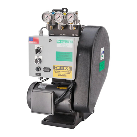
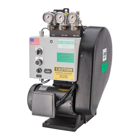
This is a 2 stage, 2 cylinder, air-cooled, oil-less compressor. This package is approximately 16
inches wide by 20.5 inches long by 29 inches tall and weighs approximately 172 lbs. See
Compressor Specifications for design operating pressures, flow rate, and gas type. Note the flow
rate will vary with the suction pressure, temperature, and compressor condition. This unit was
packaged by RIX as a ready to operate package with control and safety devices.
WARNING
Pneumatic energy hazard. Unit is designed to compress and store
high pressure gas. When pneumatic energy is released in an
uncontrolled manner, individuals may be crushed or struck by
moving machinery, equipment, or other items. If maintenance is
attempted on a pressured line without isolating the line and relieving
pressure, the sudden release of pressure can propel fittings or
rupture lines or vessels. Ensure unit is depressurized and locked out
prior to performing any maintenance.
1.3 Cooling
Due to the heat generated during compression it is necessary to cool both the compression
cylinders and the compressed gas. Cooling fans are installed to blow air over the compression
assemblies and then route the air over the cooling coils. Ambient cooling air is required to be within
the range given in Compressor Specifications. Cooler air is desirable as it will increase
compressor component life.
1.4 Gas Compression
RIX compressors are designed to safely compress gas without cylinder oil lubrication. Teflon based
piston rings are used in all stages. Since oil is not used in the compression cylinders, the
compressor will not contaminate the compressed gas; however, it is the responsibility of the user to
ensure that clean gas is supplied to the compressor suction at all times. A small amount of inert
piston ring dust will pass into the gas stream; this can be filtered out if desired.

RIX Industries MAN-2PS2B-N2 Page 2
1.5 Crankcase Lubrication
This oil-less compressor utilizes sealed bearings. Oil-less compressors contain absolutely no oil
within the whole compressor package removing the likelihood of any oil carry over, thus
eliminating contamination.

RIX Industries MAN-2PS2B-N2 Page 3
Chapter 2 – Installation
2.1 Mounting
The compressor must be firmly bolted down to a rigid foundation through all 4 mounting holes to
minimize vibration. Any allowed movement will generally increase vibration which can lead to
component damage.
2.2 Gas Plumbing
Be sure all process lines are free from contamination. Plumbing to the compressor must be sized so
that pressure at the compressor suction is within the range given in Compressor Specifications.
Discharge plumbing must be large enough to pass design flow at lowest expected back pressure
without choking the flow. User’s suction and discharge plumbing should be designed to
accommodate compressor vibration.
CAUTION
If flexible lines are used, user is responsible to secure those lines
to prevent whipping in case of breakage.
Safety relief valves are installed on the compressor at each stage of compression: suction,
interstage, and discharge. Do not start the compressor without these items properly installed. All
plumbing and components must be rated for pressures greater than the connected relief valve
setting.
Provisions must be in place to relieve all internal pressure and isolate the compressor from all
external pressure sources to ensure that the unit can be safely disassembled for maintenance. It
may be helpful to install a hand valve in the gas line downstream of the compressor to create back
pressure for testing and calibration.
DANGER
Do not install ball valves in either suction or discharge plumbing. If
closed quickly, these valves can cause explosion.

RIX Industries MAN-2PS2B-N2 Page 4
2.3 Electrical Connections
The motors and instrumentation are wired to a crankcase mounted control box. User to supply
power to the control box in accordance with the electrical requirements specified in Compressor
Specifications. All electrical connections should be made in compliance with local electrical codes.
2.4 Storage
If the compressor is taken out of service, provision should be made to protect against corrosion. At
a minimum gas suction and discharge lines should be capped and belt tension relieved. The
compressor should be rotated at least once every month. In corrosive environments, the unit
should be nitrogen purged.
After extended storage, or if stored without climate control, the compressor heads and valves
should be removed and inspected for corrosion. Bearings should also be inspected and/or replaced
and the relief valves should be cleaned, rebuilt, and/or replaced.

RIX Industries MAN-2PS2B-N2 Page 5
Chapter 3 - Start-Up & Operating Parameters
3.1 Pre-startup System Inspection
1. Visually inspect the entire system for obvious damage or leakage. Fix all issues that are
found. If major shipping damage is found contact RIX for repair or replacement parts.
2. Ensure that any safety guards are securely attached.
3. Ensure supply pressure is within the range stated in Compressor Specifications.
3.2 Start-Up
After performing the pre-startup system inspection, start the unit. When starting the compressor
for the first time or after servicing, check for leaks in the plumbing – see Section 7.2 for
recommended leak check procedure. After correcting any leaks in the system, restart the unit and
observe gas pressures and temperatures. The pressure will increase based on back pressure from
the User’s downstream plumbing. Gas temperature will also rise in conjunction with the
compression ratio of each stage.
All shutdown devices and control logic should be tested before the system is put into autonomous
operation.
3.3 Normal Operating Conditions
The table below shows theoretical operating conditions—actual pressures and temperatures may
vary. Due to the inclusion of a back-pressure regulator in the compressor package, the discharge
pressure should always be a minimum of 1500 psig. Do not adjust the back-pressure regulator
setpoint as it keeps the 2nd stage floating piston from hitting the 2nd stage valve during normal
operation.
Stage
Pressure
(psig)
Temperature
(°F)
Suction
30 - 70
70
Interstage
300-600
300
Discharge
1500-2200
225
CAUTION
Cylinder heads and discharge lines are hot. Touching any part of
the cylinder heads or discharge lines can cause burns.
It is recommended that the Service Log in the appendix of this manual be used to note operating
pressures, temperatures, and maintenance done at hours of compressor operation. If pressures do
not fall near the above stated values, or vary from your historical pressures, see Chapter 6 –
Troubleshooting for corrective action.

RIX Industries MAN-2PS2B-N2 Page 6
Chapter 4 - Control System
4.1 System Overview
This unit has an integrated control box wired for auto stop/start capability. Pressure switches
prevent the unit from operating outside of design ranges if discharge pressure rises too high or
suction pressure falls too low. The unit is also equipped with an hour meter to log cumulative run
time.
WARNING
The control box contains high voltage. Before working on electrical equipment,
take steps to ensure the system is de-energized and will remain so while work is in
progress. All circuits not known to be dead must be considered live and dangerous
at all times.
Suction pressure must be supplied to compressor before startup to keep the rod loading and/or
compression ratios within limits. Ideally the pressure in the discharge plumbing should be bled
down to the level of the suction pressure before startup. User should include provisions to allow an
unloaded start up when connecting to the compressor.
The control system is designed for two modes of operation:
1. Manual start / automatic stop
2. Auto start / stop based on both suction and discharge pressure
A HOA (Hand/Off/Auto) switch is located on the front of the control box and allows operator choice
of modes. A remote contact is installed in the control box and can tied into to an ancillary control
system for remote start/stop, signal line use, etc. If such control is desired, remove pink jumper
wired between contact blocks 1 and 3 in the control box.
4.2 Manual Operation Mode
With the selector switch in the HAND position, the compressor is in manual mode and will start
when the START pushbutton is pressed. The unit will continue to run until one of the safety
switches stops the unit. At that point the compressor will not restart until the START pushbutton is
pressed again. If any switch remains past its trip setting the compressor will not start. To manually
stop the unit, switch the HOA switch to the OFF position.
4.3 Auto Operation Mode
With the selector switch in the AUTO position the compressor will automatically start and stop
based on the signals from both the suction and discharge pressure switches. When shutdown by
either switch, the compressor will remain on standby until the pressure reverts back to the "closed"
point of the switch at which point the compressor will restart. To manually stop the unit, switch the
HOA switch to the OFF position.

RIX Industries MAN-2PS2B-N2 Page 7
4.4 Control logic Description
The following explains the logic sequence as reflected on the electrical schematic (Figure 16 in
Appendix):
1. With power applied to the unit and the HOA selector switch (HOA) in HAND, push
the START pushbutton.
2. The two pressure switches, suction (PSIL) and discharge (PSR) are connected in
series to the motor controller. If the suction pressure is high enough to close the
suction pressure switch, and the discharge switch remains closed (pressure below
the switch "closed" setting) the compressor will start.
3. Current passes through the two closed pressure switches, the closed time delay
relay (TDR), and energizes the starter coil (C-1). The starter coil starts the main
drive motor. The fan motor and hour meter also operate at this point. The green
light (LG) will energize indicating the compressor is running. Tripping of either the
suction or discharge switch will break current to the coil (TDR) which will stop the
drive motor.
4. The compressor may also be run in the automatic mode by selecting AUTO on the
HOA switch. All features are the same as described above except that after the inlet
or discharge switch shut down the unit, the compressor will automatically restart
when the switches are moved to the "closed" setting. The compressor will continue
cycling until the selector switch is moved to either HAND or OFF.
5. The unit may be stopped at any time by switching the HOA to OFF.
4.5 Safety Device Set Points
The following safety devices have been provided at the set points noted below. Pressure switch
settings may be adjusted to User’s needs but set points shall not exceed the design constraints given
in Compressor Specifications. Do not adjust relief valve settings.
Device
Stage
Set Point
Function
Relief Valve
Suction
75 psig
Relieve excess
pressure build up
Interstage
700 psig
Discharge
2200 psig
Motor Overload
N/A
Motor FLA
Shutoff
Pressure Switch
Suction
30 falling
Shutoff
Discharge
2200 rising
Shutoff

RIX Industries MAN-2PS2B-N2 Page 8
Chapter 5 - Routine Inspection & Scheduled Maintenance
5.1 Introduction
The purpose of this chapter is to provide the operator with the routine inspection and scheduled
maintenance information required to ensure a long service life of the subject compressor. RIX
recommends documenting and tracking service history using the Service Log in the appendix of
this manual.
5.2 Routine Inspection
1. Visually inspect the system for obvious damage or leakage. Fix any issues that are found.
2. Check pressures and temperatures against normal operation.
3. Check cooling air flow. Verify cooling fans blow air over the heads.
4. Inspect for loose fittings or components. Fix any issues that are found.
5. Inspect for unusual noises or vibrations.
5.3 Scheduled Maintenance
Section
Time Interval
Operation
2000
hours
3000
hours
4000
hours
Annually
5.4
Gas Filter Service
*
5.5
Compressor Valve Service
*
5.6
Running Gear Inspection
*
5.7
Piston Ring Replacement, 1
st
Stage
*
5.7
Piston Ring Replacement, 2
nd
Stage
*
5.8
Compression Cylinder Inspection
*
5.8
Instrument Calibration
*
5.9
Connecting Rod Bearings
Inspection
*
DANGER
Before performing any maintenance, the compressor power supply
should be locked Out of Service to prevent starting which could cause
injury to personnel or damage to the equipment. Relieve all internal
pressure and allow piping to cool before repair.

RIX Industries MAN-2PS2B-N2 Page 9
5.4 Gas Filter Service
Every 2000 hours of running time, the interstage and discharge filters should be inspected and
cleaned or replaced. Failure to do so at the specified interval may result in poor valve performance
or process plumbing constriction in extreme cases of filter element contamination.
5.5 Compressor Valve Service
The valves should be inspected, cleaned, and, if necessary, replaced every 4000 hours or if
pressures vary from normal, noise is detected, or abnormally high temperatures are observed.
Severe leakage will cause overheating of the suction plumbing just prior to the cylinder head.
5.6 Running Gear Inspection
All compressor running gear should be inspected every 2000 hours. Belt alignment and tension as
well as all bearings should be inspected at this time. Belt should deflect ½-¾” at the mid span with
approximately 10 lbs. force applied. Bearings should be inspected to verify smooth rotation and
adequate lubrication. At a minimum relubricate the connecting rod needle bearing after 4000 hours
of operation and replace after 8000 hours operation.
5.7 Piston Ring Replacement
Every 2000 hours the 2nd stage piston rings, expanders, and riders should be replaced and every
3000 hours the 1st stage piston rings, expanders, and riders should be replaced. As the compression
rings wear their ability to seal is diminished. Excessive wear will result in lower compressor
capacity, more frequent compressor operation, and unnecessary wear on other components. With
extreme wear the compressor will not be able to compress to the design pressure. If the
compressor starts and stops more frequently, fails to make pressure, or has degraded flow capacity,
the rings should be replaced. There is risk of damaging the cylinder liners if the rings wear out
completely.
Note: piston rings are design to seal dynamically only. Leakage in standby is normal.
5.8 Compression Cylinder Inspection
Excess piston to cylinder clearance, caused by wear to cylinder bores, will significantly decrease
ring life. Cylinder bores should be observed for wear at ring change-outs or if ring life has
significantly decreased. It is good practice to measure the diameter and surface finish of the
cylinder bores whenever the cylinders are removed or when ring life drops from normal. Maximum
wear will normally occur 1/3 to 1/2 way down the bore. A bore gauge is the best way to measure
wear. Check diameter at several depths for wash-boarding – see Section 7.10 for wear limits. Some
surface roughness is needed to allow engraining of seal material in the bore. Both cylinders should
have a surface finish of 12-16 µin Ra crosshatch. If the cylinder bore surface finish is out of
tolerance it will reduce ring life.

RIX Industries MAN-2PS2B-N2 Page 10
5.9 Connecting Rod Bearings Inspection
Every 2000 hours of running, the Connecting Rod bearings should be inspected and replaced if
necessary. To inspect the Needle Bearing (smaller), remove the Connecting Rod assembly – see
Section 7.11, inspect the Wrist Pin outer diameter for deformation, if no bumps or dents are
present, insert the Wrist Pin through the needle bearing and rotate while holding the Connecting
Rod still. Notable bumpiness, roughness, knocking, or resistance to rotation would indicate this
bearing needs to be replaced. If the Wrist Pin outer diameter contains dents or bumps, replace both
the Wrist Pin and Needle Bearing. To inspect the Ball Bearing (larger), rotate the inner race of the
bearing by hand while holding the Connecting Rod still. Like before, notable bumpiness, roughness,
knocking, or resistance to rotation would indicate this bearing needs to be replaced.
Note: if bearings are not being replaced, re-pack with (RIX P/N 45-110) Polyurea grease before
installation – see Section 7.11.
5.10 Instrument Calibration
Control instruments should be verified for accuracy annually. Pressure gauges, switches, and relief
valves can be bench tested on a hydro fixture to confirm the accuracy of each device. Use only
deionized water for these tests.

RIX Industries MAN-2PS2B-N2 Page 11
Chapter 6 - Troubleshooting
6.1 Compressor Symptoms
Abnormal compressor conditions can be evaluated more quickly and accurately by looking at
interstage pressures and temperatures. Use the table below to aid in determining the cause of any
problems with the compressor and the necessary corrective action.
Item
Symptom
Probable Causes
Corrective Action
1
Compressor stops running
before system pressure is
reached
The discharge pressure
switch is set too low
Adjust pressure switch set
point
The power source stopped
supplying power
Investigate power supply
source
The compressor has seized
Inspect compressor internal
components
2
Compressor does not reach
design flow or pressure
System plumbing is leaking
Check system for leaks
Supply pressure is too low
Adjust supply pressure to
range stated in Compressor
Specifications
Lack of back pressure in
user’s downstream piping
If downstream should be
pressurized, look for leaks in
downstream system.
If downstream should not be
pressurized, no problem.
Restricted filters or piping
Clean or replace filters and
upstream piping
Belt is loose
Inspect and tighten belt to
proper tension
Excessive piston to head
clearance
Measure and adjust piston
clearance
Piston rings are worn
Replace piston rings
Compressor valve has
failed
Replace compressor valve
3
High pressures
Restricted discharge filter
or piping
Clean filter and downstream
piping
Compressor valve has
failed
Replace compressor valve
4
Relief valve opens
High pressures were
reached
See item 3
Relief valve is set too low
Adjust relief valve set point
Relief valve has failed
Replace relief valve
5
Compressor is vibrating
excessively
Crankcase mounting bolts
are loose
Tighten crankcase mounting
bolts
Motor mounting bolts are
loose
Tighten motor mounting
bolts
Piston clearances not
properly adjusted
Measure and adjust piston
clearance

RIX Industries MAN-2PS2B-N2 Page 12
Item
Symptom
Probable Causes
Corrective Action
Mechanical failure internal
to the compressor
Inspect compressor internal
components
6
High Temperatures
Low suction pressure to
compressor
Adjust supply pressure to
range stated in Compressor
Specifications
Fans are inoperative
Repair or replace fans
High ambient temperature
Ensure ambient temperature
is within design limits
Compressor valves have
failed
Replace compressor valves
7
Loud metallic knocking
Piston is hitting valve
Measure and adjust piston
clearance
Replace back pressure
regulator
8
Ticking noise from cylinder
head
Compressor valve is worn
or broken
Replace compressor valve
This manual suits for next models
6
Table of contents
Other RIX Industries Air Compressor manuals
Popular Air Compressor manuals by other brands

Ozito
Ozito DMC-1000 instruction manual

Pentair
Pentair Hoffman VC-0916-04XH Operation and safety instructions

Air Lift
Air Lift WirelessONE 25870 installation guide
Draper
Draper DA100 instructions
Synairgy
Synairgy SACDD-24 Operation manual
Schneider Airsystems
Schneider Airsystems UNM STS 1000-10-270 XDK operating manual
California Air Tools
California Air Tools 10020CAD owner's manual
Dover
Dover PSG Mouvex Enterprise E140 Installation operation & maintenance
RIDGID
RIDGID R0230 Operator's manual
Scheppach
Scheppach HC24 Translation of original instruction manual
Sealey
Sealey SAC55075B instructions
AllTrade
AllTrade 835408 instruction manual

