Air Lift WirelessONE 25870 User manual

For maximum effectiveness and safety,
pleasereadtheseinstructionscompletely
before proceeding with installation.
Failure to read these instructions can result in an
incorrect installation.
INSTALLATION GUIDE
Kit 25870
Key Fob Activated
Compressor System
WirelessONE


TABLE OF CONTENTS
1
Introduction ....................................... 2
Important Safety Notice .............................................
Schematic Circuit Information .........................................
Installation Schematics. . . . . . . . . . . . . . . . . . . . . . . . . . . . . . 3
Electrical Schematic ................................................
...............................................4
Hardware & Tool Lists. . . . . . . . . . . . . . . . . . . . . . . . . . . . . . . 5
Installing the WirelessONE System....................6
Installing the Compressor ............................................6
Installing the Manifold ...............................................6
Installing the Harness ...............................................7
. . . . . . . . . . . . . . . . . . . . . . . . . . . . . . . . . . . . . . . . . . . . . . . 8
Checking the System. . . . . . . . . . . . . . . . . . . . . . . . . . . . . . . . . . . . . . . . . . . . . . . . 8
Operational Modes .................................8
Normal Mode......................................................8
Settings Mode .....................................................8
Saving and Recalling Memory 1 .......................................
.......................................
.......................................
How to Sync the Receiver to the Transmitter............11
How to Remove and Install the Batteries ...............11
FCC Information to User.............................11
Warranty and Returns Policy .........................12
Replacement Parts and Returns ......................13
Replacement Information ............................13
Contact Information ................................14
Templates.........................................15
Important:Avoiding Cold Weather Freeze-up............16

2MN-751
WirelessONE
Introduction
The purpose of this publication is to assist with the installation, maintenance and
troubleshooting of the WirelessONE System.
Itisimportanttoreadandunderstandtheentireinstallationguidebeforebeginninginstallation
orperforming any maintenance,serviceorrepair.The information here includesahardware
list, step-by-step installation information, safety information and a troubleshooting guide.
of this manual.
SYSTEM INFORMATION
WirelessONE is designed for automatic digital leveling of the on-board compressor system.
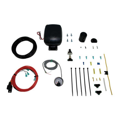
The kit includes a compressor, manifold, wiring harness, and wireless digital controller.The
system can be used in or outside the vehicle, for adjustments in full view of the vehicle.
The wireless digital controller is a compact, battery powered unit.It also includes a clip
are automatically maintained.The manifold is also weather resistant for maximum life
expectancy.
IMPORTANT SAFETY NOTICE
of the vehicle.Check your vehicle’s owner’s manual and do not exceed the maximum load
listed for your vehicle.
Gross Vehicle Weight Rating: The maximum allowable weight of the fully loaded vehicle
Payload: Thecombined, maximum allowableweightof cargo andpassengersthatthe truck
SCHEMATIC CIRCUIT INFORMATION
Example:
Circuit
Number
Wire
Color
Wire
Size
Circuit
Function
(1st & Last Letter)

3
MN-751
WirelessONE
Installation - Electrical Schematic
g. 1

4MN-751
WirelessONE
Installation - Pneumatic Schematic
g. 2

5
MN-751
WirelessONE
TOOLS LIST
Description..............................................Qty
................................................1
Safety stands........................................................
Safety glasses...................................................... 1
Heavy duty drill.....................................................1
..............................................1
Description..............................................Qty
...............................................1
............................................................1
Hose cutter........................................................... 1
Spray bottle with dish soap/water solution ........... 1
...................................................1
HARDWARE LIST
STOP!
Item Part # Description................................Qty
...............................................1
................................1
........................................1
..................................1
..................1
Hardware Pack
.......................................1
..........................1
................................1
.....................1
Item Part # Description................................Qty
..........................1
.............................1
.........................1
....................1
........................1
.............................................5
......
..................................
................................................1
.....
6MN-751
WirelessONE
INSTALLING THE COMPRESSOR
Select a rigid mounting location for the compressor on the vehicles frame or cross1.
The electrical harness will force the compressor to be within 24” of the manifold in order to
make electrical connections.
Use the supplied self tapping fasteners to fasten the compressor to the frame or cross member.
Oneoftheselftapping screws will be used as anelectricalgroundforthecompressor and manifold ring terminals.
INSTALLING THE MANIFOLD
1.
Compressor
Frame
Relay
Harness Ground
Compressor Ground
Self-tapping
Screws
g. 3
Installing the WirelessONE System
NOTE
g. 4 g. 5

7
MN-751
WirelessONE
INSTALLING THE HARNESS
1.
a. Cut off terminal on compressor red wire.
e. Heat buttsplice to seal connection.
f. Connect compressor ground wire ring terminal, harness ground wire ring terminal,
•Using one of the self tapping screws for the compressor you can attach
all the components to the vehicle frame ground.
•Cut off the excess wire length if all is not needed.
g. 6

8MN-751
WirelessONE
•Heat buttsplice to seal connection.
f. Crimp on the correct terminal that mates with the appropriate type of fuse tap in
terminal for your application.
ATTACHING THE AIR LINES
Manifold to Compressor:
compressor.
Manifold to “T-Fitting”:
“T-Fitting” to Springs:
CHECKING THE SYSTEM
connection. Repair and replace as necessary.
OPERATIONAL MODES
Normal Mode :Mode in whichtheuser can incrementanddecrement the desiredpressure,
g. 7
Adapter #1
Adapter #2 *
Adapter
Fuse
* Uses 3/16 (smaller) Female Push On Connector

9
MN-751
WirelessONE
when the battery is getting low.
Settings Mode: Mode in which the user can change the backlighting color, alter the unit
Settings Mode
1.
options.
4.
5.
Normal Mode
Increasing desired pressure:
1. Initial press of any button will wake up display and not perform any function.
depending on the unit of measure selected.
When the user releases the button the new desired pressure will be transmitted to the receiver.
depending on the unit of measure selected.
When the user releases the button the new desired pressure will be transmitted to the receiver.
If desired pressure is max pressure then pressing the Up arrow will result in no function.
Decreasing desired pressure:
1. Initial press of any button will wake up display and not perform any function.
g. 8
Internal Clips
Internal Clips
M2
M1

10 MN-751
WirelessONE
depending on the unit of measure selected.
When the user releases the button the new desired pressure will be transmitted to the receiver.
depending on the unit of measure selected.
When the user releases the button the new desired pressure will be transmitted to the receiver.
in no function.
Saving and Recalling Memory 1:
Recalling Memory
Initial press of any button will wake up display and not perform any function.
Once the button is released the display will display the new desired pressure and transmit the desired pressure to the receiver.
Saving to Memory
seconds to set the desired pressure to memory 1.
times.
Saving and Recalling Memory 2:
Recalling Memory
Initial press of any button will wake up display and not perform any function.
Once the button is released the display will display the new desired pressure and transmit the desired pressure to the receiver.
Saving to Memory
times.
Saving and Recalling Memory 3:
Recalling Memory
Initial press of any button will wake up display and not perform any function.

11
MN-751
WirelessONE
Once the buttons are released the display will display the new desired pressure
Saving to Memory
times.
HOW TO SYNC THE RECEIVER TO THE TRANSMITTER
(ONLY NEEDED WITH A REPLACEMENT TRANSMITTER)
Turn ignition on.1.
It will be the yellow wire that is looped with heat shrink around it.
Touch this wire to the self tapping screw that you have used for grounding your receiver4. / compressor.
5. Unplug the connector on the top.
Connect power to the receiver while grounding the sync input.6.
7.
the receiver.
Oncethe receiver hasreceiveda message itwillsync with thattransmitterand stop clicking the solenoid in 1 second intervals.
HOW TO REMOVE AND INSTALL THE BATTERIES
FCC INFORMATION TO USER
NOTE:
FCC ID: YHT-BRM920AJM1017

12 MN-751
WirelessONE
Air Lift 1000....................Lifetime Limited
RideControl....................Lifetime Limited
SlamAir...........................Lifetime Limited
LoadLifter 5000*.............Lifetime Limited
LifeStyle**..........................1 Year Limited
Load Controller (I) ............2 Year Limited
Load Controller (II) ...........2 Year Limited
SmartAir ............................2 Year Limited
Wireless AIR......................2 Year Limited
Other Accessories............2 Year Limited
*formerly SuperDuty
**formerly EasyStreet
retail purchaser against manufacturing defects when used on catalog-listed applications on
cars, vans, light trucks and motorhomes under normal operating conditions for as long as
improperly applied, improperly installed, used in racing or off-road applications, used for
commercial purposes, or which have not been maintained in accordance with installation
instructions furnished with all products.The consumer will be responsible for removing
Removal of the manifold cover voids Air Lift warranty.
loss of use of the product, loss of time, inconvenience, commercial loss or consequential
product without assuming any obligation to modify any product previously manufactured.
This warranty gives you specific legal rights and you may also have other rights that vary
from state-to-state.Some states do not allow limitations on how long an implied warranty
lasts or allow the exclusion or limitation of incidental or consequential damages.The above
limitation or exclusion may not apply to you.There are no warranties, expressed or implied
warranty period.There are no warranties that extend beyond the description on the face
Warranty and Returns Policy

13
MN-751
WirelessONE
Missing or damaged item?
please gather the following information:
purchased it
damaged item
Number 57215
Gross Wt. 18.280 lb
656952557244
TEAM
02/07/05
57215
1
Help us avoid waste and order by part number. If you need an air spring
replacement part, please follow these steps.
www.airliftcompany.com/downloads.html.
you the part you need, the same day, in the U.S. or Canada.
Please do not cannibalize
kits for parts!
Step 1
Step 2
Replacement Information
Contact Air Lift Company customer service at (800) 248-0892 fi rst if:
Contact the retailer where the kit was purchased:
Replacement Parts and Returns

14 MN-751
WirelessONE
Contact Information
Ifyouhaveanyquestions,commentsorneedtechnicalassistancecontactourcustomerservice
www.airliftcompany.com.
It's easy to put your air springs to work
with an Air Lift on board air compressor system!
Save time and money! Register your warranty online today at
www.airliftcompany.com/warrantyreg.htm
ensuring that you have the best possible experience with our products. If you have any questions,
concernsorevenasuggestion,pleasefeelfreetocontactus.Ourcustomerservicerepresentatives
arehereforyouMondaythroughFriday,8a.m.to7p.m.EasternTime.Needhelpsoonerthanthat?
Check out the wealth of information that we have online for you at www.airliftcompany.com.
Choose the best option for your ride from many models and features!
Since
1949
®

15
MN-751
WirelessONE
Templates
USE 732 DRILL TO
CREATE HOLE
USE 732 DRILL TO
CREATE HOLE
HOLE PATTERN FOR
BOTTOM OF MANIFOLD
HOLE PATTERN FOR
SIDE OF MANIFOLD
2.1000
0.6300
16060 COMPRESSOR
8.0000
2.0000
USE 1/4" DRILL TO
CREATE HOLE
HOLE PATTERN FOR
BOTTOM OF
COMPRESSOR
USE 732 DRILL TO
CREATE HOLE
USE 732 DRILL TO
CREATE HOLE
HOLE PATTERN FOR
BOTTOM OF MANIFOLD
HOLE PATTERN FOR
SIDE OF MANIFOLD
2.1000
0.6300
16060 COMPRESSOR
8.0000
2.0000
USE 1/4" DRILL TO
CREATE HOLE
HOLE PATTERN FOR
BOTTOM OF
COMPRESSOR
1.25
HOLE PATTERN FOR
BRACKET (11068)

16 MN-751
WirelessONE
IMPORTANT: To Avoid Cold Weather Freeze-up
Add 4 oz.(1/2 cup) of
“GUNK” Brand AIR BRAKE ANTI FREEZE
purchased at an automotive parts store or truck supply store.
WARNING:
CAUTION:
1/2 Cup
Pour Here


Thank you for purchasing Air Lift products — the professional installer’s choice!
Need Help?
Contact our customer service department by calling
Register your warranty online at
www.airliftcompany.com/warrantyreg.htm
Other manuals for WirelessONE 25870
3
Table of contents
Other Air Lift Air Compressor manuals

Air Lift
Air Lift QuickShot 25690 User manual

Air Lift
Air Lift WirelessONE 25870 User manual

Air Lift
Air Lift Ride Control 59516 User manual

Air Lift
Air Lift 72000 User manual

Air Lift
Air Lift LoadCONTROLLER/Dual 25852 User manual

Air Lift
Air Lift Load Controller I User manual

Air Lift
Air Lift WirelessONE 25870 User manual

Air Lift
Air Lift LoadController 25850 User manual

Air Lift
Air Lift WirelessONE 25870 User manual

Air Lift
Air Lift QuickSHOT 25572 User manual