2/19
NT 208-A00 03 23 Enterprise e
MOUVEX ROTARY VANE COMPRESSORS
INSTALLATION, OPERATION, AND MAINTENANCE INSTRUCTIONS
MODELS : E140 - E170
SAFETY DATA
ENTERPRISE compressors MUST only be installed in sys-
tems which have been designed by qualified engineering
personnel. The system MUST conform to all applicable local
and national regulations and safety standards.
This manual is intended to assist in the installation and oper-
ation of the ENTERPRISE compressors, and MUST be kept
with the compressor.
ENTERPRISE compressor service and maintenance shall
be performed by qualified technicians ONLY. Service and
maintenance shall conform to all applicable local and nation-
al regulations and safety standards.
Thoroughly review this manual, all instructions and hazard
warnings, BEFORE performing any service or maintenance
on the ENTERPRISE compressors.
Maintain ALL system and ENTERPRISE compressor opera-
tion and hazard warning decals.
NOTE :
Numbers in parentheses following parts indicate refe-
rence numbers on the ENTERPRISE Rotary Vane
Compressor Parts List 208-A01.
TABLE OF CONTENTS Page
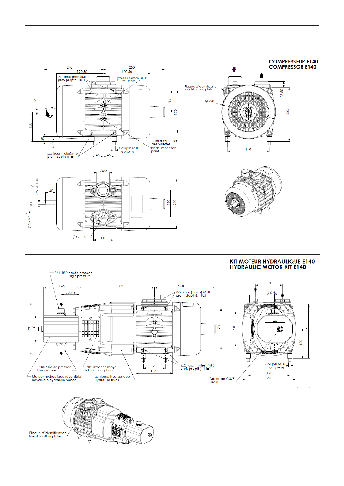
1. OVERALL DIMENSIONS . . . . . . . . . . . . . . . . . . . . . . . . . .4
1.1 E140 . . . . . . . . . . . . . . . . . . . . . . . . . . . . . . . . . . . . . . .4
1.2 E170 . . . . . . . . . . . . . . . . . . . . . . . . . . . . . . . . . . . . . . .5
2. TECHNICAL DATA . . . . . . . . . . . . . . . . . . . . . . . . . . . . . .6
3. INSTALLATION . . . . . . . . . . . . . . . . . . . . . . . . . . . . . . . . .6
3.1 Compressor mounting . . . . . . . . . . . . . . . . . . . . . . . . . .6
3.2 Drive systems . . . . . . . . . . . . . . . . . . . . . . . . . . . . . . . .7
3.3 Drive shaft - See Figure 5 . . . . . . . . . . . . . . . . . . . . . . .8
3.4 Hydraulic drive . . . . . . . . . . . . . . . . . . . . . . . . . . . . . . .8
3.5 Piping . . . . . . . . . . . . . . . . . . . . . . . . . . . . . . . . . . . . . .9
4. USE . . . . . . . . . . . . . . . . . . . . . . . . . . . . . . . . . . . . . . . . .11
4.1 Starting-up . . . . . . . . . . . . . . . . . . . . . . . . . . . . . . . . . .11
5. MAINTENANCE . . . . . . . . . . . . . . . . . . . . . . . . . . . . . . . .12
5.1 Maintenance schedules . . . . . . . . . . . . . . . . . . . . . . .12
5.2 Quick blade inspection (E140 only) . . . . . . . . . . . . . .13
5.3 Sideplate removal . . . . . . . . . . . . . . . . . . . . . . . . . . . .13
5.4 Blade removal and inspection . . . . . . . . . . . . . . . . . . .14
5.5 Rotor inspection . . . . . . . . . . . . . . . . . . . . . . . . . . . . .14
5.6 Sideplate disassembly . . . . . . . . . . . . . . . . . . . . . . . .15
5.7 Sideplate assembly . . . . . . . . . . . . . . . . . . . . . . . . . . .15
5.8 Setting sideplate clearance . . . . . . . . . . . . . . . . . . . . .16
5.9 Compressor assembly . . . . . . . . . . . . . . . . . . . . . . . .17
5.10 Initial start up / Reinstallation . . . . . . . . . . . . . . . . . .18
6. TROUBLESHOOTING . . . . . . . . . . . . . . . . . . . . . . . . . . .18
7. SCRAPPING . . . . . . . . . . . . . . . . . . . . . . . . . . . . . . . . . .18
8. COMPRESSORS FORM INFORMATION . . . . . . . . . . . . .19
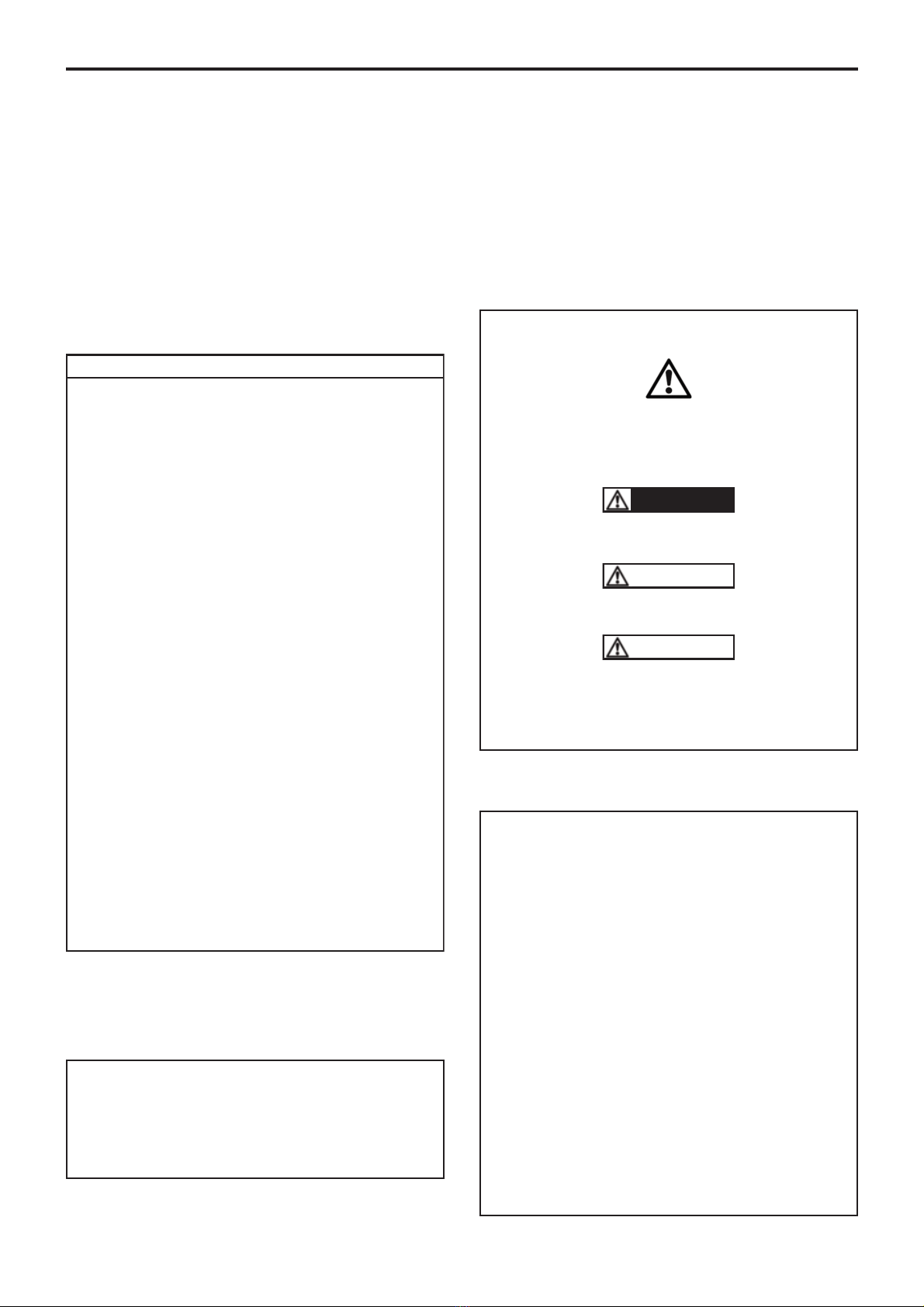
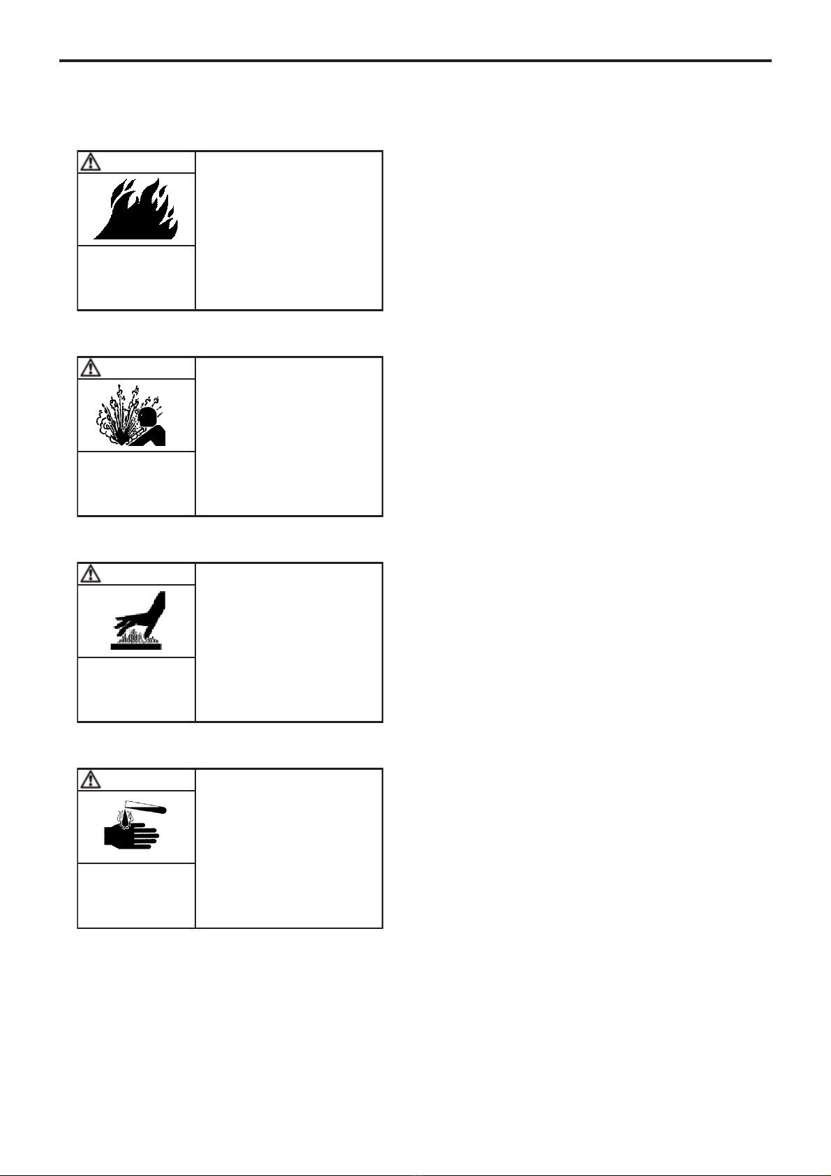
Definition of safety symbols
This is a SAFETY ALERT SYMBOL.
When you see this symbol on the product, or in the manual,
look for one of the following signal words and be alert to the
potential for personal injury, death or major property damage.
Warns of hazards that WILL cause serious personal injury,
death or major property damage.
Warns of hazards that CAN cause serious personal injury,
death or major property damage.
Warns of hazards that CAN cause personal injury or property
damage.
NOTICE
Indicates special instructions which are very important and
must be followed.
DANGER
WARNING
CAUTION