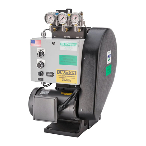
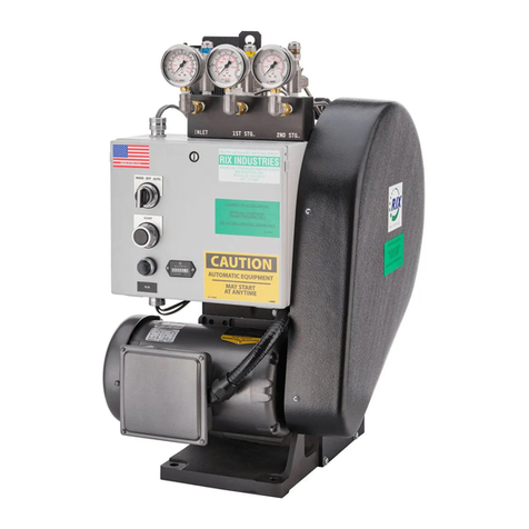
RIX Industries SA-6B Series User manual

O
OP
PE
ER
RA
AT
TI
IN
NG
G
I
IN
NS
ST
TR
RU
UC
CT
TI
IO
ON
NS
S
a
an
nd
d
P
PA
AR
RT
TS
S
L
LI
IS
ST
T
f
fo
or
r
RIX AIR COMPRESSOR
MODEL SA-6B*
WARNING
This compressor is designed for compressing ambient air only and is not suitable
for compressing oxygen, oxygen enriched air, or oxygen enriched gases.
*See Serial Number Page for applicable serial numbers.
Rev. 5/16

i
TABLE OF CONTENTS
PART I
Chapter Page
TABLE OF CONTENTS.......................................i, ii
SERIAL NUMBER PAGE ......................................iii
SAFETY PRECAUTIONS ......................................iv
RELIABILITY DO'S AND DONT'S........................v
WARRANTY...........................................................vi
Chapter Page
1. GENERAL INFORMATION .........................1-1
1.1 Safety Precautions.....................................1-1
1.2 Introduction...............................................1-2
1.3 Equipment Description.............................. 1-2
2. OPERATION....................................................2-1
2.1 Introduction...............................................2-1
2.2 Controls & Indicators
Common to All Compressors ................ 2-1
2.3 Controls & Indicators on
Gasoline Engine Driven Compressors...2-4
2.4 Controls & Indicators on
Electric Motor Driven Compressors......2-5
2.5 Deleted
2.6 Operating Procedures................................ 2-7
2.6.2 Gasoline Engine Drive Operation.............2-7
2.6.3 Electric Motor Drive Operation..............2-11
3. FUNCTIONAL DESCRIPTION....................3-1
3.1 Introduction...............................................3-1
3.2 Mechanical................................................ 3-1
3.3 Air Flow System .......................................3-1
Chapter Page
4. SCHEDULED MAINTENANCE .......................4-1
4.1 Introduction...................................................4-1
4.2 Engine Oil Level (Gasoline) .........................4-1
4.3 Engine Oil Change (Gasoline)......................4-1
4.4 Engine Air Cleaner (Gasoline)......................4-3
4.5 Rod End Bearings & Thrust Riders ..............4-3
4.6 General Inspection ........................................4-5
4.7 Compressor Ball Bearings.............................4-5
4.8 Fuel Line (Gasoline) .....................................4-5
5. COMPRESSOR TROUBLESHOOTING .........5-1
5.1 General..........................................................5-1
6. CORRECTIVE MAINTENANCE.....................6-1
6.1 Introduction...................................................6-1
6.2 Adjustments & Alignments...........................6-1
6.3 Assembly Techniques ...................................6-2
6.4 Repair of Assemblies & Sub-Assemblies .....6-4
7. PARTS LIST.........................................................7-1
7.1 Introduction...................................................7-1
LIST OF TABLES
Table Title Page
1-1 Reference Data .................................................1-3
1-2a Gasoline Engine Drive Package ....................... 1-4
1-2b Electric Motor Drive Package ..........................1-4
2-1a Simplified Start-up Check List, Gasoline.......2-10
2-1b Simplified Start-up Check List, Electric......... 2-12
4-1 Scheduled Maintenance....................................4-1
4-2 Oil Grade Selection Chart.................................4-3
5-1 Compressor Troubleshooting ...........................5-1
Table Title Page
6-1 Tolerances on Wearing Parts............................6-8
6-2 Torque Chart.....................................................6-9
7-1 Parts List, Compressor Cross Section...............7-1
7-2 Parts List, Moisture Separators.........................7-6
7-2a Relief Valve, 3rd Stage.....................................7-6
7-3 Parts List, Gasoline Engine Drive.....................7-7
7-4 Parts List, Electric Motor Drive......................7-10
7-5 Recommended Spare Parts & Tools ...............7-13

ii
PART 1 (Continued)
LIST OF FIGURES
Figure Title Page
2-1 Compressor Layout......................................... 2-2
2-1a Wiring for Optional Pressure Switch
Used with Gasoline Engine Drive...............2-3
2-2 Electrical Schematic, 208-240VAC 3 Phs......2-6
2-2a Electrical Schematic, 440-480VAC 3 Phs......2-6a
2-2b Electrical Schematic, 208-240 VAC, 1 Phs....2-6b
2-2c Electrical Schematic, 380VAC 3Phs..............2-6c
2-3 Fuel System ....................................................2-9
2-3a Fuel Pump Assembly......................................2-9a
3-1 Mechanical Drive Schematic..........................3-3
3-2 Air Flow Diagram...........................................3-4
4-1 Maintenance Points.........................................4-2
4-2 Engine Air Cleaner.........................................4-4
6-1 Tension Check, Drive Belt .............................6-1
6-2 Alignment Check............................................6-1
Figure Title Page
6-3 Thrust Plate Alignment...................................6-3
6-4 Piston Details..................................................6-5
7-1a Compressor Cross Section............................7-14
7-1b Compressor Cross Section (cont'd)...............7-15
7-1c Cylinder Head & Valve Details ...................7-16
7-1d Rod End Bearing Assemblies.......................7-16
7-2 Moisture Separator Assemblies ....................7-17
7-3 Compressor Assembly,
Gasoline Engine Drive..............................7-18
7-4a Compressor Assembly,
Electric Motor Drive .................................7-19
7-4b Compressor Assembly,
Electric Motor Drive (cont'd)....................7-20
TABLE OF CONTENTS
PART II
BACK PRESSURE REGULATOR...............................................................................DWG. A4731
MAINTENANCE ASSISTANCE KIT FOR SA-6B.....................................................DWG. A8139

iii
SERIAL NUMBER PAGE
RIX MODEL SA-6B
This manual is applicable to all RIX Industries
Model SA-6B Air Compressors bearing
one of the following Serial Numbers.
7900 – 7923, 8111 - 8135
8300 – 8333, 8415 - 8464
8664 – 8708, 8873 - 8890
8948 – 8997, 9105 - 9154
9213 – 9262, 9650 – 9700
9731 – 9779, 10079 – 10082
10133 – 10142, 10216 – 10223
10239 – 10252, 10306 – 10313
10349 – 10358, 10548 – 10557
10664 AND ABOVE

iv
SAFETY PRECAUTIONS
WARNING
A high pressure vessel is a concentrated
energy source which could release
explosively.
Very special care must be exercised while filling SCUBA tanks or other high pressure containers.
The pressure vessel should be placed behind a barricade which will shield personnel from injury in
the event the vessel should rupture. When filling SCUBA tanks, submerging the cylinder in water
also helps to reduce the temperature created in the filling process as well as reduce the chance of
injury from an explosion.
The RIX Model SA Compressor is equipped at the factory with a final discharge safety valve set at
3600 or 4000 psig. Optional higher pressure set pointsafety valves are available at 4500 psig and
5000 psig. Trained personnel with the proper tools can adjust the safety valve to a lower pressure.
Also available is RIX Pressure Switch, Part No. A76-191, which is manually adjustable and designed
to operate at pressures from approximately 1500 psig up to 4500 psig.
CAUTION
The system pressure must be relieved
before adjusting the pressure switch.
Adjusting the pressure switch while
under pressure will damage the switch.
Malfunction of this switch combined
with malfunction of the safety valve
could haveserious results.
Do not depend on the safety valve and
pressure switch to control the high
pressure air supply.
All self-contained breathing apparatus back-pack tanks are stamped with the design pressure and
dated. These values should not be exceeded. A reliable pressure gauge which has been recently
checked against another known accurate pressure gauge must be connected in the filler line. This
gaugemust be continuously observed during the filling operation ofthe pressure vessel
.

A7035
v
SA COMPRESSOR RELIABILITY DO's & DON'T's
DO's
DO grease the rod end bearings and thrust rider every 25 hours of operation or every three (3) months.
DO drain moisture separators every 10 minutes or more often as needed in a high humidity climate.
WARNING
Failure to properly drain the moisture seperators could result in water carry over and possible
damageto the compressor.
DO make sure dryer cartridge is pushed firmly into place before installing the top cylinder cap. Otherwise,
leakage will occur through hole in bottom of the housing. Remove plastic caps from both
ends of the
dryer cartridge before installing.
NOTE: Installation of a spring on the top of the cap may be required to secure the cartridge on
the nipple housing.
NOTE: The cartridge has a 4-year shelf life if left unopened.
DON'T's
DON'T operate without the back pressure regulator (BPR) installed. It must be located either directly at the
compressor outlet and
(if applicable) after the dryer cylinder as factory installed on "option packages."
The compressor requires back pressure to hold the floating 3rd stage piston tightly against the piston rod
(approximately 1500 psig).
DON'T drain the pressure from the dryer cylinder except when replacing the cartridge.
DON'T adjust the pressure switch (except the Murphy Switchgage on Option Package 3) unless all compressor
pressure is bled off.
DON'T use any grease other than that designated in paragraph 4.5.2 in your manual when lubricating the rods
and thrust rider. This is a special teflon resin lubricant designed for sustained high pressure operation.
Substitute greases will reduce rod life.
DON'T operate the unit with main shaft counterweight(s) left off or installed out of phase. See Figure 7-1a.
DON'T operate unit in reverse rotation. See Figure 3-1.
DON'T operate without cooling shroud in place.
WARNING
This compressor is designed for compressing ambient air only and is not suitable for
compressing oxygen, oxygen enriched air, or oxygen enriched gases.

vi
RIX INDUSTRIES'
SA COMPRESSOR WARRANTY
RIX Industries warrants all SA compressors as follows:
Every RIX compressor is carefully inspected, assembled and thoroughly tested before
shipment is made from the factory and each new compressor sold by RIX Industries is warranted to
be free from defect in material and workmanship for a period of six (6) months from the date of
shipment for the SA compressors.
The obligation under this warranty, statutory or otherwise, is limited to the replacement of
repair at the Manufacturer's factory, or at a point designated by the Manufacturer, of such part as
shall appear to the manufacturer, upon inspection at such point, to have been defective in material or
workmanship.
This warranty shall not apply to any compressor which has been subject to misuse, neglect,
or accident, nor shall it apply to any machine upon which repairs or alterations have been made
unless authorized by the Manufacturer.
RIX Industries makes no warranty in respect to accessories such as electric motors and/or
gasoline engines powering the compressor, or to controls such as pressure switches, solenoid valves
and motor starters, such being subject to the warranties of their respective manufacturers.
The Manufacturer shall in no event be liable for consequential damages or contingent
liabilities arising out of the failure of any compressor or parts to operate properly.
No express, implied or statutory warranty other than herein set forth is made, or authorized
to be made, by the Manufacturer.

1-
1
CHAPTER 1
GENERAL INFORMATION
AND SAFETY PRECAUTIONS
1.1 SAFETY PRECAUTIONS
1.1.1 GENERAL. To insure the safe operation of this equipment, the operator must:
a. Follow the instructions in the manual for starting, stopping, and maintaining the
compressor.
b. Locate the compressor inlet where the air is pure, away from exhausts or other
harmful gasses.
c. Never remove safety guards.
d. Never operate if a safety valve is popping.
e. Never operate with a safety valve removed or adjusted to a pressure other than the
factory recommendation.
f. Never fill any receiver pressure vessel, or SCUBA tank above its safe working limit.
Make sure the vessel being filled has been inspected, hydrostatically tested, and
certified as approved for service.
g. Never operate the equipment if there is an indication of improper operation, air leaks,
unusual noise, or broken or loose parts.
h. Never work on the equipment without first relieving all pressure, de-energizing the
unit and tagging it out. Always protect eyes and face when opening valves to bleed
off pressure. FOR ENGINE DRIVEN UNITS
i. To prevent getting shocked, do not touch the spark plug or spark plug wire while the
unit is running.
j. To prevent getting burned, stay clear of the exhaust muffler and all other hot areas of
the engine.
k. Handle gasoline in a safe manner. Never use near an open fire or flame. Keep tank
and fuel line away from hot exhaust.
FOR ELECTRIC MOTOR DRIVEN UNITS
l. Make sure ON/OFF switch is in sight of the compressor and gauges are easily
accessible. (When remotely located.)
m. Make sure electrical connections are made in the approved manner and that the unit is
properly grounded.
n. Make sure the electrical service is rated and properly fused for the current rating of
the motor.

1-
2
1.2 INTRODUCTION
1.2.1 PURPOSE AND SCOPE. The purpose of this manual is to provide all information
pertinent to the operation and maintenance of the RIX Model SA-6B high pressure,
oil free, air compressor. This publication sets forth requirements and procedures for
safe operation and servicing, and includes descriptive data and tests necessary to
achieve a functional understanding of the compressor.
The compressor is supplied as a bare pump or a package with an electric motor or
gasoline engine drive. This manual covers all the available systems in the general
text and gives specific details in subsections for each type of drive package.
This publication represents the sole authority for the subject equipment.
1.2.2. APPLICABILITY. This manual is applicable to all air compressors bearing the RIX
Industries Model Number SA-6B (1S3B-6) and identified by the serial numbers
shown on the Serial Number page.
1.3 EQUIPMENT DESCRIPTION
1.3.1 GENERAL. The RIX SA-6B Compressor is a lightweight, portable air compressor
package suitable for filling SCUBA (Self Contained Underwater Breathing
Apparatus) cylinders to 3000 psi. The compressor is used for alternate applications
where there is a requirement for reliable service and pure compression of air. The
most common is for filling portable breathing systems (up to 4500 psi) for Fire
Departments and Rescue Teams.
The main text of the manual describes the SCUBA filling operation but the
information is applicable to filling any approved high pressure receiver.
The driver and compressor are coupled by a V-belt pulley drive and mounted on a
frame.
The compressor is a three stage, reciprocating air pump using an axial piston drive.
All bearings are sealed and the piston rings are a filled PTFE plastic. No oil is used
during the compression process, thereby eliminating the possibility of introducing
carbon monoxide or other harmful contaminants into the air stream. It is still critically
important to locate the air inlet upwind and as far as possible from the engine exhaust
or any other sources of contaminated air.
The compressor is furnished with interstage and final moisture separators to remove
condensed water. Screen filters in the separators trap particulate contaminant to 25
micron in size.
Pressure relief valves are located after each stage to prevent over pressurization of the
system. An optional high pressure shutdown switch is available to automatically shut
the compressor down when the pressure reaches the high pressure shutdown preset
set point of the switch.

1-
3
TABLE 1-1
Reference Data
Descriptive Data
RIX Industries Model SA-6B oil free, three stage, axial piston,
portable air compressor package.
Functional
Power required: 5.0 brake horsepower (5.0) HP electric motor or
8.0 HP gas engine recommended.)
Pressure: 3600 psi maximum (standard relief valve setting)
(4500 & 5000 psi available)
Normal operating pressure in relation to a final dis-
charge pressure of the compressor is as follows (in
psi):
1st Stage 80-90 90-100
2nd Stage 450-500 550-620
3rd Stage 3300 4500
Capacity: 5.5 Standard Cubic Feet per minute.
Speed: 1500 RPM at Compressor.
Capabilities &
Limitations
Air cooled and frame mounted for portable or permanent mounting.
Self lubricated pistons for oil free compression.
Environmental
Characteristic
Designed to operate at ambient temperatures up to 120˚F and relative
humidities to 90 percent. All components are anodized, plated, or
painted to resist corrosion.
Compressor Piston Size: 1st Stage: 3.0" Dia.
2nd Stage: 1.25" Dia.
3rd Stage: .56" Dia.
Stroke: 1.25"
Cooling Forced air fan
Compression type Oil free

1-
4
TABLE 1-2a
GASOLINE ENGINE DRIVE PACKAGE
Equipment, Accessories and Documents Supplied (Std.)
OVERALL
QTY. ITEM NAME DIMENSIONS WEIGHT
1 ea. RIX Model SA-6B with Wisconsin Engine 33"L x 19"W x 18"H 150 Lbs.
or
1 ea. RIX Model SA-6B with Honda Engine 35"L x 19"W x 19"H 155 Lbs.
1 ea. Gasoline Tank & Fuel Hose 21"L x 13"W x 9"H 6 Lbs. (Empty)
6 Gallons
1 ea. Suction Hose (for remote intake) with Filter 15 ft. long x 1" Dia. 3 1/2 Lbs.
1 ea. Technical Manual 8-1/2 x 11” x 1/2” 1 Lb.
TABLE 1-2b
ELECTRIC MOTOR DRIVE PACKAGE
Equipment, Accessories and Documents Supplied (Std.)
OVERALL
QTY. ITEM NAME DIMENSIONS WEIGHT
1 ea. RIX Model SA-6B with 230/460/3/60 Motor 30"L x 18"W x 18"H 180 Lbs.
or
1 ea. RIX Model SA-6B with 230/1/60 Motor 30"L x 18"W x 18"H 205 Lbs.
or
1 ea. RIX Model SA-6B with 380/3/50 Motor 30”L x 18”W x 18”H 180 Lbs.
1 ea. Magnetic Starter 9-3/4” x 6-1/2” x 4-1/2” 8-1/2 Lbs.
1 ea. Technical Manual 8-1/2 x 11” x 1/2” 1 Lb.

2-1
CHAPTER 2
OPERATION
2.1 INTRODUCTION
2.1.1 GENERAL. Figure 2-1 shows the layout of the compressors, including all controls
and indicators. The operator should be familiar with all controls and safety features
prior to initial start-up.
The operation of each packaged system, gas and electric, is covered in separate
section of this chapter. Ignore those sections that do not apply to the equipment being
used.
The first section of this chapter describes controls and indicators followed by detailed
operating procedures. For convenience, quick reference tables are provided on each
start-up procedure.
2.2 CONTROLS AND INDICATORS COMMON TO ALL COMPRESSORS
2.2.1 FILLING HOSE. A variety of fill hoses and tank adapters are available from Rix.
The yoke has a pressure bleed screw to relieve pressure when disconnecting.
Mounted to the yoke is a pressure gauge. The gauge measures pressure in the cylinder.
2.2.2 MOISTURE SEPARATOR DRAIN VALVES. Centrifugal type moisture separators
are located between the second and third stages and at the final discharge. Each is
provided with a drain valve. These are used for draining accumulated condensate and
relieving all pressure when servicing. The moisture separator should be drained
every half hour of use.
2.2.3 PRESSURE RELIEF VALVES. The compressor is protected from over
pressurization by relief valves located after each stage. The standard final relief valve
is set for 3600 psi. Care must be used when filling SCUBA cylinders rated for only
2250 psi.
DANGER
The operator must be sure that the cylinder is not filled higher than its certified
pressure rating Failure to do so could result in catastrophic failure of the
cylinder.
Make sure SCUBA cylinder being filled is fitted with a valve having a blowout disc
as an added safety measure.
2.2.4 PRESSURE CONTROL SWITCH. A high pressure shutdown switch is available for
mounting on electric and gasoline engine driven compressors. This can be set to shut
the compressor down when the discharge pressure reaches the set point of the switch.
The high pressure shutdown switch is adjustable in the range of 1500 to 4500 psi.
The switch, when provided, is set at the factory to 3000 psig or at the pressure
specified by the customer and tagged with the set pressure. This pressure switch is
manually adjustable to accommodate a wide range of discharge pressures.

WISCONSON 7.5 HP
MODELS ONLY
(OPTIONAL)
STARTER BOX
2ND & 3RD
STAGES
2ND & 3RD
STAGES
OPPOSITE SIDE
(NOT SHOWN)
HIGH PRESSURE
(OPTIONAL)


2-4
NOTE
Care must be exercised to adjust the pressure setting of the switch only when the
compressor is turned off and with pressure relieved from the discharge line.
Attempting to reset the switch while under pressure can damage the threads of the
adjustment mechanism and may require replacement of the switch.
To set the switch at the desired shutoff pressure, rotate the adjustment screw at the top
of the switch counter-clockwise to an arbitrary low pressure setting. Start the
compressor and observe the discharge pressure at which the switch is actuated,
stopping the compressor. Relieve the discharge pressure. Reset the switch by turning
the screw clockwise and restart the compressor. Repeating this procedure will
gradually increase the switch set point to the desired shutdown pressure.
It is of critical importance for the operator to be able to determine the safe working
pressure of the SCUBA cylinder to be filled and not to exceed that pressure when
filling. If in doubt, consult a local dive shop or call the Department of Transportation
regarding SCUBA cylinder ratings.
Recommended wiring instructions for the pressure control switch are found on pages
2-6 to 2-6b for electric motor driven compressors.
NOTE:
Pressure switch adjustment can only be made when pressure is relieved. DO
NOT ATTEMPT TO ADJUST SWITCH WITH PLIERS!
2.3 CONTROLS AND INDICATORS ON GASOLINE ENGINE DRIVEN
COMPRESSORS (See separate Wisconsin or Honda engine manual)
(Gasoline)
2.3.1
(Gasoline)
FUEL SYSTEM. The fuel system consists of six gallon gas tank, disconnectable fuel
line, fuel pump and filter, carburetor, and throttle control.
2.3.1.1
(Gasoline)
GASOLINE TANK. The gas tank has a fuel level indicator incorporated in the
screw-
on cap. At the top of the cap is a small vent screw which should be backed off
(counterclockwise) to allow venting while the engine is running. During trans
-
portation, this vent should be closed to avoid spillage.
The base of the fuel tank has a molded divider which acts as a reserve. Momentarily
tipping the tank will allow the reserve gas to flow ov
er the divider so that it can be
utilized.
This is a four cycle engine designed to use only regular grade gasoline. Do not use
two cycle outboard gasoline or any oil/gas mixture.
2.3.1.2
FUEL LINE. The fuel line is an eight foot neoprene hose with end connectors and a

2-5
(Gasoline)
pumping bulb for hand priming the carburetor. Make sure the gas tank and fuel line
are kept clear of the hot exhaust.
2.3.1.3
(Gasoline)
FUEL PUMP AND FILTER BOWL. The fuel pump is a bellows type driven by
crankcase pres
sure pulsation. The filter bowl is glass so that any accumulation of dirt
or water can be easily detected. The fuel line to the carburetor is clear vinyl to aid the
operator visually when priming the carburetor.
A small shut off valve is located on the
filter bowl. This should be left open (by
backing out counterclockwise).
2.3.1.4
(Gasoline)
CARBURETOR. The carburetor and its controls are covered in the engine repair
manual. The idle and mixture adjustments are set at the factory.
A choke lever i
s provided and located just behind the intake filter. When starting a
cold engine, the choke should be closed down fully. After the engine has started and
before the throttle is increased, the choke should be reopened. Restarting a warm
engine may require the choke to be closed only half way or not at all.
2.3.1.5
(Gasoline)
THROTTLE CONTROL. A flywheel governor is linked to the throttle lever on the
carburetor to regulate engine speed. A manually operated control lever mounted to
the crankcase beneath the carburetor is used for speed adjustment.
The control lever should be set midway between idle and full speed for starting. After
the engine has been allowed to warm up, the speed can be increased by the control
lever.
2.3.2
(Gasoline)
LUBRICATION SYSTEM. The engine crankcase has an oil sump with a dipstick.
Check the level before starting. Normal operation does consume oil, so frequent
checks are recommended. See Table 4-
2 for recommended oil viscosities. Check the
oil level only when the
engine is stopped. Unscrew the dipstick, wipe the stem, and
insert squarely back into the hole. Do not screw in. Withdraw the dipstick and check
the level as indicated on the stem, topping up as necessary.
2.3.3
(Gasoline)
PULL STARTER. A recoil starter is located on the side of the engine opposite the
drive end. When starting, draw the rope out until the engine compression causes
resistance. Then slowly rewind the rope back into the starter. Pull firmly and rapidly
to start engine. Do not drop rope --
hold onto the handle while rewinding to prevent
the rope from re-winding improperly and jamming the assembly.
2.3.4
(Gasoline)
STOP BUTTON. A stop button is located on the engine shroud adjacent to the
recoil starter. Pressing this button g
rounds the coil to the frame, thus preventing the
spark plug from sparking and bringing the engine to a stop.
2.4 CONTROLS AND INDICATORS ON ELECTRIC MOTOR DRIVEN
COMPRESSORS
(Electric)
2.4.1
(Gasoline)
ELECTRIC POWER. The standard electric drive uses a five horsepower, (three
phase electric motor that can be wired for 240, 380, or 460 volts.) motor controller is
provided and must be wired to a source of power according to the Electrical
Schematic, Figure 2-2, 2-2a, or 2-2c. This must be done by a co
mpetent electrician in
conformance with local and federal codes.

M
COIL
208 – 240 V
1A
2
3
COM
HOURMETER
(Optional)
L1 L2 L3
T1 T2 T3
A1
FUSE
3A
208 -
240 V
208 -
240 V
BLUE
PURPLE
STOP
START
PRESSURE
SWITCH
MOTOR
STARTER
PACKAGE
FIGURE 2-2 Electrical Schematic for Starter P/N 776-67-1
Shown Wired for 208-240 VAC/3 Ø/60 Hz
MOTOR SHALL BE WIRED FOR COUNTER-CLOCKWISE ROTATION
WHEN VIEWED FROM THE SHIEVE SIDE
OPTIONS:
1) PRESSURE SWITCH – P/N A76-191
2) HOURMETER – P/N 113-10156
ONLY INSTALL WIRING AT DASHED LOCATIONS WHEN THAT OPTION IS
REQUESTED. JUMPER REQ’D WHEN SOLID OPTIONS NOT REQUESTED.
2A
3A
A2
OL
2-6

M
COIL
120 V
1A
2
3
X2
HOURMETER
(Optional)
1-L1 L2 L3
T1 T2 T3
VW
FUSE
3A
460 V 460 V
BLUE
PURPLE
STOP
START
PRESSURE
SWITCH
MOTOR
STARTER
PACKAGE
FIGURE 2-2A Electrical Schematic for Starter P/N 776-67-5
Shown Wired for 460 VAC/3 Ø/60 Hz w/ 120 VAC Control Signal
MOTOR SHALL BE WIRED FOR COUNTER-CLOCKWISE ROTATION
WHEN VIEWED FROM THE SHIEVE SIDE
OPTIONS:
1) PRESSURE SWITCH – P/N A76-191
2) HOURMETER – P/N 113-10156 (MILITARY UNITS – P/N 113-703)
ONLY INSTALL WIRING AT DASHED LOCATIONS WHEN THAT OPTION IS
REQUESTED. JUMPER REQ’D WHEN SOLID OPTIONS NOT REQUESTED.
2A
3A
CONTROL SIGNAL
120 V
2-6A

M
COIL
208 – 240 V
21
14
13
96
HOURMETER
(Optional)
L1 L2
T1 T3
A1
FUSE
3A
208 –
240 V
BLUE
PURPLE
STOP
START
PRESSURE
SWITCH
MOTOR
STARTER
PACKAGE
FIGURE 2-2B Electrical Schematic for Starter P/N 776-68
Shown Wired for 208-240 VAC/1 Ø/60 Hz
MOTOR SHALL BE WIRED FOR COUNTER-CLOCKWISE ROTATION
WHEN VIEWED FROM THE SHIEVE SIDE
OPTIONS:
1) PRESSURE SWITCH – P/N A76-191
2) HOURMETER – P/N 113-10156
ONLY INSTALL WIRING AT DASHED LOCATIONS WHEN THAT OPTION IS
REQUESTED. JUMPER REQ’D WHEN SOLID OPTIONS NOT REQUESTED.
22
24
A2
95
23
2-6B

M
COIL
380 V
1A
2
3
X2
HOURMETER
(Optional)
1-L1 L2 L3
T1 T2 T3
VW
NEUTRAL
FUSE
3A
380 V 380 V
BLUE
PURPLE
STOP
START
PRESSURE
SWITCH
MOTOR
STARTER
PACKAGE
FIGURE 2-2C Electrical Schematic for Starter P/N 776-67-2
Shown Wired for 380 VAC/3 Ø/50 Hz
MOTOR SHALL BE WIRED FOR COUNTER-CLOCKWISE ROTATION
WHEN VIEWED FROM THE SHIEVE SIDE
OPTIONS:
1) PRESSURE SWITCH – P/N A76-191
2) HOURMETER – P/N 113-10156
ONLY INSTALL WIRING AT DASHED LOCATIONS WHEN THAT OPTION IS
REQUESTED. JUMPER REQ’D WHEN SOLID OPTIONS NOT REQUESTED.
2A
3A
2-6C
Table of contents
Other RIX Industries Air Compressor manuals
Popular Air Compressor manuals by other brands
Emerson
Emerson Copeland ZH04KCU Application guidelines
Sperre
Sperre HV1/140A Service manual

EKOM
EKOM DK50 Z Installation, operation & maintenance manual
Danfoss
Danfoss Maneurop NTZ Series Selection & Application guidelines

Würth
Würth master K 210-2 Translation of the original instructions
Scheppach
Scheppach Air Force instruction manual
