Sperre Air Compressor
Two stage, water cooled
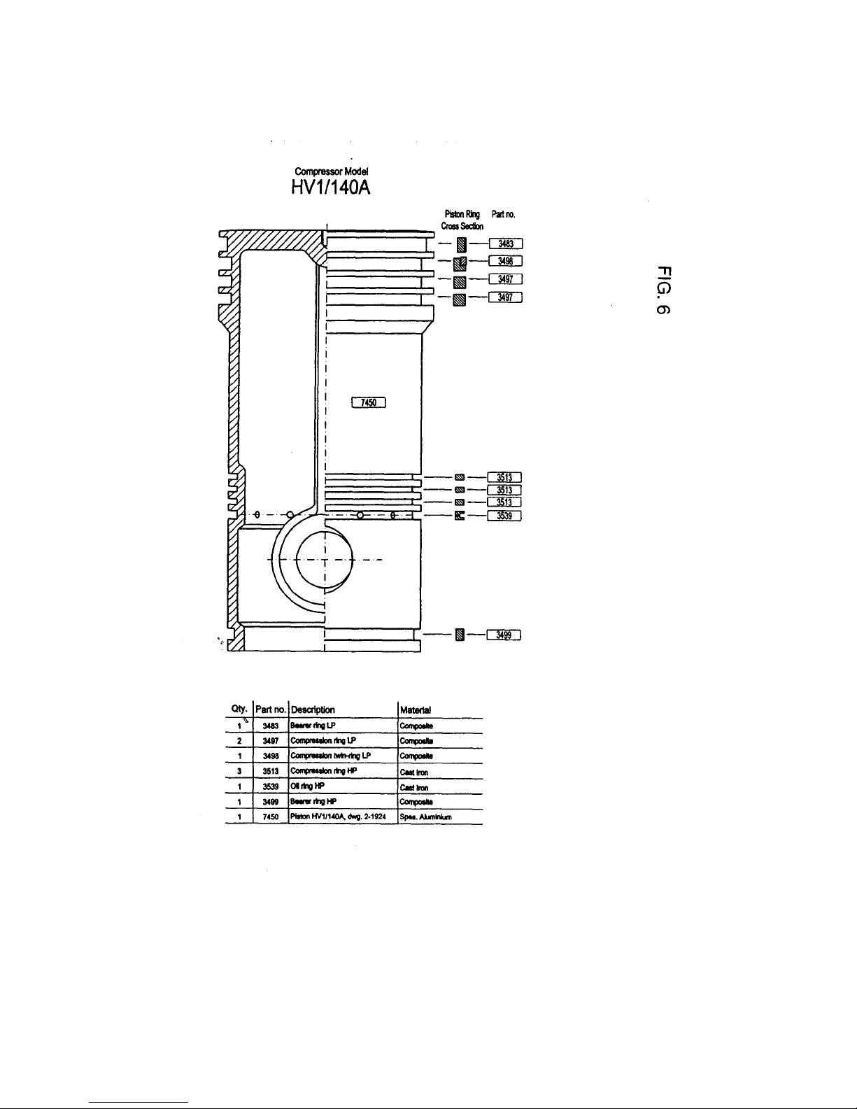
Model: HV1/140A
5.2. Valves
In the parts lists and drawings each valve is shown complete, with its own part number, and also
dismantled with the part numbers of the individual components.
After overhaul or replacement of parts, assemble the valves in sequence as shown in the
drawing of the dismantled valve.
When assembling valves, lubricate the nut and valve bolt and tighten to the torques (in kpm)
given below:
Dimension Minimum Maximum
M8 1.0 1.2
IMPORTANT:
Before attempting to check compressor valves, loosen the clamping screw on the valve cover
before removing the cover.
After inspecting and overhauling valves, it is essential that the clamping screw, which bears
against the valve clamping piece and which keeps the valve in place on its seat, should be tightened
with an unbrako key to the torque shown in Table T.3.
Overhaul and maintenance of valves
Regular and careful maintenance of valves is essential to the capacity and reliability of the
compressor. We therefore recommend overhaul in accordance with the following guidelines:
When cleaning and dismantling the valve, never clamp the valve directly in a vice to loosen the
centre bolt nut. A special clamping jig for this purpose, suitable for all valves, is available from the
factory on request. A simple makeshift for clamping the valve is to set it in a vice between two
pins which fit into the outermost seat slots of the valve.
Clean the valve components and check them carefully. IMPORTANT: Never use sharp
implements on sealing surfaces and plate parts.
Replace all parts that are worn or even slightly scored. Check that all guide pins are in order.
Maximum wear limit is 10% of the total thickness of components.
If a valve spring or spring plate shows signs of weakness, all springs must be replaced at the
same time, because damage can result if some springs operate longer than others. Replacement
of all valve springs is recommended after about 5000 hours running time, even if the springs do
not look worn.
If there are signs of abrasion or scoring of the valve seat sealing ledges, these must be
machined. Most valves are drilled for guide pins, with spare holes for new pins. Guide pins can be
driven out by means of a suitable tool. If it proves impossible to remove a broken pin, use one of
the spare holes.
To remove the valve centre bolt, mark the centre of the pin with a centre punch and then drill out
the pin. Remove the centre bolt. After refitting the bolt, drill a hole for the safety pin, drive the pin
securely into place and peen the end to prevent it from falling out.
After completion of machining and careful replacement of guide pins in their respective holes in
the valve seating and/or catch plate, check that the ends of the pins do not butt against the
bottom of the holes in the matching parts.
Use only genuine replacement pins and parts.
9/26