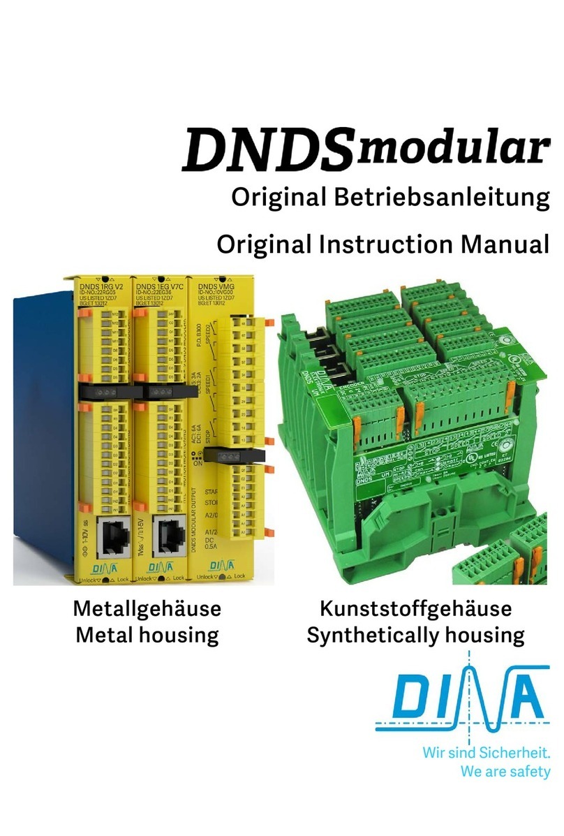
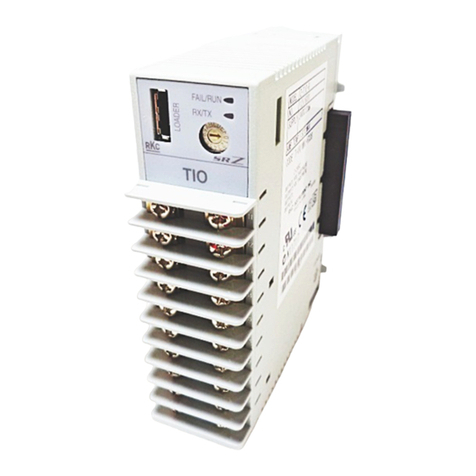
RKC INSTRUMENT SR Mini HG Use and care manual

®RKC INSTRUMENT INC.
A
ll Rights Reserved, Copyright 2006, RKC INSTRUMENT INC.
High-performance Multi-point Control System
SR Mini HG SYSTEM
Communication Quick Manual
IMS01V02-E3
Thank you for purchasing this RKC product. In order to achieve
maximum performance and ensure proper operation of your new
instrument, carefully read all the instructions in this manual.
Please place the manual in a convenient location for easy
reference.
SYMBOLS
: This mark indicates precautions that must be
taken if there is danger of electric shock, fire, etc.,
which could result in loss of life or injury.
: This mark indicates that if these precautions and
operating procedures are not taken, damage to
the instrument may result.
: This mark indicates that all precautions should
be taken for safe usage.
: This mark indicates important information on
installation, handling and operating procedures.
: This mark indicates supplemental information on
installation, handling and operating procedures.
: This mark indicates where additional information
may be located.
To prevent injury to persons, damage to instrument
and equipment, a suitable external protection device
shall be required.
All wiring must be completed before power is turned
on to prevent electric shock, fire or damage to
instrument and equipment.
This instrument must be used in accordance with the
specifications to prevent fire or damage to
instrument and equipment.
This instrument is not intended for use in locations
subject to flammable or explosive gases.
Do not touch high-voltage connections such as
power supply terminals, etc. to avoid electric shock.
RKC is not responsible if this instrument is repaired,
modified or disassembled by other than
factory-approved personnel. Malfunction can occur
and warranty is void under these conditions.
This product is intended for use with industrial machines, test
and measuring equipment. (It is not designed for use with
medical equipment and nuclear energy.)
This is a Class A instrument. In a domestic environment, this
instrument may cause radio interference, in which case the
user may be required to take additional measures.
This instrument is protected from electric shock by reinforced
insulation. Provide reinforced insulation between the wire for
the input signal and the wires for instrument power supply,
source of power and loads.
Be sure to provide an appropriate surge control circuit
respectively for the following:
If input/output or signal lines within the building are longer
than 30 meters.
If input/output or signal lines leave the building, regardless
the length.
This instrument is designed for installation in an enclosed
instrumentation panel. All high-voltage connections such as
power supply terminals must be enclosed in the instrumentation
panel to avoid electric shock by operating personnel.
All precautions described in this manual should be taken to
avoid damage to the instrument or equipment.
All wiring must be in accordance with local codes and
regulations.
All wiring must be completed before power is turned on to
prevent electric shock, instrument failure, or incorrect action.
The power must be turned off before repairing work for input
break and output failure including replacement of sensor,
contactor or SSR, and all wiring must be completed before
power is turned on again.
To prevent instrument damage as a result or failure, protect
the power line and the input/output lines from high currents
with a suitable overcurrent protection device with adequate
breaking capacity such as fuse, circuit breaker, etc.
Prevent metal fragments or lead wire scraps from falling inside
instrument case to avoid electric shock, fire or malfunction.
Tighten each terminal screw to the specified torque found in
the manual to avoid electric shock, fire or malfunction.
For proper operation of this instrument, provide adequate
ventilation for heat dispensation.
Do not connect wires to unused terminals as this will interfere
with proper operation of the instrument.
Turn off the power supply before cleaning the instrument.
Do not use a volatile solvent such as paint thinner to clean the
instrument. Deformation or discoloration will occur. Use a soft,
dry cloth to remove stains from the instrument.
To avoid damage to instrument display, do not rub with an
abrasive material or push front panel with a hard object.
Do not connect modular connectors to telephone line.
When high alarm with hold action/re-hold action is used for
Alarm function, alarm does not turn on while hold action is in
operation. Take measures to prevent overheating which may
occur if the control device fails.
NOTICE
This manual assumes that the reader has a fundamental
knowledge of the principles of electricity, process control,
computer technology and communications.
The figures, diagrams and numeric values used in this manual
are only for purpose of illustration.
RKC is not responsible for any damage or injury that is caused
as a result of using this instrument, instrument failure or
indirect damage.
RKC is not responsible for any damage and/or injury resulting
from the use of instruments made by imitating this instrument.
Periodic maintenance is required for safe and proper operation
of this instrument. Some components have a limited service
life, or characteristics that change over time.
Every effort has been made to ensure accuracy of all
information contained herein. RKC makes no warranty
expressed or implied, with respect to the accuracy of the
information. The information in this manual is subject to
change without prior notice.
No portion of this document may be reprinted, modified,
copied, transmitted, digitized, stored, processed or retrieved
through any mechanical, electronic, optical or other means
without prior written approval from RKC.
WARNING
CAUTION
!
!
WARNING
CAUTION

IMS01V02-E3
2
CONTENTS
1. OUTLINE·································································· 2
2. SPECIFICATIONS······················································ 2
3. CONNECTIONS························································· 2
4. SETTING·································································· 4
4.1 Communication Setting ············································· 4
4.2 Unit Address Setting················································· 5
4.3 Communication Requirements···································· 5
5. PROTOCOL ······························································ 5
5.1 Polling ··································································· 5
5.2 Selecting································································ 6
5.3 Communication Data Structure ··································· 7
6. COMMUNICATION IDENTIFIER LIST ···························· 8
7. TROUBLESHOOTING················································16
8. ASCII 7-BIT CODE TABLE··········································17
1. OUTLINE
This manual describes the connection method with host
computer, communication setting, protocol and communication
data of the SR Mini HG SYSTEM control unit (H-PCP-A/B
module, Function modules).
For the detail connection method when it uses RKC operation
panel and communicates with a host computer, and initial setting
data, please read if necessary the following separate manuals.
SR Mini HG SYGTEM Communication Manual
(IMSRM09-E)
SR Mini/SR Mini HG SYGTEM Supplementary Information
Initialize Settings [Extended Communications]
(IMSRM07-E)
The above manuals can be downloaded from the official RKC
website:
http://www.rkcinst.com/english/manual_load.htm
The SR Mini HG SYSTEM control unit can send/receive data
to/from host computer via RKC communication.
Communication interfaces: RS-232C, RS-422A
(Specify when ordering)
Multi-drop connection
Up to 16 units
Host computer SR Mini HG SYSTEM
control unit
(Unit address 1)
RS-422A
SR Mini HG SYSTEM
control unit
(Unit address 16)
SR Mini HG SYSTEM
control unit
(Unit address 2)
RS-422A
RS-422A
Point-to-point connection
Host computer SR Mini HG SYSTEM
control unit
(Unit address 1)
RS-232C
The RKC communication data transmission/reception
status can be checked by using the Communication tool
PROTEM2. The PROTEM2 can be downloaded from
the official RKC website:
http://www.rkcinst.com/.
2. SPECIFICATIONS
Interface: Based on RS-422A EIA standard
Based on RS-232C EIA standard
Specify when ordering
Connection method: RS-422A: 4 wire system, half-duplex
multi-drop connection
RS-232C: Pint-to-point connection
Synchronous method: Start/stop synchronous type
Communication speed: 2400 bps, 4800 bps, 9600 bps, 19200 bps
Any can be selected
Data bit configuration: Start bit: 1
Data bit: 7 or 8
Parity bit:Without, Odd or Even
Without for 8 data bits
Stop bit: 1
Protocol: Based on ANSI X3.28-1976
subcategories 2.5 and B1
Error control: Vertical parity (when parity bit is selected)
Horizontal parity
Block length: 128 bytes or less
Data types: Text: ASCII 7-bit code
Control codes:
EOT (04H), ENQ (05H), ACK (06H),
NAK (15H), STX (02H), ETB (17H),
ETX (03H)
Codes in brackets ( ) are in
hexadecimal.
Time-out time: 3 seconds
Data sending transfer time:
0 to 255 ms
Maximum connections: RS-422A: 16 units
RS-232C: 1 unit
(Maximum number of control units that
can be connected to one
communication port of host computer)
Signal logic: RS-422A
Signal voltage Logic
V (A) V (B) 2 V 0 (SPACE)
V (A) V (B) 2 V 1 (MARK)
Voltage between V (A) and V (B) is the
voltage of (A) terminal for the (B)
terminal.
RS-232C
Signal voltage Logic
3 V or more 0 (SPACE)
3 V or less 1 (MARK)

IMS01V02-E3 3
3. CONNECTIONS
Customer is requested to prepare a communication
cable fit for the control unit to be connected by the host
computer. Connection cable W-BF-01
*, W-BF-02
* and
W-BF-28
* (RKC product) can use to connect host
computer.
* If noise is a factor, customer should use a twisted pair
cable (not included) or something to that effect.
Shields of the cable are connected to SG (No. 6 pin) of
the H-PCP-A/B connector.
The 6-pin type modular connector should be used for
the connection to the H-PCP-A/B module.
Recommended model:
TM4P-66P
(Manufactured by HIROSE ELECTRIC CO., LTD.)
When the interface of H-PCP-A/B is RS-232C
Pin layout of modular connector
Power supply/CPU module
H-PCP-A/B COM.PORT1
1 Unused
2SD
3SG
4RD
5Unused
6SG
Connector pin number and signal details
Pin No. Signal name Symbol
1 Unused -
2 Send data SD (TXD)
3 Signal ground SG
4 Receive data RD (RXD)
5 Unused -
6 Signal ground SG
Wiring method
Host computerH-PCP-A/B
Shielded wire * Short RS and CS within
connector
SD (TXD)
RD (RXD)
SG
SG
SD (TXD)
RD (RXD)
SG
RS (RTS)
CS (CTS)
2
4
3
6 *
Connection example
Control unit
Connected to [COM.PORT1]
on H-PCP-A/B module
Cable type: W-BF-28-3000 (RKC product, Sold separately)
[Standard cable length: 3 m]
Connected to
communication connector
Host computer
W-BF-28
D-SUB 9 pin connector *
When the interface of H-PCP-AB is RS-422A
Pin layout of modular connector
Power supply/CPU module
H-PCP-A/B COM.PORT1
1 R (A)
2R (B)
3SG
4T (B)
5T (A)
6SG
Connector pin number and signal details
Pin No. Signal name Symbol
1 Receive data R (A)
2 Receive data R (B)
3 Signal ground SG
4 Send data T (B)
5 Send data T (A)
6 Signal ground SG
Wiring method
5
1
3
4
2
Shielded twisted pair
Pair wire Host computer
T (A)
T (B)
SG
R (A)
R (B)
SG
T (A)
T (B)
SG
R (A)
R (B)
H-PCP-A/B
6
()
()
()
()
()
()
()
()
Connection example
When the interface of host computer is RS-232C
RS-422A
RS-232C
Connected to communication connector
Control unit
Connected to [COM.PORT1]
on H-PCP-A/B module
Cable type:
W-BF-02-3000 (RKC product, Sold separately)
[Standard cable length: 3 m]
W-BF-28-3000 (RKC product, Sold separately)
[Standard cable length: 3 m]
Connected to
[COM.PORT1] Connected to [COM.PORT2]
RS-232C/RS-422A converter
COM-A (RKC product)
Host computer
D-SUB 9 pin connector *
W-BF-28
W-BF-02
Recommended RS-232C/RS-422A converter: COM-A
(RKC product)
For the COM-A, refer to the COM-A/COM-B Instruction
Manual (IMSRM33-E).
Continued on the next page.
*Use W-BF-02 communication
cable (RKC product) and
D-SUB (25P type) modular
conversion connector
(TM12RV-64-H to HIROSE
ELECTRIC CO., LTD. or
equivalent.) when connector
of host computer is D-SUB
25-pin.
*Use W-BF-02 communication cable (RKC product) and
D-SUB (25P type) modular conversion connector
(TM12RV-64-H to HIROSE ELECTRIC CO., LTD. or
equivalent.) when connector of host computer is D-SUB
25-pin.
To prevent electric shock or instrument failure, turn
off the power before connecting or disconnecting the
instrument and peripheral equipment.
!
WARNING

IMS01V02-E3
4
When the host computer is corresponding to the USB
RS-422A
Connected to USB port
of a parsonal computer
Control unit
Connected to [COM.PORT1]
on H-PCP-A/B module
Connected to
USB connector
Connected to
RS-485/RS-422A
communication
connector
USB communication
converter
COM-K (RKC product)
Host computer
W-BF-01
USB cable
(COM-K accessory)
Cable type: W-BF-01-3000 (RKC product, Sold separately)
[Standard cable length: 3 m]
Connect according to the label names as they
are without crossing the wires.
For RS-485/RS-422A communication connector
of the COM-K, do not use the solderless terminal.
Please use after processing.
T(A)
R(B)
R(A)
T(B)
Blue
Black
White
Orange
Red
SG
T (A)
R (A)
1SG 2
COM-K (RS-422A)
3
4
5
RS-485/RS-422A
communication
connector
T (B)
R (B)
Recommended USB communication converter:
COM-K (RKC product)
For the COM-K, refer to COM-K Instruction Manual
(IMR01Z01-E).
Multiple control unit connections
Connect COM.PORT2 on unit address 1 to COM.PORT1 on unit
address 2.
Control unit
(Unit address 1)
Unit address 3
Host computer
W-BF-02
Control unit
(Unit address 2)
Cable type: W-BF-02-3000 (RKC product, Sold separately)
[Standard cable length: 3 m]
Connected to [COM.PORT2]
on H-PCP-A/B module
Connected to [COM.PORT1]
on H-PCP-A/B module
4. SETTING
4.1 Communication Setting
Using the dip switches inside the H-PCP-A/B module, sets the
communication speed and data configuration.
1. To separate the module mainframe from the mother block,
press the bottom on the module, lifting upward, to release
connection.
Mother block Module mainframe
Upper
section
Mother block
Module mainframe
Lower
section
2. Data configuration and communication speed can be set with
the dip switches located in the H-PCP-A/B module.
Upper section
OFF
ON
4321
Rear view of module mainframe with mother block removed
1 2 Data configuration
OFF OFF 8-bit without parity
OFF ON 7-bit even parity
ON OFF 7-bit odd parity
ON ON Do not set this one
Factory set value: 8-bit without parity
3 4 Communication speed
OFF OFF 2400 bps
OFF ON 4800 bps
ON OFF 9600 bps
ON ON 19200 bps
Factory set value: 9600 bps
3. After communication setting is complete, place the module
mainframe opening on top of the mother block tab and snap
the lower part of module mainframe on to the mother block.
A snapping sound will be heard when module mainframe is
securely connected to mother block.
To prevent electric shock or instrument failure,
always turn off the power before setting the
switch.
To prevent electric shock or instrument failure,
never touch any section other than those
instructed in this manual.
!
WARNING
Symbol label

IMS01V02-E3 5
4.2 Unit Address Setting
When each control unit is multi-drop connected to host computer
or operation panel, set the address of each control unit using the
unit address setting switch in the H-PCP-A/B module.
Use a very small slotted screwdriver to set the unit address on
the unit address setting switch located on the front of each
H-PCP-A/B module.
8
7
6
5
4
3
2
1
0
F
E
D
C
B
A
9
H-PCP-A/B module
Setting range: 0 to 15 (0 to F: hexadecimal)
Unit address setting switch
Set the unit address such that it is different to the
other addresses on the some line. Otherwise,
problems or malfunction may result.
Number of connectable control unit: Up to 16 units
4.3 Communication Requirements
Processing times during send/receive
The SR Mini HG SYSTEM required the following processing
times during data send/receive.
Whether the host computer is using either the polling or selecting
procedure for communication, the following processing times are
required for SR Mini HG SYSTEM to send data:
-Response wait time after SR Mini HG SYSTEM sends BCC in
polling procedure
-Response wait time after SR Mini HG SYSTEM sends ACK or
NAK in selecting
RKC communication (Polling procedure)
Procedure details Time (ms)
MIN TYP MAX
Response send time after SR Mini HG
SYSTEM receives ENQ 4 7 20
Response send time after SR Mini HG
SYSTEM receives ACK 4 20
Response send time after SR Mini HG
SYSTEM receives NAK 4 20
Response wait time after SR Mini HG
SYSTEM sends BCC 1.0
RKC communication (Selecting procedure)
Procedure details Time (ms)
MIN TYP MAX
Response send time after SR Mini HG
SYSTEM receives BCC 4 7 20
Response wait time after SR Mini HG
SYSTEM sends ACK 1.0
Response wait time after SR Mini HG
SYSTEM sends NAK 1.0
Only 1 port uses communication port, and response
send time is time when interval time is set at 0 ms.
In addition, in status of the following, there is not
communication between a little.
AT end: About 0.8 seconds
Setting of initial setting item: About 0.8 to 3 seconds
Fail-safe
A transmission error may occur with the transmission line
disconnected, shorted or set to the high-impedance state. In
order to prevent the above error, it is recommended that the
fail-safe function be provided on the receiver side of the host
computer. The fail-safe function can prevent a framing error from
its occurrence by making the receiver output stable to the MARK
“1” when the transmission line is in the high-impedance state.
5. PROTOCOL
RKC communication uses the polling/selecting method to
establish a data link. The basic procedure is followed ANSI
X3.28-1976 subcategories 2.5 and B1 basic mode data
transmission control procedure (Fast selecting is the selecting
method used in SR Mini HG SYSTEM).
The polling/selecting procedures are a centralized control
method where the host computer controls the entire process.
The host computer initiates all communication so the controller
responds according to queries and commands from the host.
The code use in communication is 7-bit ASCII code including
transmission control characters.
Transmission control characters used in SR Mini HG SYSTEM:
EOT (04H), ENQ (05H), ACK (06H), NAK (15H), STX (02H),
ETB (17H), ETX (03H)
( ): Hexadecimal
5.1 Polling
Polling is the action where the host computer requests one of the
connected SR Mini HG SYSTEM to transmit data. An example of
the polling procedure is shown below:
Host
computer
send
Host
computer
send
Host computer send SR Mini HG
SYSTEM
send
SR Mini HG SYSTEM send
E
O
T
E
O
T
[BCC]
(1) (2) (5)
(3)
(4)
(9)
(7)
(10)
[Address] [ ID ] No response
[Data]
Time
out
No
response
Indefinite
E
O
T
E
O
T
S
T
X
A
C
K N
A
K
E
T
B
E
N
Q
(8)
(6)
[ ID ] or E
T
X
ID: Identifier
Polling procedures
(1) Data link initialization
Host computer sends EOT to the controllers to initiate data link
before polling sequence.
(2) Data sent from host computer - Polling sequence
Host computer sends polling sequence with the format shown
below:
3.2.1.
Identifier
A
ddress
ENQ 1ENQ
M0 2
<Example>
1. Address (2 digits)
This data is a unit address of the SR Mini HG SYSTEM for
polled and must be the same as the unit address set value in
item 4.2 Unit Address Setting (P. 5).
When it connects a host computer to an operation panel
and does host communication, address becomes 4
digits.
Operation panel
address Unit
address

IMS01V02-E3
6
2. Identifier (2 digits)
The identifier specifies the type of data that is requested from
the SR Mini HG SYSTEM. Always attach the ENQ code to
the end of the identifier.
3. ENQ
The ENQ is the transmission control character that indicates
the end of the polling sequence. The host computer then
must wait for a response from the SR Mini HG SYSTEM.
(3) Data sent from the SR Mini HG SYSTEM
If the polling sequence is received correctly, the SR Mini HG
SYSTEM sends data in the following format:
Identifier Data BCCETBSTX
3.2. 6.4.1.
Identifier Data BCCETXSTX
3.2. 6.5.1.
or
If the length of send data (from STX to BCC) exceeds
128 bytes, it is divided into blocks by ETB. In this case,
the succeeding divided data is sent after STX.
1. STX
STX is the transmission control character which indicates the
start of the text transmission (identifier and data).
2. Identifier (2 digits)
The identifier indicates the type of data (measured value,
status and set value) sent to the host computer.
3. Data
Data which is indicated by an identifier of this instrument,
consisting of channel numbers, data, etc. Each channel
number and data are delimited by a space (20H). The data
and the next channel number are delimited by a comma.
Channel number:
2-digit ASCII code, not zero-suppressed. Channels
without channel numbers may exist depending on the
type of identifier.
Data:
ASCII code, zero-suppressed with spaces (20H). The
number of digits varies depending on the type of identifier.
4. ETB
Transmission control character indicating the end of the
block.
5. ETX
Transmission control character indicating the end of the text.
6. BCC
BCC (Block Check Character) detects error using horizontal
parity and is calculated by horizontal parity (even number).
< Calculation method of BCC>
Exclusive OR all data and characters from STX through ETB
or ETX, not including STX.
<Example>
STX M 1 0 1 1 5 0 . 0 ETX BCC
4DH 31H 30H 31H 20H 20H 31H 35H 30H 2EH 30H 03H
Hexadecimal numbers
BCC = 4DH 31H 30H 31H 20H 20H 31H
35H 30H 2EH 30H 03H = 54H
( : Exclusive OR)
Value of BCC becomes 54H
(4)EOT send (Ending data transmission from the
SR Mini HG SYSTEM)
In the following cases, the SR Mini HG SYSTEM sends EOT to
terminate the data link:
When the specified identifier is invalid
When there is an error in the data format
When all the data has been sent
(5) No response from the SR Mini HG SYSTEM
The SR Mini HG SYSTEM will not respond if the polling address
is not received correctly. It may be necessary for the host
computer to take corrective action such as a time-out.
(6) ACK (Acknowledgment)
An acknowledgment ACK is sent by the host computer when
data received is correct. When the SR Mini HG SYSTEM
receives ACK from the host computer, the SR Mini HG SYSTEM
will send any remaining data of the next identifier without
additional action from the host computer.
For the identifier, refer to 6. COMMUNICATION
IDENTIFIER LIST (P. 8).
When host computer determines to terminate the data link, EOT
is sent from the host computer.
(7) NAK (Negative acknowledge)
If the host computer does not receive correct data from the SR
Mini HG SYSTEM, it sends a negative acknowledgment NAK to
the SR Mini HG SYSTEM. The SR Mini HG SYSTEM will
re-send the same data when NAK is received. This cycle will go
on continuously until either recovery is achieved or the data link
is corrected at the host computer.
(8) No response from host computer
When the host computer does not respond within approximately
three seconds after the SR Mini HG SYSTEM sends data, the
SR Mini HG SYSTEM sends EOT to terminate the data link
(time-out time: about 3 seconds).
(9) Indefinite response from host computer
The SR Mini HG SYSTEM sends EOT to terminate the data link
when the host computer response is indefinite.
(10) EOT (Data link termination)
The host computer sends EOT message when it is necessary to
suspend communication with the SR Mini HG SYSTEM or to
terminate the data link due lack of response from the SR Mini
HG SYSTEM.
5.2 Selecting
Selecting is the action where the host computer requests one of
the connected SR Mini HG SYSTEM to receive data. An
example of the selecting procedure is shown below:
Host
computer
send
[ ID ]
SR Mini HG SYSTEM
send
Host send
[Data] [BCC]
(1) (2)
(5)
(3)
(4)
(6)
[
Address
]
No res
p
onse
(7)
or
E
O
T
E
O
T
S
T
X
E
T
B
E
T
X
A
C
K
N
A
K
Selecting procedures
(1) Data link initialization
Host computer sends EOT to the SR Mini HG SYSTEM to
initiate data link before selecting sequence.

IMS01V02-E3 7
(2)Sending selecting address from the host
computer
Host computer sends selecting address for the selecting
sequence.
Address (2 digits)
This data is a unit address of the SR Mini HG SYSTEM to be
selected and must be the same as the unit address set value in
item 4.2 Unit Address Setting (P. 5).
When it connects a host computer to an operation panel
and does host communication, address becomes 4
digits.
Operation panel
address Unit
address
(3) Data sent from the host computer
The host computer sends data for the selecting sequence with
the following format:
Identifie
r
Data BCCETBSTX
3.2. 6.4.1.
Identifie
r
Data BCCETXSTX
3.2. 6.5.1.
or
If the length of send data (from STX to BCC) exceeds
128 bytes, it is divided into blocks by ETB. In this case,
the succeeding divided data is sent after STX.
Details for 1 to 6 , refer to 5.1 Polling (P. 5).
(4) ACK (Acknowledgment)
An acknowledgment ACK is sent by the SR Mini HG SYSTEM
when data received is correct. When the host computer receives
ACK from the SR Mini HG SYSTEM, the host computer will send
any remaining data. If there is no more data to be sent to SR
Mini HG SYSTEM, the host computer sends EOT to terminate
the data link.
(5) NAK (Negative acknowledge)
If the SR Mini HG SYSTEM does not receive correct data from
the host computer, it sends a negative acknowledgment NAK to
the host computer. Corrections, such as re-send, must be made
at the host computer. The SR Mini HG SYSTEM will send NAK
in the following cases:
When an error occurs on communication the line (parity,
framing error, etc.)
When a BCC check error occurs
When the specified identifier is invalid
When receive data exceeds the setting range
(6) No response from SR Mini HG SYSTEM
The SR Mini HG SYSTEM does not respond when it can not
receive the selecting address, STX, ETB, ETX or BCC.
(7) EOT (Data link termination)
The host computer sends EOT when there is no more data to be
sent from the host computer or there is no response from the SR
Mini HG SYSTEM.
The operation panel (OPC*) can correspond not only to
SR Mini HG SYSTEM communication but also to
programmable controller (PLC) communication (optional).
The PLC communication control procedure differs from
the SR Mini HG SYSTEM communication control
procedure and also from the procedure for communication
between each programmable controller manufactured by
the respective company. Therefore, in order to
discriminate PLC communication from SR Mini HG
SYSTEM communication, the former uses the identifier
(CP) dedicated to it. The PLC communication protocol
especially for the respective company is used after the
identifier (CP).
* Discontinued in November, 2006
PLC communication protocol
especially for the respective
Operation panel
address PLC
Identifier
EOT CP
5.3 Communication Data Structure
Data description (Transmission/Receive data
structure)
S
T
X
E
T
X
B
C
C
Part of the data above is shown below.
Data for each channel
Data length 6 digits
0
1
1
0
0
.
0
,
0
2
...
...
2
0
...
Data length 1 digit
0
1
,
0
2
...
2
0
Identifier
Comma
Space
Data
Data
Channel
number Channel
number
Space
Comma
Space
Data
Data
Identifier Channel
number Channel
number Channel
number Data
Space Space
DataChannel
number
Space
By data structure, channel number becomes as follows:
Data for each module:Module number
Data for each event input logic circuit:
Event input logic circuit number
Data for each unit address (Without channel)
Data length 1 digit Data length 6 digits
Identifier Data Identifier Data
.......................................................
Data

IMS01V02-E3
8
6. COMMUNICATION IDENTIFIER LIST
If you add or delete a function module, or change the arrangement of the modules, or replace a module with a different
model, be sure to perform “Module initialization (identifier CL)” before setting the data.
“Module initialization” stores the new module configuration in the H-PCP module.
If data is set before “Module initialization” is performed, the H-PCP module will set the previously stored initial data of the
old modules in the new modules, which may cause malfunction.
For details on how to initialize the module, refer to SR Mini/SR Mini HG SYSTEM Supplementary Information
Initialize Settings [Extended Communications] (IMSRM07-E).
The above manuals can be downloaded from the official RKC website:
http://www.rkcinst.com/english/manual_load.htm
Note that there are identifiers which indicate that communication is not possible depending on the specification.
Name
: Item stored in the memory area.
[ ] The functional module name that data becomes valid is written.
Attributes
RO: Read only SR Mini HG SYSTEM →Host computer
R/W: Read and Write SR Mini HG SYSTEM Host computer
WO: Write only SR Mini HG SYSTEM ←Host computer
Structure
C: Data for each channel L: Data for each event input logic circuit
M: Data for each module U: Data for each unit address
Name Iden-
tifier Digits Attri-
bute Struc-
ture Data range Factory
set value
Temperature measured value
(PV)
[H-TIO-, H-CIO-A]
M1 6 RO C
TC/RTD input:
Within input range
The position of the decimal point differs
depending on the input range.
Voltage/Current input:
Within display scale range
The position of the decimal point differs
depending on Decimal point position setting.
Alarm 1 status
[H-TIO-, H-CIO-A] AA 1 RO C 0: OFF 1: ON
Alarm 2 status
[H-TIO-, H-CIO-A] AB 1 RO C 0: OFF 1: ON
Burnout status
[H-TIO-, H-CIO-A] B1 1 RO C 0: OFF 1: ON
Heat-side manipulated output
value
[H-TIO-, H-CIO-A]
O1 6 RO C 5.0 to 105.0 %
Cool-side manipulated output
value
[H-TIO-, H-CIO-A]
O2 6 RO C 5.0 to 105.0 %
Heater break alarm status
[H-TIO-A/C/D, H-CIO-A] AC 1 RO C 0: OFF 1: ON
Current transformer input
measured value 1
[H-TIO-A/C/D]
M3 6 RO C 0.0 to 100.0 A or 0.0 to 30.0 A
Current transformer (CT) input measured value
of the H-TIO-A/C/D module
Current transformer input
measured value 2
[H-CT-A]
M4 6 RO C 0.0 to 100.0 A or 0.0 to 30.0 A
Current transformer (CT) input measured value
of the H-TIO-A/C/D module
Set value monitor
[H-TIO-, H-CIO-A] MS 6 RO C
TC/RTD input:
Within input range
The position of the decimal point differs
depending on the input range.
Voltage/Current input:
Within display scale range
The position of the decimal point differs
depending on Decimal point position setting.
Temperature rise completion
status
[H-TIO-, H-CIO-A]
HE 1 RO U 0: Rise not complete
1: Rise complete
Continued on the next page.
CAUTION

IMS01V02-E3 9
Continued from the previous page.
Name Iden-
tifier Digits Attri-
bute Struc-
ture Data range Factory
set value
Error code a
[H-PCP-A/B] ER 1 RO U 0: Operations normal
1: Backup data check error
2: RAM read/write error
3: System structure error
4: Internal communications error
5: A/D converter error
6: Adjustment data error
PID/AT transfer b
[H-TIO-, H-CIO-A] G1 1 R/W C 0: PID control operation
1: AT (Autotuning) operation 0
Temperature set value
[H-TIO-, H-CIO-A] S1 6 R/W C TC/RTD input:
Within input range (Within setting limiter)
The position of the decimal point differs
depending on the input range.
Voltage/Current input:
Within display scale range (Within setting
limiter)
The position of the decimal point differs
depending on Decimal point position setting.
0
Item stored in the memory area.
aProbable causes of occurrence
When errors 1, 2 or 5 have occurred, a breakdown in the RAM, ROM or A/D converter should be suspected.
Error 3 occurs when the module structure is different from the initial structure. An example would be if a module is replaced by a
different model of module. In this situation, replace with the same model of module. Further, this error will also occur when module
initialize has not been carried out after changing the module structure.
Error 4 occurs in the situation where a module is removed while the power is still on, etc.
If errors 5 or 6 occur, there is a possibility that too much noise, surge or strong shock has been applied to the control unit.
bAutotuning (AT) is the function which automatically measures, calculates and sets the optimum PID constants according to the set
temperature.
Caution for using the Autotuning (AT)
When a temperature change (UP and/or Down) is 1 C or less per minute during Autotuning, Autotuning may be
cancelled before calculating PID values. In that case, adjust the PID values manually. Manual setting of PID values
may also be necessary if the set value is around the ambient temperature or is close to the maximum temperature
achieved by the load.
The following is the conditions necessary to carry out autotuning and the conditions which will cause the autotuning to stop.
[Conditions necessary for autotuning]
The autotuning should be executed after satisfying all of the following conditions:
Operation mode conditions:
Auto/Manual transfer (Identifier J1) →Auto mode
PID/AT transfer (Identifier G1) →PID control mode
Control RUN/STOP transfer (Identifier SR) →Control RUN mode
The measured value (PV) is without input error range [Input error determination point (high) Measured value (PV) Input
error determination point (low)].
The output limiter high limit should be more than 0.1 % and the output limiter low limit should be less than 99.9 %.
When operation mode (Identifier EI) is set to “Normal (Can be controlled).”
When the autotuning is finished, the display of each channel automatically returns to “0: PID control operation.”
[Conditions which will cause the autotuning to stop]
When the temperature set value (SV) is changed.
When the memory area is changed.
When the PV bias value is changed.
When the AT bias value is changed.
When transfer to Manual mode using the Auto/Manual transfer.
When the measured value (PV) goes to input error range [Measured value (PV) Input error determination point (high) or
Input error determination point (low) Measured value (PV)].
When the power is cut off.
When FAIL occurs in the module whose channel is under the autotuning. Otherwise, when FAIL occurs in the H-PCP-A/B
module.
When transfer to the PID control mode by the PID/AT transfer.
When operation mode is set to “Unused,” “Monitor” or “Alarm.”
When the Control RUN/STOP function is changed to the “Control STOP” function.
When the above-mentioned conditions to stop the autotuning occurs, the autotuning is immediately stopped and
switch over to the PID control mode. The PID constants return to the values at the start of the autotuning.
Continued on the next page.

IMS01V02-E3
10
Continued from the previous page.
Name Iden-
tifier Digits Attri-
bute Struc-
ture Data range Factory
set value
Heat-side proportional band
[H-TIO-, H-CIO-A] P1 6 R/W C 0.1 to 1000.0 % of span 3.0
Cool-side proportional band
[H-TIO-, H-CIO-A] P2 6 R/W C 0.1 to 1000.0 % of span 3.0
Integral time
[H-TIO-, H-CIO-A] I1 6 R/W C 1 to 3600 seconds 240
Derivative time
[H-TIO-, H-CIO-A] D1 6 R/W C 0 to 3600 second (0: PI action) 60
Overlap/Deadband
[H-TIO-, H-CIO-A] V1 6 R/W C 10.0 to 10.0 % of span 0.0
Control response parameters
[H-TIO-, H-CIO-A] CA 1 R/W C 0: Slow 1: Medium 2: Fast
In order to perform PID control by using the
fuzzy function, specify “Fast.” The fuzzy
function is effective to restrict overshoot or
undershoot occurring at operation start, or
resulting from set value changes.
(Fuzzy function correspond to H-TIO-P/R
module only.)
0 a
Alarm 1 set value
[H-TIO-, H-CIO-A] A1 6 R/W C TC/RTD input:
Within input range or span range
The position of the decimal point differs
depending on the input range.
Voltage/Current input:
Within display scale range or span range
The position of the decimal point differs
depending on Decimal point position setting.
Refer to
Factory set
value table
of Alarm 1/
Alarm 2
set value b
Alarm 2 set value
[H-TIO-, H-CIO-A] A2 6 R/W C
Heater break alarm set value 1
[H-TIO-A/C/D] A3 6 R/W C 0.0 to 100.0 A or 0.0 to 30.0 A
Heater break alarm set value for the current
transformer (CT) input of the H-TIO-A/C/D
module
0.0
Heater break alarm set value 2
[H-CT-A] A4 6 R/W C 0.0 to 100.0 A or 0.0 to 30.0 A
Heater break alarm set value for the current
transformer (CT) input of the H-CT-A module
0.0
Operation mode transfer
[H-TIO-, H-CIO-A] EI 1 R/W C 0: Unused
If set to “Unused,” no control, monitor or
alarm monitor is performed.
1: Monitor
If set to “Monitor,” only the monitor is
performed. No control or alarm monitor is
performed.
2: Alarm
If set to “Alarm,” monitor or alarm monitor is
performed. No control is performed.
3: Normal
Selected to normal mode to perform control,
monitor or alarm monitor.
3
Item stored in the memory area.
aHeat control (H-TIO-/H-CIO-A): 0 Heat/Cool control (H-TIO-/H-CIO-A): 2 Position proportioning control (H-TIO-K): 0
bFactory set value table of Alarm 1/Alarm 2 set value
Input type Alarm type Alarm 1 set value Alarm 2 set value
TC/RTD input Process high alarm Input range (high limit) Input range (high limit)
Process low alarm
Input range (low limit) Input range (low limit)
Deviation high alarm, Deviation high/low
alarm, Band alarm 50 C * 50 C *
Deviation low alarm 50 C * 50 C *
No alarm function Input range (high limit) Input range (low limit)
Voltage/Current input Process high alarm 100.0 % 100.0 %
Process low alarm 0.0 % 0.0 %
Deviation high alarm, Deviation high/low
alarm, Band alarm 50.0 % 50.0 %
Deviation low alarm 50.0 % 50.0 %
No alarm function 100.0 % 0.0 %
* The position of the decimal point differs depending on the input range.
Continued on the next page.

IMS01V02-E3 11
Continued from the previous page.
Name Iden-
tifier Digits Attri-
bute Struc-
ture Data range Factory
set value
Heat-side proportioning cycle time
[H-TIO-, H-CIO-A] T0 6 R/W C 1 to 100 seconds
Setting will be invalid in voltage/current output. 20 a
Cool-side proportioning cycle time
[H-TIO-, H-CIO-A] T1 6 R/W C 1 to 100 seconds
Setting will be invalid in voltage/current output
and heat control.
20 a
PV bias
[H-TIO-, H-CIO-A] PB 6 R/W C 5.00 to 5.00 % of span 0.00
Control RUN/STOP transfer
[H-PCP-A/B] SR 1 R/W U 0: Control STOP 1: Control RUN
Only when the initial set mode is “0: Normal
communication,” control can be start.
0
Initial setting mode
[H-PCP-A/B] IN 1 R/W U 0: Normal communication
Normal communication is possible.
1: Extended communication (Initialize setting
mode) b
Normal and initial setting communication are
possible.
0
Memory area number
[H-TIO-, H-CIO-A] ZA 1 R/W U 1 to 8 1
Alarm interlock release
[H-TIO-, H-CIO-A, H-TI-,
H-AI-]
AR 1 WO U 1: Release (1 only)
Auto/Manual transfer
[H-TIO-, H-CIO-A] J1 1 R/W C 0: Auto
1: Manual
Setting will be invalid in ON/OFF control and
Heat/Cool control.
0
Manual output value
[H-TIO-, H-CIO-A] ON 6 R/W C 5.0 to 105.0 %
Setting will be invalid in ON/OFF control and
Heat/Cool control.
H-TIO-C/D [Z-1017 specification]:
105.0 to 0.0 % (cool-side)
0.0 to 105.0 % (heat-side)
0.0
Temperature rise completion
range
[H-TIO-, H-CIO-A]
HD 6 R/W C 1 to 10 C or 1 to 20 F 10 or 20 c
Temperature rise completion
trigger d
[H-TIO-, H-CIO-A]
HS 1 R/W C 0: Unused 1: Used
Do not set “1: Used” in H-TIO-H/J module and,
because temperature rise completion is not
judged.
0
Temperature rise completion
soak time
[H-TIO-, H-CIO-A]
T3 6 R/W U 0 to 360 minutes 0
AI measured value
[H-AI-A/B] M5 6 RO C Within display scale range
The position of the decimal point differs
depending on AI decimal point position setting.
AI alarm 1 status
[H-AI-A/B] AD 1 RO C 0: OFF 1: ON
AI alarm 2 status
[H-AI-A/B] AE 1 RO C 0: OFF 1: ON
aRelay contact output: 20 seconds
Voltage pulse output, Open collector output, Triac output: 2 seconds
b If Extended communication (Initialize setting mode) is selected, the content of each identifier described in the separate SR Mini/SR
Mini HG SYSTEM Supplementary Information Initialize Settings [Extended Communications] (IMSRM07-E)can be
changed or selected.
When the control is started, it is impossible to change the settings to the Extended communications (Initialize
setting mode). For the change to the Extended communications (Initialize setting mode), the control must be first
stopped by the “Control RUN/STOP transfer (Identifier: SR).”
The Supplementary Information Initialize Settings [Extended Communications] (IMSRM07-E)can be download
from the official RKC website: http://www.rkcinst.com/english/manual_load.htm
c TC/RTD input: 10 C or 20 F
Voltage/Current input: 10 % of display scale
dIf the channel of each of the H-TIO-H/J modules is set “1: Used,” it does no reach the completion of temperature rise. As a result,
the state of this completion (Identifier HE) which is judged by performing the OR operation of all the channels cannot be attained,
thereby continuing the incompletion of temperature rise.
Continued on the next page.

IMS01V02-E3
12
Continued from the previous page.
Name Iden-
tifier Digits Attri-
bute Struc-
ture Data range Factory
set value
AI alarm 1 set value
[H-AI-A/B] A5 6 R/W C Within display scale range
The position of the decimal point differs
depending on AI decimal point position setting.
100.0 a
AI alarm 2 set value
[H-AI-A/B] A6 6 R/W C Within display scale range
The position of the decimal point differs
depending on AI decimal point position setting.
0.0 b
AI zero point correction
[H-AI-A/B] JI 1 R/W C 0: Cancel 1: Execution 0
AI full scale correction
[H-AI-A/B] JJ 1 R/W C 0: Cancel 1: Execution 0
AI operation mode transfer
[H-AI-A/B] NJ 1 R/W C 0: Unused
Neither monitor nor alarm monitor is done in
this mode.
1: Normal
Normal mode in which monitor and alarm
are done.
1
Control loop break alarm (LBA)
status [H-TIO-, H-CIO-A] AP 1 RO C 0: OFF 1: ON
LBA use selection
[H-TIO-, H-CIO-A] HP 1 R/W C 0: Unused 1: Used 0
LBA time
[H-TIO-, H-CIO-A] C6 6 R/W C 1 to 7200 seconds 480
LBA deadband
[H-TIO-, H-CIO-A] V2 6 R/W C Input span
TC/RTD input:
The position of the decimal point differs
depending on the input range.
Voltage/Current input:
The position of the decimal point differs
depending on Decimal point position setting.
0
AO output value monitor
[H-AO-A/B] M6 6 RO C Display scale range
The position of the decimal point differs depending
on AO decimal point position setting.
Data will be valid in manual mode.
AO output set value
[H-AO-A/B] S6 6 R/W C Display scale range
The position of the decimal point differs depending
on AO decimal point position setting.
Data will be valid in manual mode.
0.0
AO function selection
[H-AO-A/B] XO 6 R/W C 0: Unused
1: Manual mode (outputs data given by the AO
output set value)
2: Temperature measured value (PV)
3: Set value monitor
4: Temperature deviation value (deviation
between the temperature measured value
and set value monitor)
5: Heat-side manipulated output value
6: Cool-side manipulated output value
7: AI measured value
8: TI measured value
9: Opening monitor
(2 to 9: Recorder output mode)
1
AO corresponding channel
setting
[H-AO-A/B]
OY 6 R/W C 1 to 20 (TIO and FBR input channel)
1 to 40 (AI and TI channel)
Setting will be valid in recorder output mode.
1
AO zooming high limit
[H-AO-A/B] CV 6 R/W C AO zooming low limit to 100.0 %
Setting will be valid in recorder output mode. 100.0
AO zooming low limit
[H-AO-A/B] CW 6 R/W C 0.0 % to AO zooming high limit
Setting will be valid in recorder output mode. 0.0
AO zero point correction
[H-AO-A/B] JK 6 R/W C 5.00 to 5.00 % 0.00
a Process high alarm: 100.0 Process low alarm: 0.0 No alarm function: 100.0
b Process high alarm: 100.0 Process low alarm: 0.0 No alarm function: 0.0
Continued on the next page.

IMS01V02-E3 13
Continued from the previous page.
Name Iden-
tifier Digits Attri-
bute Struc-
ture Data range Factory
set value
AO full scale correction
[H-AO-A/B] JL 6 R/W C 5.00 to 5.00 % 0.00
H-DI-A module input status
[H-DI-A] L1 6 RO M 0 to 255 a
Event DO status
[H-DO-C] Q3 6 RO M 0 to 255 b
Event DO manual output value
[H-DO-C] Q4 6 R/W M 0 to 255 b0
Event DO extension alarm set
value
[H-DO-C]
A7 6 R/W C TC/RTD input:
Within input range or span range
The position of the decimal point differs
depending on the input range.
Voltage/Current input:
Within display scale range or span range
The position of the decimal point differs
depending on Decimal point position setting.
0
Cascade monitor
[H-CIO-A] KH 6 RO C Input span
TC/RTD input:
The position of the decimal point differs
depending on the input range.
Voltage/Current input:
The position of the decimal point differs
depending on Decimal point position setting.
Data will be valid in slave channel
Cascade ON/OFF
[H-CIO-A] KF 1 R/W C 0: OFF 1: ON
Setting will be valid in master channel. 0
Cascade gain
[H-CIO-A] KG 6 R/W C 9.999 to 10.000
As the cascade gain is valid only in the slave
channel, the polling or selecting of the same
value is made also in the master channel.
1.000
Cascade bias
[H-CIO-A] KI 6 R/W C 99.99 to 100.00 %
As the cascade bias is valid only in the slave
channel, the polling or selecting of the same
value is made also in the master channel.
50.00
TI measured value
[H-TI-A/B/C] M7 6 RO C Within input range
The position of the decimal point differs
depending on the input range.
TI alarm 1 status
[H-TI-A/B/C] AF 1 RO C 0: OFF 1: ON
TI alarm 2 status
[H-TI-A/B/C] AG 1 RO C 0: OFF 1: ON
TI burnout status
[H-TI-A/B/C] B2 1 RO C 0: OFF 1: ON
aEach contact input status is assigned as a bit image in binary numbers. However, send data from the SR Mini HG SYSTEM be
changed to decimal ASCII code from the bit image in binary numbers.
Bit 7··········· Bit 0
Bit image: 00000000
Bit data 0: OFF 1: ON
bEach contact output status is assigned as a bit image in binary numbers. However, send data from the SR Mini HG SYSTEM be
changed to decimal ASCII code from the bit image in binary numbers.
Bit 7············ Bit 0
Bit image: 00000000
Bit data 0: OFF 1: ON
Continued on the next page.
Bit 0: CH1 (DI1) Bit 4: CH5 (DI5)
Bit 1: CH2 (DI2) Bit 5: CH6 (DI6)
Bit 2: CH3 (DI3) Bit 6: CH7 (DI7)
Bit 3: CH4 (DI4) Bit 7: CH8 (DI8)
Bit 0: CH1 (DO1) Bit 4:CH5 (DO5)
Bit 1: CH2 (DO2) Bit 5:CH6 (DO6)
Bit 2: CH3 (DO3) Bit 6:CH7 (DO7)
Bit 3: CH4 (DO4) Bit 7:CH8 (DO8)

IMS01V02-E3
14
Continued from the previous page.
Name Iden-
tifier Digits Attri-
bute Struc-
ture Data range Factory
set value
TI alarm 1 set value
[H-TI-A/B/C] A8 6 R/W C Within input range
The position of the decimal point differs
depending on the input range.
Note 1
TI alarm 2 set value
[H-TI-A/B/C] A9 6 R/W C Within input range
The position of the decimal point differs
depending on the input range.
Note 1
PV bias
[H-TI-A/B/C] PC 6 R/W C 5.00 to 5.00 % of span 0.00
TI operation mode transfer
[H-TI-A/B/C] EJ 1 R/W C 0: Unused
Neither monitor nor alarm monitor is done in
this mode.
1: Normal
Normal mode in which monitor and alarm
are done.
1
PCP module DI condition
[H-PCP-B] L3 6 RO M 0 to 7 a
Event DI contact input monitor
[H-DI-B] L4 6 RO M 0 to 255 b
Event DI logic input monitor
[H-DI-B] L5 6 RO L 0 to 15 c
Event DI logic output monitor
[H-DI-B] Q5 6 RO M 0 to 255 d
Heater break alarm status
[H-CT-A] AH 1 RO C 0: Normal 1: Break 2: Welding
aEach contact input status is assigned as a bit image in binary numbers. However, send data from the SR Mini HG SYSTEM be
changed to decimal ASCII code from the bit image in binary numbers.
Bit 7············ Bit 0
Bit image: 00000000
Bit data 0: OFF 1: ON
bEach contact input status is assigned as a bit image in binary numbers. However, send data from the SR Mini HG SYSTEM be
changed to decimal ASCII code from the bit image in binary numbers.
Bit 7············ Bit 0
Bit image: 00000000
Bit data 0: OFF 1: ON
cEach logic input status is assigned as a bit image in binary numbers. However, send data from the SR Mini HG SYSTEM be
changed to decimal ASCII code from the bit image in binary numbers.
Bit 7············ Bit 0
Bit image: 00000000
Bit data 0: OFF 1: ON
dEach logic output status is assigned as a bit image in binary numbers. However, send data from the SR Mini HG SYSTEM be
changed to decimal ASCII code from the bit image in binary numbers.
Bit 7············ Bit 0
Bit image: 00000000
Bit data 0: OFF 1: ON
Note 1: The factory set value varies depending on the alarm type.
Process high alarm: Input range (high)
Process low alarm: Input range (low)
No alarm function: Input range (high) for TI alarm 1 set value or Input range (low) for TI alarm 2 set value
The position of the decimal point differs depending on the input range. Continued on the next page.
Bit 0: CH1 (DI1)
Bit 1: CH2 (DI2)
Bit 2: CH3 (DI3)
Bit 3 to Bit 7 are unused.
Bit 0: Logic input 1
Bit 1: Logic input 2
Bit 2: Logic input 3
Bit 3: Logic input 4
Bit 4 to Bit 7 are unused.
Bit 0: Logic output 1 Bit 4: Logic output 5
Bit 1: Logic output 2 Bit 5: Logic output 6
Bit 2: Logic output 3 Bit 6: Logic output 7
Bit 3: Logic output 4 Bit 7: Logic output 8
Bit 0: CH1 (DI1) Bit 4: CH5 (DI5)
Bit 1: CH2 (DI2) Bit 5: CH6 (DI6)
Bit 2: CH3 (DI3) Bit 6: CH7 (DI7)
Bit 3: CH4 (DI4) Bit 7: CH8 (DI8)

IMS01V02-E3 15
Continued from the previous page.
Name Iden-
tifier Digits Attri-
bute Struc-
ture Data range Factory
set value
Comprehensive alarm status
[H-PCP-A/B] AJ 6 RO U 0 to 2047a
Positioning monitor
[H-TIO-K] M8 6 RO C 5.0 to 105.0 %
Positioning output neutral zone
[H-TIO-K] V3 6 R/W C 0.1 to 10.0 % of motor time 2.0
Motor time
[H-TIO-K] TJ 6 R/W C 5 to 1000 seconds 10
Integrated output limiter
[H-TIO-K] OS 6 R/W C 100.0 to 200.0 % of motor time 150.0
Manual positioning output
value
[H-TIO-K]
OO 6 R/W C 5.0 to 105.0 % 0.0
Local/computer transfer
[H-PCP-A/B] C1 1 RO U 0: Local mode
1: Computer mode
(Only valid when connected with the operation
panel)
a Each alarm status is assigned as a bit image in binary numbers. However, send data from the SR Mini HG SYSTEM be changed
to decimal ASCII code from the bit image in binary numbers.
Bit 15 ······················ Bit 0
Bit image: 0000000000000000
Bit data 0: OFF 1: ON
Name setting of operation panel (OPC*/OPC-H*)
The following names and settings are checked also on the host computer side.
Name Iden-
tifier Digits Attri-
bute Struc-
ture Data range Factory set value
Unit name NU 12 R/W U 12 characters Unit1 to 8
Memory area name NM 12 R/W C 12 characters Area1 to 8
Temperature control channel
name N1 8 R/W C
8 characters Temp1 to 20
AI channel name N2 8 R/W C 8 characters AI1 to 40
AI channel engineering unit NT 8 R/W C 8 characters %
Extension alarm channel
name NQ 8 R/W C
8 characters Alm 1 to 40
PC data name (Sequence
item name) NR 10 R/W C 10 characters
Set the unit address to "99."
The PC data name function is only for
the OPC*.
PC1 to 400
TI channel name N5 8 R/W C 8 characters TI1 to 40
AO channel name N4 8 R/W C 8 characters AO1 to 20
AO channel engineering unit NS 8 R/W C 8 characters %
Alarm message NA 32 R/W C 32 characters
Set the unit address to "99." Messages differ
depending on the
type of operation
panels.
* The following operation panels mentioned in this manual are already discontinued.
OPC (discontinued in November, 2006) OPC-H (discontinued in February, 2012)
Bit 0: Logical OR of alarm 1 status in all channels
Bit 1: Logical OR of alarm 2 status in all channels
Bit 2: Logical OR of burnout alarm status in all channels
Bit 3: Logical OR of heater break alarm status in all channels
Bit 4: Temperature rise completion status
Bit 5: Logical OR of AI alarm 1 status in all channels
Bit 6: Logical OR of AI alarm 2 status in all channels
Bit 7: Logical OR of control loop break alarm status in all channels
Bit 8: Logical OR of TI alarm 1 status in all channels
Bit 9: Logical OR of TI alarm 1 status in all channels
Bit 10:Logical OR of TI burnout alarm status in all channels
Bit 11 to Bit 15 are unused.

IMS01V02-E3
16
7. TROUBLESHOOTING
This section lists some basic causes and solutions to be taken when any problem would arise in this instrument. If you cannot solve a
problem, please contact RKC sales office or the agent, on confirming the type name and specifications of the product.
If the instrument is necessary to be replaced, observe the following warning.
All wiring must be completed before power is turned on to prevent electric shock, instrument failure, or incorrect action.
The power must be turned off before repairing work for input break and output failure including replacement of sensor,
contactor or SSR, and all wiring must be completed before power is turned on again.
If you add or delete a function module, or change the arrangement of the modules, or replace a module with a different
model, be sure to perform “Module initialization (identifier: CL)” before setting the data.
“Module initialization” stores the new module configuration in the H-PCP module.
If data is set before “Module initialization” is performed, the H-PCP module will set the previously stored initial data of the
old modules in the new modules, which may cause malfunction.
For details on how to initialize the module, refer to SR Mini/SR Mini HG SYSTEM Supplementary Information
Initialize Settings [Extended Communications] (IMSRM07-E).
The above manuals can be downloaded from the official RKC website: http://www.rkcinst.com/english/manual_load.htm
As all data on PID constants, alarm set values, etc. is managed by the H-PCP module, it is necessary to re-enter and
re-set all data when the H-PCP module is replaced.
However, re-entry and re-set are not required in the following cases.
When data backup software is operating in the module by the external host computer.
When it is set on the operation panel so that data on the operation panel side is transferred to the control unit side
when the power is turned on again.
RKC communication
Problem Possible cause Solution
No response Wrong connection, no connection or disconnection of the
communication cable Confirm the connection method or condition and connect
correctly
Breakage, wrong wiring, or imperfect contact of the
communication cable Confirm the wiring or connector and repair or replace the
wrong one
Mismatch of the setting data of communication speed
and data bit configuration with those of the host
computer
Confirm the settings and set them correctly
Wrong address setting
Error in the data format Reexamine the communication program
Transmission line is not set to the receive state after
data send (for RS-485)
EOT return The specified identifier is invalid Confirm the identifier is correct or that with the correct
function is specified. Otherwise correct it
Error in the data format Reexamine the communication program
NAK return Error occurs on the line (parity bit error, framing error,
etc.) Confirm the cause of error, and solve the problem
appropriately. (Confirm the transmitting data, and resend
data)
BCC error
The data exceeds the setting range Confirm the setting range and transmit correct data
The block data length of the transmission exceeds 128
bytes Divide the block using ETB before sending it
The specified identifier is invalid Confirm the identifier is correct or that with the correct
function is specified. Otherwise correct it
The transmission mode of the operation panel is set to
local mode Change to computer mode
CAUTION
To prevent electric shock or instrument failure, always turn off the system power before replacing the
instrument.
To prevent electric shock or instrument failure, always turn off the power before mounting or removing the
instrument.
To prevent electric shock or instrument failure, do not turn on the power until all wiring is completed. Make sure
that the wiring is correct before applying power to the instrument.
To prevent electric shock or instrument failure, do not touch the inside of the instrument.
All wiring must be performed by authorized personnel with electrical experience in this type of work.
!
WARNING

IMS01V02-E3 17
8. ASCII 7-BIT CODE TABLE
b7 0 0 0 0 1 1 1 1
b6 0 0 1 1 0 0 1 1
b5 0 1 0 1 0 1 0 1
b5~b7 b4 b3 b2 b1 0 1 2 3 4 5 6 7
0 0 0 0 0 NUL DLE SP 0 @ P ‘ p
0 0 0 1 1 SOH DC1 ! 1 A Q a q
0 0 1 0 2 STX DC2 ” 2 B R b r
0 0 1 1 3 ETX DC3 # 3 C S c s
0 1 0 0 4 EOT DC4 $ 4 D T d t
0 1 0 1 5 ENQ NAK % 5 E U e u
0 1 1 0 6 ACK SYM & 6 F V f v
0 1 1 1 7 BEL ETB ’ 7 G W g w
1 0 0 0 8 BS CAN ( 8 H X h x
1 0 0 1 9 HT EM ) 9 I Y i y
1 0 1 0 A LF SUB * : J Z j z
1 0 1 1 B VT ESC ; K [ k {
1 1 0 0 C FF FS , < L ¥ l |
1 1 0 1 D CR GS = M ] m }
1 1 1 0 E SO RS . > N ^ n ˜
1 1 1 1 F SI US / ? O _ o DEL

IMS01V02-E3 MAR. 2013
The first edition: MAY.2006 [IMQ00]
The third edition:MAR.2013 [IMQ00]
HEADQUARTERS: 16-6, KUGAHARA 5-CHOME, OHTA-KU TOKYO 146-8515 JAPAN
FAX: 03-3751-8585 (+81 3 3751 8585)
® RKC INSTRUMENT INC.
Website: htt
p
://www.rkcinst.com/
The name of each programmable controller (PLC) means the products of each manufacturer.
Company names and product names used in this manual are the trademarks or registered trademarks of the respective companies.
Other manuals for SR Mini HG
2
Table of contents
Other RKC INSTRUMENT Control Unit manuals
Popular Control Unit manuals by other brands

Zte
Zte ME3000 user manual

JUMO
JUMO mTRON B 70.4015.4 installation instructions

DEEP SEA ELECTRONICS
DEEP SEA ELECTRONICS DSEGenset DSE3110 Operator's manual

TechNexion
TechNexion PICO-WIZARD-IMX8M-MINI quick start guide

Advantage
Advantage Sentra SR Series reference guide

Quectel
Quectel EC20 Circuit diagrams