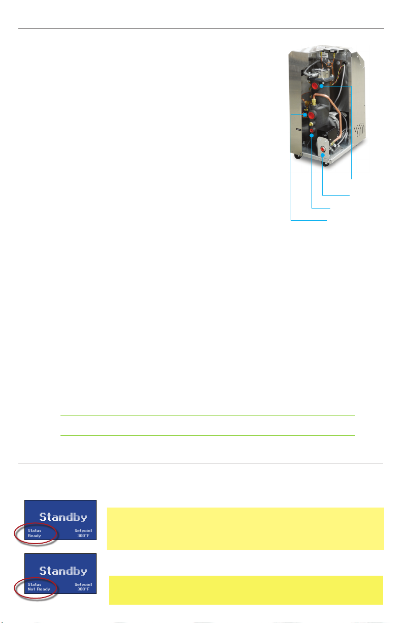
Advantage Sentra SR Series User manual

Sentra SR Series with G300 Control Instrument
This reference guide covers standard Advantage temperature control units
with the G300 Series Control Instrument.
This guide may be used for customized units using the G300 Series Control
Instrument even when the unit may not be physically the same as the units
depicted in the included photos.
Before Installing or Operating
1. A manual is available at www.advantageengineering.com/Sentra-SR-G300_Manual or by
scanning the QR code on the back of this document. Download and read the manual before
starting installation.
2. This unit is designed to be used with water as the circulating fluid. The quality of fluid used in
your temperature control unit will greatly effect its short and long-term operation. Lack of as
well as improper water treatment can damage the temperature control unit by causing scale
build-up, excessive corrosion and/or bacterial contamination. It is the equipment owner’s
responsibility to prevent damage caused by poor water quality. The services of a water
treatment professional is recommended.
3. Before installing and operating the unit, be aware of and follow any local laws and codes that
apply to the installation.
4. When contacting the Service Department always have the unit Model and Serial number from
the data tag located on the side of the unit.
SERVICE DEPARTMENT
317-887-0729
*Reference the manual for requirements for 300°F set point.
• INSTALLATION • OPERATION • TROUBLESHOOTING •
REFERENCE GUIDE
Maximum Setpoint : 300°F*

Standby
Status
Not Ready
Setpoint
300°F
Standby
Status
Ready
Setpoint
300°F
Operating Temperature
Water Supply Pressure
200°F
30 PSI
210°F
35 PSI
220°F
40 PSI
240°F
50 PSI
250°F
50 PSI
275°F
50 PSI
300°F
50 PSI
Installation
1. Electrical: Be certain all electrical connections are tight in
the unit. Install unit power cord (when supplied) to power
disconnect switch. Applied power must be equal to the unit
voltage and amps listed on the unit data tag. Follow all
applicable local and national electrical codes.
2. Plumbing: Care should be taken to use materials (hose,
rigid piping, valves or filters) rated for the temperature and
pressure duty of your unit. Most units have a maximum
operating temperature of 300°F or less and a maximum
pressure of 150 PSI. The unit is most efficient when full
size plumbing is run from the unit connections to and from
the process. If necessary, reduce the plumbing size at your
process, not at the unit.
3. Connect the unit’s To Process port to the Water In port on
the process manifold.
4. Connect the unit’s From Process port to the Water Out port
on the process manifold.
5. Note: Circuitry should avoid an excessive use of elbows
and/or lengths of pipe or hose. If hose is the material of
choice, avoid tight twists or curls and excessive lengths.
6. Valves and lters may be installed in the process water
piping circuitry to facilitate service and maintenance,
provided that such devices maintain the full inside diameter
of the process connection. If installed, all such devices must
be open and clean during unit operation.
7. Connect Unit drain to plant’s open drain, tower water
system return or chilled water system return. The factory
recommends a minimum of 20 psi pressure differential
between the water supply and drain line. A larger differential
may be required for larger cooling needs.
8. Connect Unit water supply to plant’s city water or well
water source or tower water supply or chilled water supply.
Water supply pressure requirements vary with operating
temperatures as shown in the chart below.
WARNING: proper care should be employed when checking pump rotation as
power is applied to the unit at this point.
Drain
To Process
From Process
Water Supply
Starting Unit
1. Fill unit with water. Apply power. The Standby screen will illuminate. When Standby is displayed,
the unit is not running.
• Status : Ready. Indicates the unit is ready to start.
• Status : Not Ready. Indicates the presence of a sensor probe,
pressure switch or motor overload fault. See the troubleshooting and
maintenance portions of the manual for Information. The fault must be
corrected in order to continue operation of the unit.
2. Determine the pump is rotating in a clockwise direction when viewed
from the rear of the motor. Instructions are in the operations manual.

78°F
Setpoint : 300°F
Autovent
To Process
Standby
Status
Ready
Setpoint
300°F
78°F
Setpoint : 300°F
Heating : 100%
To Process
78°F
Setpoint : 300°F
Autovent
To Process
Standby
Status
Ready
Setpoint
300°F
300°F
Setpoint : 300°F
Heating : 10%
To Process
85°F
Setpoint : 85°F
Heating : 0%
To Process
300°F
Setpoint : 85°F
Cooling : 100%
To Process
Pump Seal Cool
Wait - Shutting Down
Push Stop again to abort
85°F
Setpoint : 85°F
Heating : 0%
To Process
Pump Seal Cool
Wait - Shutting Down
Push Stop again to abort
85°F
Setpoint : 300°F
Autovent
To Process
85°F
Setpoint : 300°F
Heating : 100%
To Process
300°F
Setpoint : 85°F
Cooling : 100%
To Process
If the Pump Seal Cooling feature is NOT enabled ...
If the Pump Seal Cooling feature IS enabled ...
Setpoints
Utilites
Network
Features
Flow
Main Menu
Back Go
Pick
Controller
The instrument has 5 soft keyed buttons.
1. The Home button shows the Home screen.
2. The Up button will add one unit of value or will scroll up through a menu.
3. The Down button will subtract one unit of value or will scroll down
through a menu.
4. The Go button will advanced through a series of screens or save a
value.
5. The Back button will go backwards through a series of screens.
WARNING: When the pump seal cooling
feature is activated, pressing the stop button
will not turn off the unit. To completely shut
down the unit, press the Stop button twice.
3. The unit is ready to start when the Status
: Ready is shown on the screen and
pump rotation is correct. Press the green
start button. The unit will auto vent if the
fluid temperature is below 100°F or as
programmed in the features menu.
4. Adjust the setpoint to the desired value by
pressing the Up or Down button until the
value is displayed. The unit will heat or cool
to maintain the setpoint temperature.
Stop Unit
Starting Unit continued
1. Decrease the setpoint temperature lower
than 85°F and allow the unit to cool to the
temperature.
2. Press the Stop Button to disengage the
pump.
3. Caution. Dissipate static pressure prior to
disconnecting hoses.
4. A pump seal cooling feature can be selected
from the features menu to automatically cool
the unit once the stop button is pressed.
Operating Screens ... these show the To Process temperature, the selected Setpoint temperature
and status of Autovent, Heating and Cooling. When enabled, the Pump Seal Cool screen appears
when the unit is stopped. The pump will continue to run and the cooling valve will open 100% to
reduce process temperature prior to shutdown.
Setpoint ... use the Go button to advance to the Setpoint
select screen. Use the Up and Down buttons to select the
setpoint. Save the setting by pressing the Go button.

85°F
Setpoint : 300°F
Autovent
To Process
Setpoints
Utilites
Network
Features
Flow
Main Menu
Back Go
Pick
Autovent Time
Autovent Temp
Pump Seal Cool
Pump Seal Time
Pump Seal Temp
Features
Back Go
Pick
Mold Purge
Manual Vent
Software Version
Display Test
Utilites
Back Go
Pick
Protocol
Baud Rate
Address
Network
Back Go
Pick
Enable
Offset
Calibration
Flow
Back Go
Pick
Mold Purge
Remote Start
Options
Back Go
Pick
Valve Size
Max Setpoint
Units
Machine
Back Go
Pick
FAULT
System Safety
Check water supply
Check pump overload
FAULT
High Temp Limit
Check for cause and allow
unit to cool before
restart
FAULT
High Temp Limit
Check for cause and allow
unit to cool before
restart
FAULT
AVT Cooling Valve
Check position switch
Replace valve
FAULT
To Process Sensor
Check sensor is connected
Check connector is dry
FAULT
Phase
SRG-300
For Current Factory Operations Manual
Scan this QR code to download an PDF copy to a smart phone or tablet.
Download the PDF copy to a desktop computer for view or print by this link:
www.advantageengineering.com/Sentra-SR-G300-Manual
If you have any questions regarding this Reference Guide, the Sentra G300 Series Operations
Manual, installation, operation or servicing of the unit, please call the Advantage Service
Department.
317-887-0729
Unit Will Not Start
(Display is Blank & Off)
1. Fuse open at power
disconnect switch.
2. Transformer fuse open
Unit Will Not Start
(Display is On)
1. Error or alert indicator
displayed.
2. Follow instructions on screen
to troubleshoot and refer to
manual or contact the service
department.
Unit Overheats
1. Low water supply pressure.
2. Cooling solenoid valve
defective.
3. Drain line obstructed.
4. Instrument defective.
5. Cooling requirement exceeds
cooling valve capacity.
Unit Underheats
1. Process water leakage -
defective cooling solenoid
valve.
2. Heater element failure.
3. Process heating requirement
exceeds unit heating
capability.
4. Control instrument defective
and not calling for heat.
Pressure Relief Valve Leaks
1. Water supply pressure too
high. See manual.
2. Pressure relief valve
contamination.
525 East Stop 18 Road, Greenwood, IN 46143 phone: 317-887-0729 fax: 317-881-1277
Form #ADV-1089 updated 03/21/2023 ©2023 Advantage Engineering, Inc.
Controller
Troubleshooting
Main Menu ... from the Operating Screen,
press the Go button to advance to the Main
Menu.
Screens ... there are six screens
to set and view machine operating
parameters. Use the Go button to
advance screens from the Main
Menu. Please note, the Flow menu
requires optional components
that may not be installed on your
machine.
Basic Troubleshooting is shown here. Refer to the Operations Manual for full information.
Consult the operation manual for details regarding Fault Screen troubleshooting
This manual suits for next models
9
Other Advantage Control Unit manuals
Popular Control Unit manuals by other brands

Texas Instruments
Texas Instruments UCC27288EVM user guide

schmersal
schmersal SRB402EM operating instructions

Miele
Miele XKM 3100 W Fitting and installation instructions

Seneca
Seneca MyBoat-WR user manual

Burkert
Burkert 0470 operating instructions

Notifier
Notifier FDM-1 Installation and maintenance instructions