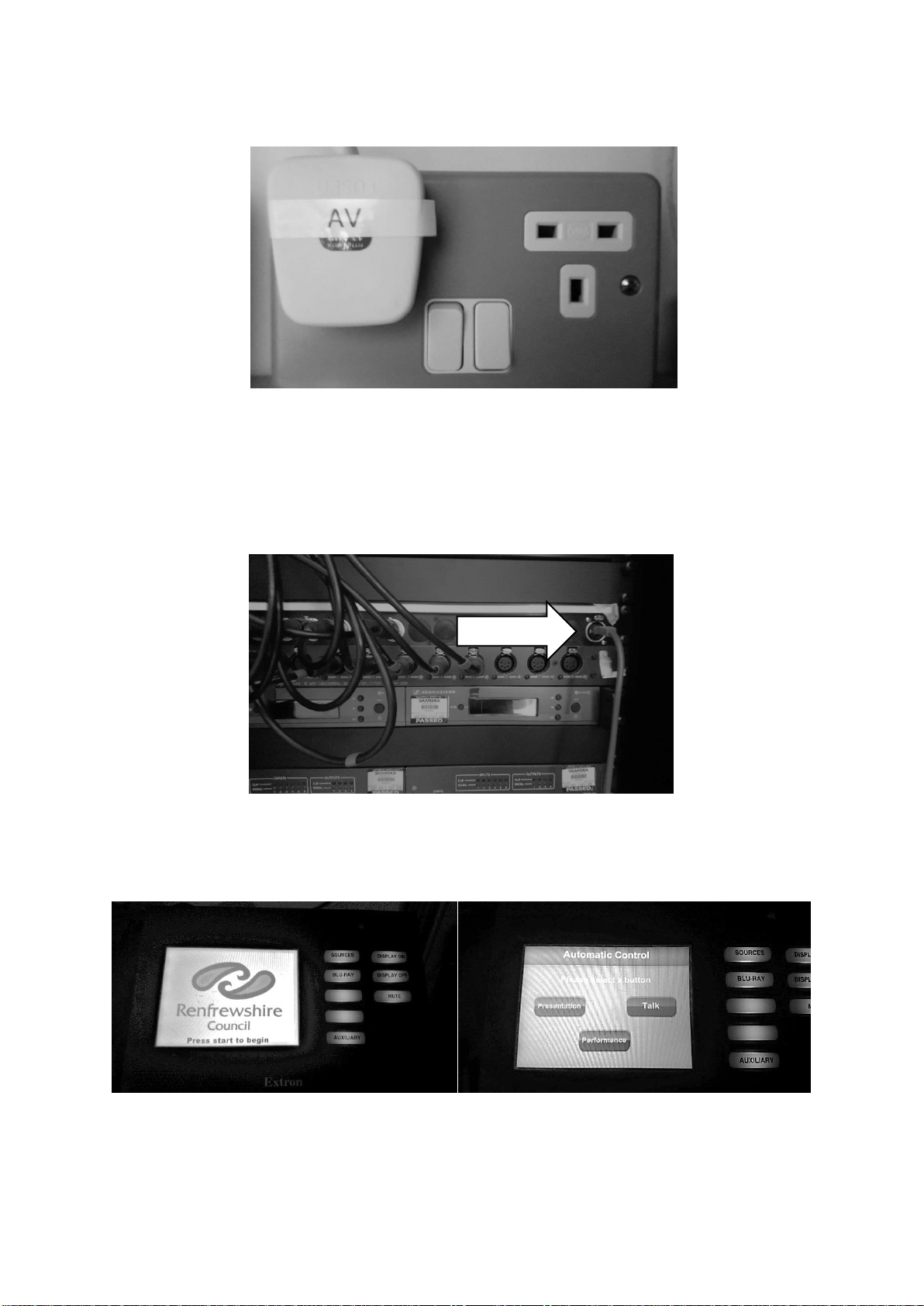
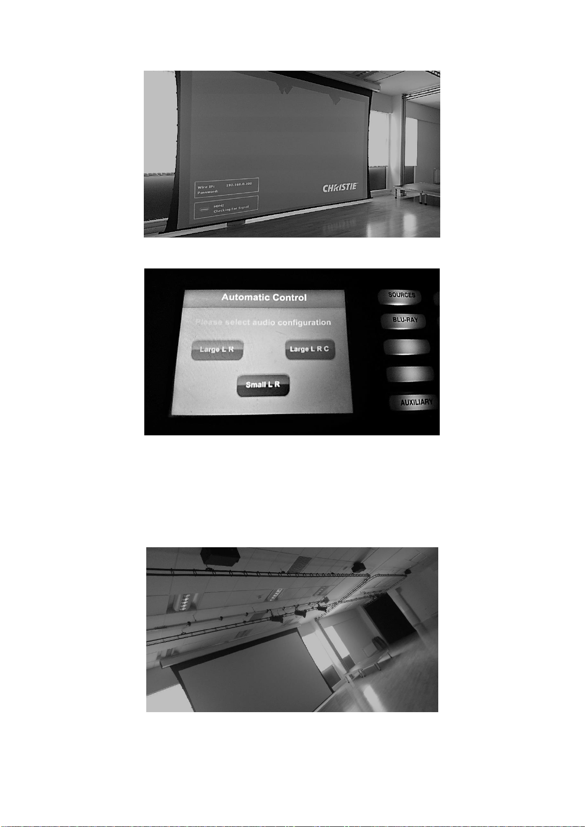
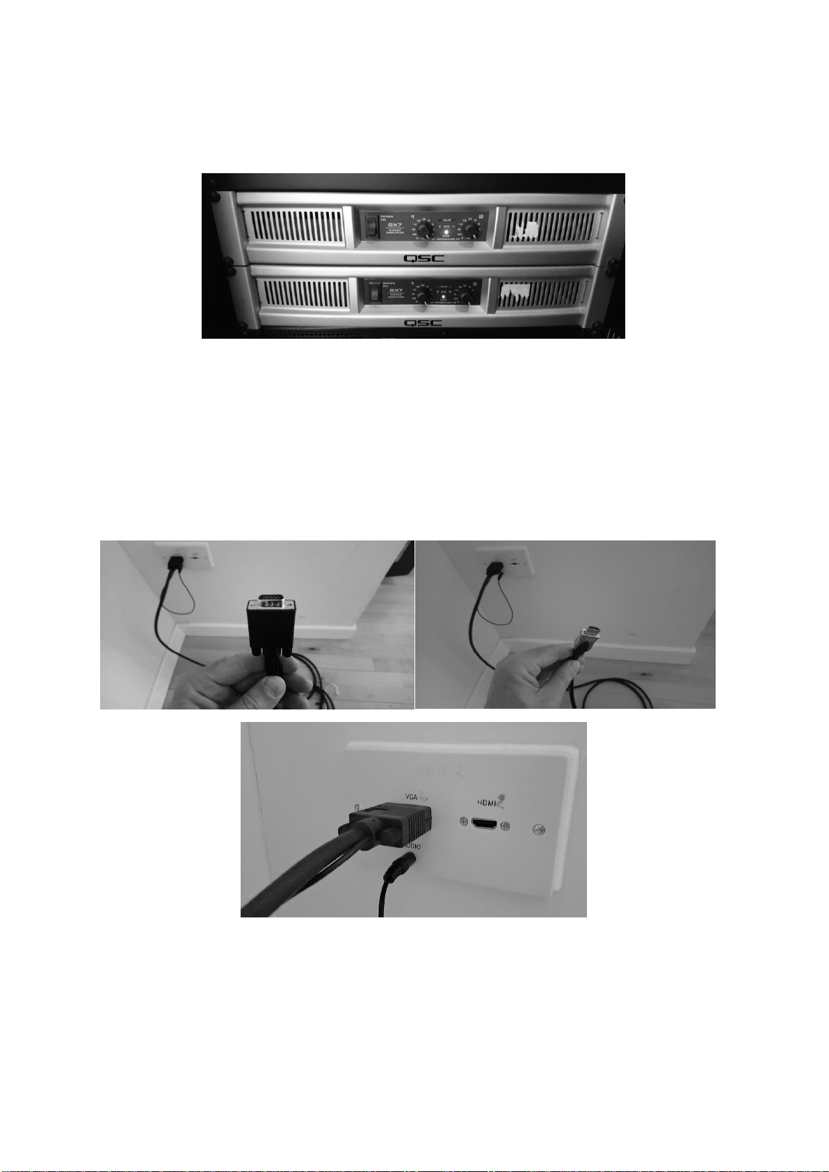
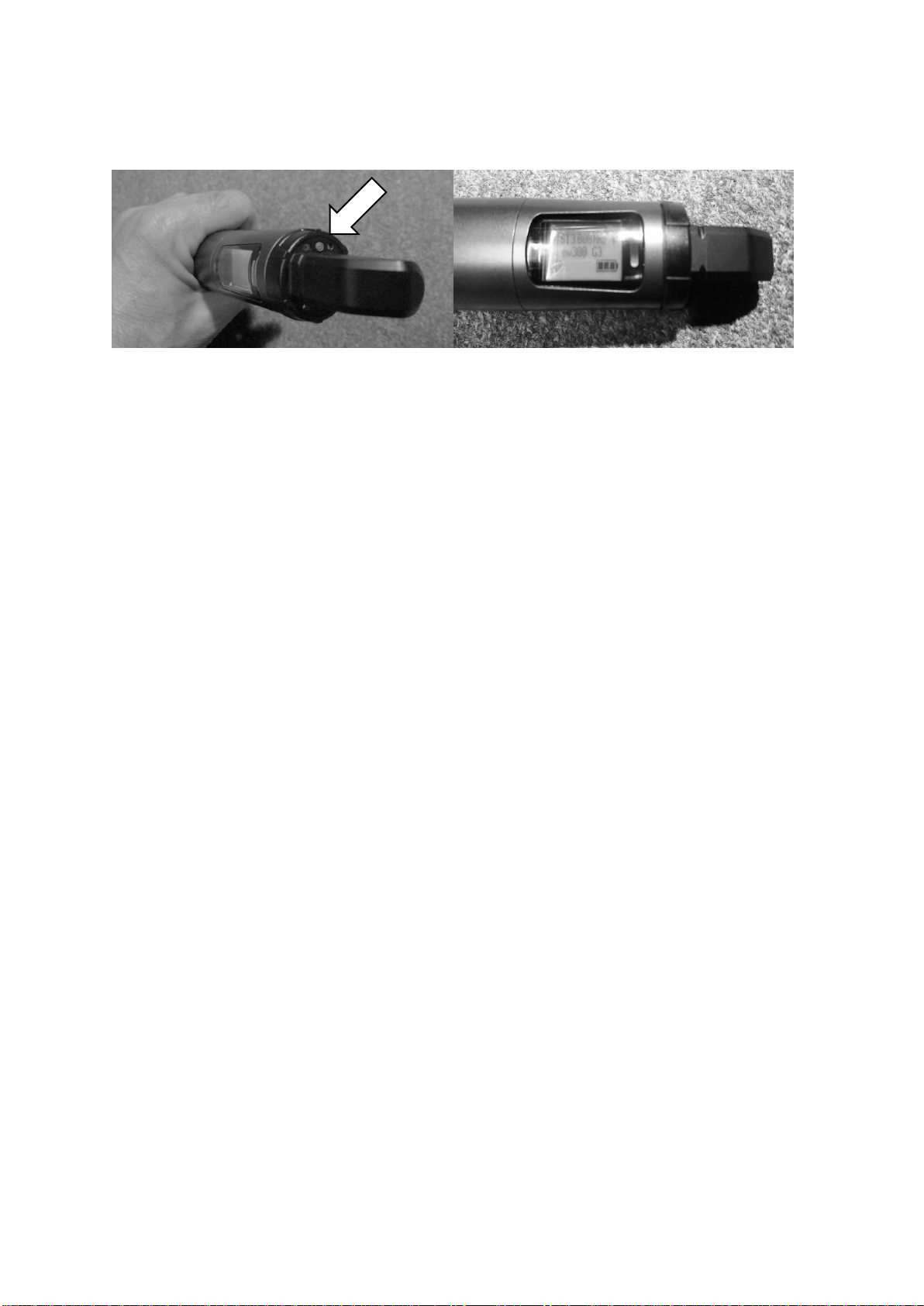
RL TWEEDIE HALL Quick start guide


Popular Projection Screen manuals by other brands

Da-Lite
Da-Lite SENIOR ELECTROL Instruction book

Rostra
Rostra 250-8274 Installation & owners guide

Screen Research
Screen Research X4R installation manual

Vivid
Vivid VFS492SVS user manual

Avers Screens
Avers Screens Electric projection screen user manual

Draper
Draper Ultimate Access Series E Installation & operating instructions

Simply Elegant
Simply Elegant 220-111 Assembly and installation instructions

Grandview
Grandview Skyshow Series user manual

Cima
Cima Below Ceiling ElectriScreen owner's manual

Recordex
Recordex Motorized Electric Projection Screen user manual

Kohler
Kohler Aerie K-12345M Installation and care guide

Barco
Barco OV-808 installation manual

Draper
Draper Rolleramic Electric Projection Screen Installation & operating instructions

Enwork
Enwork Skyline Compression Topper Screen installation guide

Da-Lite
Da-Lite Designer Contour® Specification data

REMACO TECHNOLOGIES
REMACO TECHNOLOGIES PRO-L3030 manual

Elite Screens
Elite Screens Elite Home 2 Series user guide

Elite Screens
Elite Screens AEON series user guide