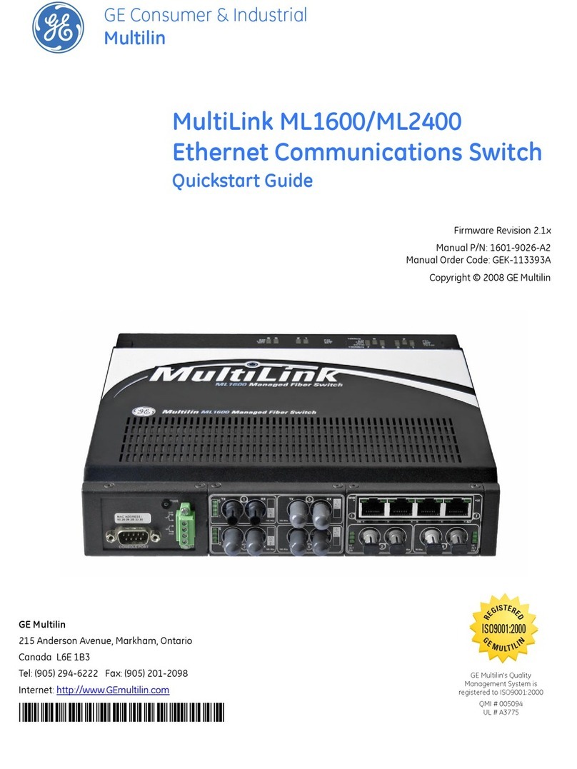
RLH Industries RLH-ESM1608-04-1 User manual

16+8 Industrial Managed!
Ethernet Fiber Switch
User Guide
U-044 2017A-0425
RLH Industries, Inc.

RLH Industries, Inc."
Copyright © 2014 RLH Industries, Inc. All rights reserved."
No part of this document may be copied or distributed without
permission.
The RLH logo may not be used for commercial purposes without the
prior written consent of RLH and may constitute trademark infringement.
Other company and product names mentioned herein are trademarks of
their respective companies. Mention of third-party products is for
informational purposes only and constitutes neither an endorsement nor
a recommendation. RLH assumes no responsibility regarding the
performance or use of these products.#
The information contained in this document is the property of RLH
Industries, Inc. and may not be reproduced or disseminated to third
parties without the express written permission of RLH.#
Every effort has been made to ensure that the information in this manual
is accurate. RLH is not responsible for printing or clerical errors. Because
we are constantly seeking ways to improve our products, specifications
and information contained in this document are subject to change
without notice.#
RLH Industries, Inc."
936 North Main Street"
Orange,CA 92867"
"
Ph. 714 532-1672"
email: info@fiberopticlink.com"
www.fiberopticlink.com#
!"
2

Contents
1.%Important Information#
Intended Audience 6
Conventions 6
General Safety Practices 6
2.%Introduction#
Product Description 7
Standard Features 7
Application Diagram 8
Front Panel 8
Front Panel Components%8#
Front Panel LEDs%9#
Rear Panel 9
Rear Panel Components%9#
Power Input%9#
Download Program Port%10#
Communication Ports%10#
10Base-T /100Base-TX Ethernet ports%10#
100Base-FX fiber port%11#
3.%Before Installing#
Observe Special Handling Requirements 12
Be careful when handling electronic components%12#
Guidelines for handling terminated fiber cable%12#
Prepare for Installation 13
Check for shipping damage%13#
Verify system contents%13#
Verify matching optical module and fiber modes%13#
Site Requirements 14
Site selection%14#
Required power sources%14#
Contents 3

4.%Quick Start Guide#
Easy Installation 15
Install the Switch%15#
Connect power%15#
Connect fiber cables%15#
Connect ethernet cables%15#
5.%Configuring the System#
Managing with Hyper Terminal 16
Modification of IP Address%17#
Web Management 18
Network Setting%18#
Startup and Log in%19#
System Status%20#
System Status%21#
Port Configuration%23#
Broadcast Storm Suppression%26#
L2 Features %27#
VLAN%27#
Port based VLAN%28#
IEEE 802.1Q VLAN%28#
IGMP Snooping%30#
Qos 32
QOS Classification%32#
Default Priority%32#
COS%33#
DSCP%33#
Redundancy%34#
Single Ring Configuration of Ring V2%37#
Coupling Ring Configuration of Ring V2%38#
Ring V3 Coupling%40#
Ring V3 Chain Configuration%41#
Access Control%42#
Access Profile%43#
Static Unicast FWD%44#
Static MAC Address%44#
Contents4

Port Statistics 46
Rx Frame Statistics%46#
Tx Frame Statistics%47#
Traffic Statistics%48#
MAC Address%48#
Diagnosis 50
Port Mirroring%50#
Diagnosis%51#
System 52
Device IP%52#
IP Address%52#
Subnet Mask%52#
Default Gateway%53#
DNS Address%53#
System File Update%53#
Logout Exit from the WEB interface.%55#
Default Settings%57#
6.%Specifications#
General Specifications 58
7.%Troubleshooting#
First Step: Isolate the problem 59
Common Issues 59
8.%Ordering Information#
Part Number and Configurations 60
9.%Support#
Technical Support 61
Contact Information 61
Contents 5

1."Important Information
Intended Audience
This manual is intended for use by knowledgeable telco/network installation, operation and repair personnel.
Every effort has been made to ensure the accuracy of the information in this manual is accurate. However,
due to constant product improvement, specifications and information contained in this document are subject
to change without notice.#
Conventions
Symbols for notes, attention, and caution are used throughout this manual to provide readers with additional
information, advice when special attention is needed, and caution to prevent injury or equipment damage.#
Notes: Helpful information to assist in installation or operation.#
Attention: information essential to installation or operation.#
Caution: Important information that may result in equipment damage or injury if ignored.#
General Safety Practices
The equipment discussed in this manual may require tools designed for the purpose being described. RLH
recommends that installation and service personnel be familiar with the correct handling and use of any
equipment used, and follow all safety precautions including the use of protective personal equipment as
required.#
Caution - Severe Shock Hazard#
•Never install during a lightning storm or where unsafe high voltages are present.#
•Active T1 lines carry high DC voltages up to 56V. Use caution when handling T1 wiring.#
Laser Safety#
•Radiation emitted by laser devices is dangerous to to human eyes.#
•Avoid eye exposure to direct or indirect radiation.#
•Do not operate without fiber cable attached or dust caps installed.#
Important Information6

2."Introduction
Product Description
The RLH Managed Ethernet Switch is a smart managed switch that offers 16 10/100Base-T(x) RJ-45 TCP
ports together with 8 100Base- FX fiber connectors. The optical interfaces may be dual fiber single mode or
multimode, or bi-directional single fiber, and have a transmission up to 120Km/74 miles.#
The switch can be managed through it’s imbedded Web Interface, with simplified settings accessible through
the console port, and also supports external alarm functions for alarm input monitor purposes. It supports
Port based VLAN and IEEE802.1Q VLAN, VLAN groups and VLAN IDs can be created. It also supports
Broadcast storm control, Port bandwidth control, QOS, etc.#
The switch may be used to establish SW-Ring for accomplishing redundancy for an Ethernet ring network
topology. The intelligent redundancy system has a short self-recovery time for automatic recovery of the
network section.#
The RLH Managed Ethernet Switch uses only 1RU and comes complete with EIA19” rack ears for rack mount
applications, or it may be used on a desktop or shelf. The fiber optic ports allow for Ethernet network
extension over long distances, and fiber optic cable provides electrical isolation between devices. It is ideal
for institutional use, medium/small enterprises and intelligent community networks that need to
accommodate various services such as video, VOIP and high speed data over fiber.#
The RLH 16+8 Ethernet Switch comes complete with an internal 115/220VAC power supply, and is covered
by a 5 year warranty.#
Standard Features
16 port 10/100M TCP ports & 8 100Base FX fiber ports.
Port mirroring for online debugging and monitoring network status.
IEEE 802.3,IEEE 802.3u,IEEE 802.3ad, IEEE 802.3z, IEEE
802.1w, IEEE 802.1D, IEEE 802.1x compliant.
Supports port trunk function and 3 groups of trunking links, port
mirroring, port priority,TOS priority.
Supports IEEE 802.3x flow control for full-duplex mode
and collision-based back-pressure for half- duplex mode.
Supports SW-Ring technology SW-Ring patented technology(self-
recovery time <20ms).
RJ-45 ports are auto MDI/MDIX, auto negotiating.
Supports 8K MAC addressing.
IEEE802.1P QoS, WRR and DSCP.
IGMP snooping for filter multicast.
Supports IP address setting and dynamic learning
(DHCP).
Built-in power supply, 115/220VAC.
No fan, low consumption design.
19” 1RU rack mount steel enclosure, Industrial grade 4 design.
-40 #F to +167 #F (-40 #C to +75 #C) operating temp.
Rugged with high strength shell with IP30 protection.
Introduction 7
•Verify or repair before continuing

Application Diagram
#
Front Panel
$
Front Panel Components
RLH MODBUS TCP TO
RTU/ASCII CONVERTER
ROUTER
LAN/WAN
T1 NETWORK
WIRELESS
T1 NETWORK
WIRELESS
MODBUS RTU/ASCII
MODBUS DEVICE
MODBUS ETHERNET
RLH 16x1 T1
OVER ETHERNET
RLH 16x1 T1
OVER ETHERNET
ETHERNET
FIBER
ETHERNET
SW RING
RLH RS-422/485
ETHERNET
CONVERTER
RLH 16+8 ETHERNET
FIBER SWITCH
RLH 16+8 ETHERNET
FIBER SWITCH
RLH 16+8 ETHERNET
FIBER SWITCH
RLH 16+8 ETHERNET
FIBER SWITCH
SERIAL
DEVICE
SERIAL
DEVICE
SERIAL
DEVICE
ETHERNET
RS-422/485
SERVER
ACESS
POINT
DEVICE
VOIP
IP
VIDEO
Link/ACT
NA
Not UsedNot Used
CONSOLE
PWR
ALARM
RUN TEST 1
2
3
4
5
6
7
8
9
10
11
12
13
14
15
16
17
18
19
20
21
22
23
24 8
+
6FIBERRJ-45 TCP
MANAGED ETHERNET SWITCH
RLH Industries, Inc.
FIBER RJ-45 TCP
1
2
3
4
5
6
7
Item
Description
1
Console Port
2
Link/ACT LED indicators
3
RUN LED
4
Test Button
5
ALARM LED
6
PWR LED
7
Link/ACT LED port identifier table
Introduction8

Front Panel LEDs
Note:%The alarm condition is set through the management software.#
Rear Panel
#
Rear Panel Components
Power Input
A 3 position terminal block on back panel is used for 100-240VAC/DC.#
#
LED
Color
State
State
PWR
GRN
ON
Power is working normally
OFF
Power is not connected or not operating normally
RUN
GRN
Blinking
System is operating normally
OFF
System is not connected or operating normally
ALARM
GRN
ON
Alarm condition is detected and alarm relay is closed
OFF
No alarm condition present and alarm relay is open
Link/ACT
GRN
ON
Network connection of the port is valid
Blinking
Activity is detected and data is being transmitted
OFF
Network connection of the port is not valid
1
2
4
5
3
18
16141210 20 22 24
171513119
8642
7531 19 21 23
ALARM RELAY INPUT: 90~240VAC
N/–L/+
MANAGED 24 PORT
ETHERNET FIBER SWITCH
RLH Industries, Inc.
fiberopticlink.com
Item
Description
1
100BaseT(X) Ethernet Ports
2
100Base-FX Fiber Optic Ports
3
Model number and MAC address
4
Alarm terminal block (Normally open)
5
Power terminal block
Introduction 9

Download Program Port
The RLH fiber switch has 1 download program port (RJ45 type) designated CONSOLE on the front panel, It
manages the system with PC through RJ45-DB9F adapter.#
#
Communication Ports
The switch has 16 10/100BaseT(X) Ethernet ports and 8 100M fiber ports. The pinout of the RJ45 ports
connect to UTP or STP. The cable length may not be more than 100m. 100Mbps Ethernet connector takes
100Ωof UTP 5, 10Mbps Ethernet connector takes 100Ωof UTP 3, 4, 5.#
#
10Base-T /100Base-TX Ethernet ports
The RJ45 ports support auto MDI/MDI-X connections. It can connect directly to PCs, Servers, Converters
and HUBs. Corresponding connection of Pin 1,2,3,6 is like this: 1→3, 2→6, 3→1, 6→2. The Pin-out definition
is displayed as below.#
#
Introduction10

MDI (straight-through cable):#
#
MDI-X (Cross over cable):#
100Base-FX fiber port
100Base-FX port works with full-duplex, SM or MM SC/ST. The fiber port may contain single fiber
bidirectional connectors, or dual fiber connectors. Dual fiber connectors must be used in pairs. The TX
(transmitting) port connects to the remote switch’s RX (receive) port; RX (receiving) port connects to the
remote switch’s TX (transmitting) port.#
We advise to label the two sides of the cable with the same letter (A-to-A and B-to-B, shown as below, or A1-
to-A2 and B1-to-B2, etc.).#
#
Introduction 11

3."Before Installing
Observe Special Handling Requirements
Be careful when handling electronic components
#
•This product contains static sensitive components. #
•Handle the modules by their faceplates only, do not touch the circuit boards or components.#
•Follow proper electrostatic discharge procedures.#
This contains components that may be damaged by static electricity. When transporting modules, carry it in an ESD safe
container such as the antistatic bag provided with the module. Before installing or replacing modules, discharge yourself of
static electricity by physical bodily contact with earth ground. When handling modules, hold by the faceplate only and avoid
touching circuitry. Failure to follow ESD precautions may cause serious damage to the modules and prevent proper
operation.#
Guidelines for handling terminated fiber cable
#
•Do not bend fiber cable sharply. Use gradual and smooth bends to avoid damaging glass fiber.#
•Keep dust caps on fiber optic connectors at all times when disconnected.#
•Do not remove dust caps from unused fiber.#
•Keep fiber ends and fiber connectors clean and free from dust, dirt and debris. Contamination will cause signal
loss.#
•Do not touch fiber ends.#
•Store excess fiber on housing spools or fiber spools at site#
ATTENTION
ELECTROSTATIC
SENSITIVE
DEVICES
Before Installing12

Prepare for Installation
Check for shipping damage
Carefully unpack and inspect the unit and accessories. Contact RLH immediately if any components are
damaged or missing. Electronic components, fiber optic cable, and accessories have special handling
requirements to prevent damage and enhance system reliability.#
If the switch will be relocated in the future, save the cartons and protective packaging material.
Verify system contents
The following items are shipped with your RLH Fiber Switch (as applicable)#
•User manual#
•AC power converter and cord#
•Serial cable adapter for use with the console port#
•Rack mount ears and attaching hardware#
•Rubber feet for table or self mount applications#
Verify matching optical module and fiber modes
Fiber mode and optical module mode must be the same. Test the fiber cables before installation.#
#
Multimode
Same Fiber Mode:
Fiber Optic
Cables
T-1 Fiber Optic
Link Card
Mode
Label
Single Mode
OR
Fiber Type
Color
Identifier
Single Mode
Yellow
9/125µm
Multimode
Orange
50 /125µm, 62.5/125µm
Before Installing 13

Site Requirements
Site selection
Locate the switch to allow easy access to the equipment. Leave at enough clearance in the front and rear to
gain access to the fiber, ethernet alarm and power connections.Typical application environments#
Route the fiber optic cable to the installation area before installing the switch.#
Required power sources
You will need an acceptable power source. The RLH FIber Switch accepts 90 ~ 280VAC (50/60Hz).#
The F.C.C. requires telecommunication equipment to withstand electrical surge that may result from lighting
strikes. This equipment has been tested and found to comply with the F.C.C. requirement. Users should
follow the precautions below to insure the safety and minimize the risk of damage to the equipment#
Make sure that the AC power outlet is properly grounded. Proper grounding should include a minimum of a
grounded rod buried outside the building at least 8 feet (2.44 meters) deep.#
Before Installing14

4."Quick Start Guide
Easy Installation
Before starting
•Review the safety information in section 1. Important Information#
•Familiarize yourself with the fiber switch as described in section 2. Introduction#
•Know how to handle fiber optic cable, have a suitable installation environment with the correct power, as described
in section 3. Before Installing#
Install the Switch
The switch is pre-configured at the factory for general application, and will operate without any setup. For
additional configuration instructions please refer to 5. Configuring the System.#
•Mount the switch in a 19” equipment rack, on a shelf or table#
Connect power
Remove power from AC mains supply. Connect the AC power cord to the terminals on the switch and plug
into 110/240VAC, 50/60Hz mains outlet.#
•Alternately, wire AC mains power directly from AC power source to the power terminals.#
Connect fiber cables
•The fiber cable(s) must be the correct type of cable, with the correct connectors and suitable length.#
•Attach the connector(s) carefully using care to avoid bending the fiber cable too sharply and damaging the fiber.#
•Do not touch fiber connector ends which could cause contamination and lower signal performance.#
Caution#
Radiation emitted by laser devices is dangerous to human eyes. Avoid eye exposure to direct or indirect
radiation. Do not operate without fiber cable attached or dust caps installed.#
Connect ethernet cables
•Attach ethernet cables to the RJ-45 ethernet ports labeled 1 through 16 on the rear panel of the switch.Start the
system#
Quick Start Guide 15

5."Configuring the System
Managing with Hyper Terminal
Connect the switch to a PC running Windows®, then open Hyper Terminal: Start->Program->Attachment->
Communication.#
Make a new connection when opening Hyper Terminal. The communication port needs to connect the PC to
the switch. It must use the following configuration parameters: Bits per second: 115200, Data bits: 8, Parity:
None, Stop bits: 1, Flow control: None.#
#
Connection Screen
Connection Notes
•If the computer doesn’t have a serial port, you can use a USB to serial converter and the settings are the same.#
•Name of serial device can be chosen according to properties of hardware device.#
•After Hyper Terminal is connecting, if there is no response with pressing "Enter" continuously, please make sure
the cable is connected. Status indicator of CPU is blinking means the device can work normally. PING the
managed address in Hyper Terminal, if the switch is not connecting to the PC, please contact our engineers.#
Configuring the System16

Modification of IP Address
When Hyper Terminal is finished, you can see the following screen:#
#
Terminal Window
$$ means user enters into restricted privileges mode;#
# means user enters into manager mode;#
The two modes use command root and command exit to switch mode. The default password of the switch is
"admin: admin". Command root uses "root user [password]". Command "exit" is to exit manager mode.#
If you don't know IP address of the device, please input "ip_address" to show the IP address of the device.#
Command of "ip_address" without parameter don't need manager privilege. Command of "ip_address" with
parameter need manager privilege to configure IP address, subnet mask, default gateway and DNS server.
The format of the command is as follows:#
ip_address [-l ip_address] [-m net mask_address] [-g gateway_address] [-d dns]
Input the command "ip_address –l 192.168.1.10" in manager mode to modify the IP address to 192.168.1.10.
The default subnet mask is "225.255.255.0".#
Configuring the System 17

Web Management
The RLH-ESMXXX-XX-X series switch supports Web management.#
It is very intuitive to manage and maintain the equipment through Web interface. Before configuring the
switch, please ensure necessary software installed your computer and reasonable configuration of the
network.#
The lowest requirement for user's computer is as below:#
•Install operating system (Windows XP/2000,etc)#
•Install Ethernet card#
•Install Web explorer (IE6.0 or higher version)#
•Install and start TCP/IP protocol#
Network Setting
The switch’s default address is: 192.168.1.254, subnet mask is: 255.255.255.0. When entering into the Web
interface through internet explorer, the IP address of switch and PC must be in the same Local Area Network.#
You can modify PC's or the switch's IP address to make sure that they are in the same Local Area Network.
Operating process can follow method 1 or method 2 as below,#
Method 1: Modify PC's IP address
•Set DIP switch 1 to ON. Restart the power of the switch and set DIP switch 1 to OFF. Restore the device to default
settings. (The device's IP address is probably changed, this step can restore devices’ IP address to default
address.)#
•Click Start->Control panel->network connections->Local area Connection->Properties->Internet protocol (TCP/
IP)Setting PC’s IP address: 192.168.1.X (X is less than 254, from 2 to 253).#
•Click “OK”, IP address modifies successfully. The Windows operation interface is shown below:#
Configuring the System18

#
TCP/IP Properties Screen
Startup and Log in
Open IE, input http://192.168.1.254 in the address field, click “Enter” as shown below:#
#
Input correct user name and password, then enter successfully (default user name is “admin”, password is#
“admin”. If user name or password input incorrectly in 3 times continuously, you must login again.#
Note: User name and password are case-sensitive.#
Configuring the System 19

System Status
Menu Introduction
Menu Bar consists of 8 parts: system status, port configuration, L2 Feature, Qos, Redundancy, Monitor, Port
Statistics, Diagnosis and basic settings.#
#
Web Overtime Handling
If user doesn't operate the Web interface for a long time, The system will cancel this login (but configuration
change made in this login will be saved in Web configuration interface). If the user wants to do any operating
Configuring the System20
This manual suits for next models
13
Table of contents
Popular Network Router manuals by other brands
Zte
Zte ZXHN F660 Description
Comnet
Comnet CNGE3FE8MSPOE Installation and operation manual
Linksys
Linksys BEFSR81 - EtherFast Cable/DSL Router Specifications
NETGEAR
NETGEAR WGT624v2 - 108 Mbps Wireless Firewall Router Specifications
FiberHome
FiberHome AN5506-04-FA instructions
Siqura
Siqura XSNet 1800 SW user manual
