RM SPT-780-21 E User manual

INSTRUCTIONS FOR INSTALLATION AND USE
DIE GEBRAUCHS-, UND INSTALLATIONSANWEISUNG
NOTICE D’INSTALLATION ET D’EMPLOI
www.rmgastro.com
ELECTRIC COOKERS WITH STATIC OR CONVECTION OVEN
SPT-780-21 E / SPQT-780-21 E / SPT-780-11 E
SPQT-780-11 E / SPT-7120-21 E / SPQT-7120-21 E

3
DECLARATION OF A STANDARDS CONFORMITY
The producer confi rms that the devices agree with 2004/108/ES, 2006/95/ES standards, rule nr. 616/2006
sb., 17/2003 sb. and with relevant goverment orders. Instalation must be done with respect to valid standards.
Attention, the producer refuses any responsibility in case of direct or indirect damages which are caused due
to wrong instalation, incorrect intervention or modifi cation, insuffi cient maintenance, incorrect use and also
possibly caused by other reasons presented by items in sale conditions. This appliance is set only for skilled
use and must be operated by qualifi ed persons only. Parts set and secured by the producer or accredited
person must not be rebuilt by user.
TECHNICAL DATA
Label with technical data is placed on the back side of the device. Study the electrical diagram of connection
and all following information before instalation.
3
PACKING AND DEVICE CHECK
The device leaves our stocks properly packed with appropriate symbols and labels. There are also appropriate
instructions for use. In case the packing shows bad handling or damage, it must be reclaimed at transporter
immediately by writing and signing of a damage protocol.
Important notice:
• only for proffesional use
• this instructing guide must be read properly and carefully because it contains important information about
safety elements, installation, use
• these recommendations refer to this product
• this product corresponds with valid standards
• this guide must be properly deposited for future use
• keep the children away from manipulation with the product
• when selling or moving the product to another place it is necessary top make yourself sure that the staff
or the professional service has got acquainted with control and installation instructions from enclosed guide
• only authorised person can operate the product
• it can not be switched on without supervision
• we recommend to have the product checked by professional service min. once a year
• only original spare parts can be used for repairs
• the product can not be cleaned by the water jet or pressure shower
• by damage or break down disconnect all the feeders (water, gas, electricity) and call professional service
• producer refuses any responsibility in case of damages caused by wrong installation, by disobserving of
above mentioned recommendations or by other use etc.
MODEL VOLTAGE
(V/HZ)
WATTAGE
(kW)
HOTPLATES
(kW)
OVEN
(kW)
DIMENSIONS
(cm)
SPT-780-21 E 400/3N/50 16,7 4 x 2,6 6,3 80x73x90 h
SPQT-780-21 E 400/3N/50 16,7 4 x 2,6 6,3 80x73x90 h
SPT-780-11 E 400/3N/50 13,53 4 x 2,6 3,13 80x73x90 h
SPQT-780-11 E 400/3N/50 13,53 4 x 2,6 3,13 80x73x90 h
SPT-7120-21 E 400/3N/50 21,9 6 x 2,6 6,3 120x73x90 h
SPQT-7120-21 E 400/3N/50 21,9 6 x 2,6 6,3 120x73x90 h
3
6
8
9
12
14
15
18
20

4 5
SAFETY MEASURES FROM THE STANDPOINT OF THE FIRE
PROTECTION ACCORDING TO EN 061008 ČL. 21
• only adults can operate the device
• device must be safely used in common surroundings according to EN 332000-4-462; EN 332000-4-42. You
must switch the gas device off under the circumstances leading: to the danger of the temporary rise of the
combustion gas or steam or during works when there is a big possibilityof rise ot the temporary fi re danger
or explosion (for example: to stick linoleum, PVC etc.).
• before you start to instal the device you must get the licence for connection to the gas feeder from the
gasworks
• device must be placed so as to stand or hang on the noncombustible surface which is on each side 10
cm larger than the device. No subjects from combustible materials can be placed directly on the device
or in distance which is shorter than safety distance (the shortestdistance is 50 cm in the direction of the
heat emission and 10 cm in other directions).- safety distances from various materials of different degree of
combustion and information about the degree of comb. of common building materials - see chart:
Chart:
Combustion degree of building materials classifi ed according to the combustion degree of materials and
products (EN 730823)
A noncombustible granit, sandstone, concretes,bricks, ceramic wallfacing tiles, plaster
B uneasily combustible akumine, heraklite, lihnos, itavere
C1 hardly combustible leafy wood, plywood, sirkoklit, rare paper formica
C2 middle combustible fi breboards, solodure, cork boards, rubber,fl oor-coverings
C3 easily combustible wood-fi breboards, polystyrene,polyurethane, PVC
Devices must be instalated in a safe way. When instaling you must respect corresponding project, safety and
hygienic orders according to:
• EN 061008 fi re protection of local devices and sources of heat
• EN 332000 (33 2000-4-482; 33 2000-4-42) surrounding for electric devices ČSN EN 1775 Gas supplying
• Gas fi ttings in the buildings - the highest operational pressure < 5 bar - operation demands
• § 10 law nr. 185/2001 Sb. about waste
CONNECTION OF THE ELECTRIC CABLE TO THE ELECTRICITY
Instalation of electric feeder - This feeder must be separetely protected by a safety fuse according to the
specifi c electric stream which depends on the wattage of the instaled device. Check the wattage on the label
at the back of the device. Connect the device directly to the electricity but you must put the switch between
the device and electric net. The switch must be placed in min. distance 3 mm between the particular contacts
according to the standards and loading. The feeder of grounding (yellow-green) cannot be interrupted by this
switch. In every case feeding cable must be placed so that no point of the cable will reach the temperature
which is 50°C higher than the temperature of the surrounding. Before connecting the device check that:
• safety fuse of the feeder and inner mains can stand the loading of the device (see label of the matrix)
• mains are equipped with effective grounding according to standards (ČSN) and conditions given by law
• socket or switch of the feed is well accessible from device
We refuse any responsibility in case of not respecting above mentioned rules. Before the fi rst use it is
necessary to remove all the protection foil and to clean the device - see chapter „cleaning and maintenance“.
Maintenance: We recommend to have the device checked once a year by the proffesional service. Only
qualifi ed or competent persons can do interventions in the product.
4 5
PLACEMENT
The device must be instalated in well ventilated room what is necessary for regulation of the function of the
device (technician must go by valid standard (EN....). If the device is situated close to the wall or if it is in
contact with the furniture walls, these walls must resist the temperatures ranging to 90°C. Instalation, setting,
putting into operation must be done by qualifi ed person who is competent for this and according to the valid
standards.
Wrap up the device and check whether it was not damaged during transport. Settle the device on horizontal
surface (max imbalance 2°).Settle the device under the fumehood to eliminate water steam and bad smell.
The device can be instalated separately or in a set with devices of our production. Min. distance 10 cm
from other subjects must be kept.It is also necessary to prevent our product from contact with combustible
materials. In this case you must make corresponding changes to secure heat izolation of combustible parts.
Safety measures from the standpoint of the fi re protection according to EN 061008čl. 21:
TECHNICAL INSTRUCTIONS FOR INSTALATION AND REGULATION
Important:
The manufacturer does not provide warranty for defects caused by improper use, failure to instructions
contained in the attached instructions for use and mistreatment of the appliances.
Installation, adjustment and repair of appliances for kitchens, as well as their removal because of possible
damage to the gas can be carried out only under a maintenance contract, this contract may be signed with an
authorized dealer, and must be complied with regulations and technical standards and regulations regarding
the installation, power supply, gas connection and health & safety system.
These instructions are intended for the qualifi ed technician who must perform the installation, put it into
operation and test the appliance.
Any activity as settings, placement, rebalancing etc, must be made only when is device disconnected from
electricity. If it is necessary to have the device connected to the electricity you must keep the highest attention
to avoid any injuries.
DEVICE INSTALATION
Instalation, setting, rebuilding for another gas type, putting into operation must be done by qualifi ed person
whois competent for this and according to the valid standards. The device can be instalated in good ventilated
room. When it is possible place the device under the fumehood to suck off the products of combustion. Air
needy to the burning is 2m/3/h/kW ot the performance of the instaled device. The device can be instalated
separately or in a set with devices of our production. Min. distance 10 cm from other subjects must be kept.It
is also necessary to prevent our product from contact with combustible materials. In this case you must make
corresponding changes to secure heat izolation of combustible parts (for example:place between the device
and combustible material azbestos plate).

6 7
6
NSTRUCTION FOR USE
Attention! Before the fi rst use of the device you must remove protection foil from all surfaces and wash the
device with moist cleaning cloth dipped in the water with detergent. Than dry it with cloth.
The fi rst switching on device must be performed in a well ventilated room. The “burning of plates“ takes about
30 minutes. After these 30 minutes the device is ready for operation.
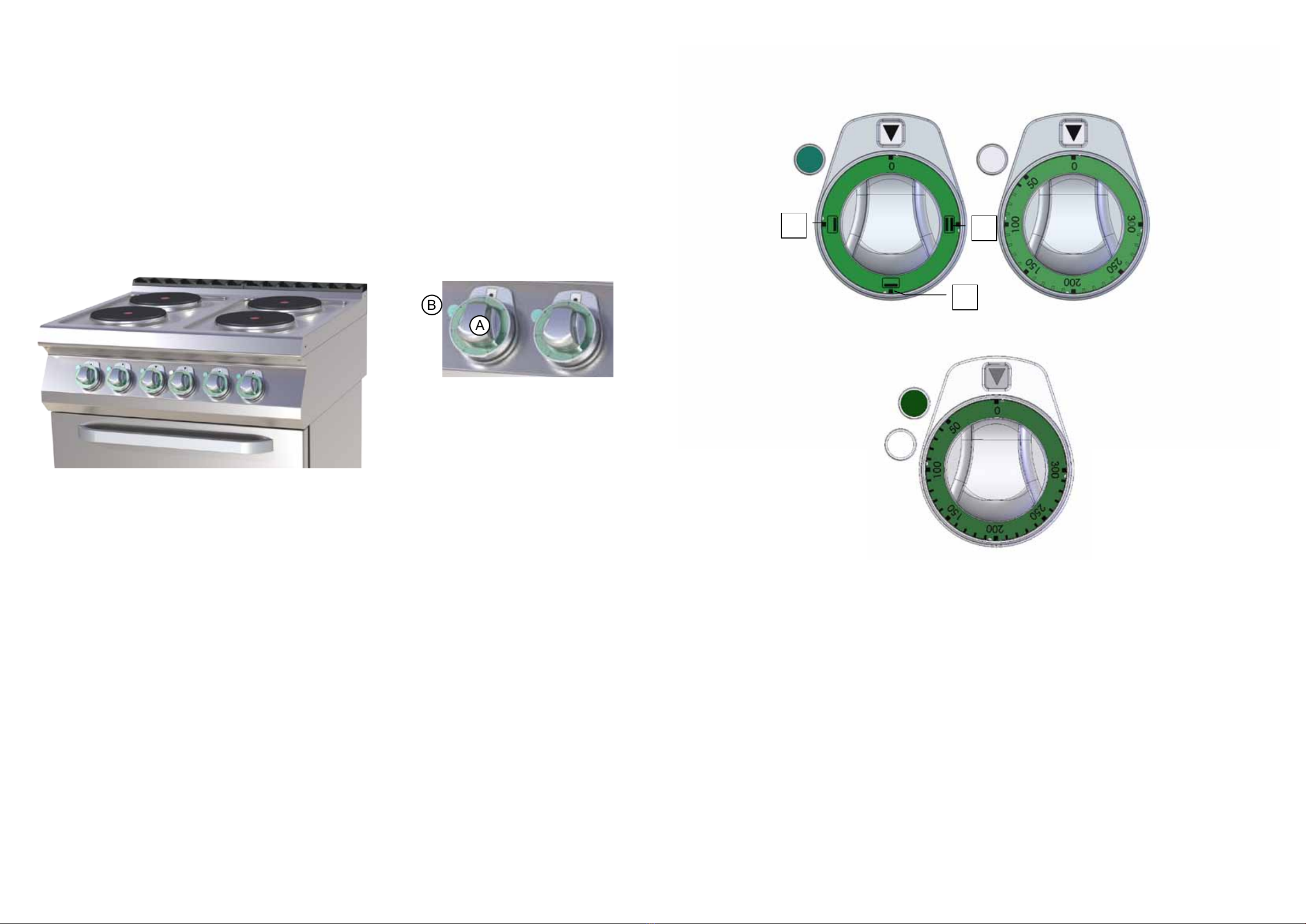
Turn the knob (A) and adjust required performance. Pilot lamp (B) will light. Pilot lamp (B) lights when the
device is connected to the electricity and switched on. Switch the device off by turning the knob (A) into
position „0“.
MAINTENANCE
We recommend to have the device checked once a year by the professional service. Only qualifi ed or
competent persons can do interventions in the product. Comments and recommendation. Use the device
only under supervision.
A
B
Control of the electic oven (STATIC)
You can choose to switch the control knob into select position for top and bottom heaters at the
same time (position 1), or just the bottom heater (position 3) or upper heater (position 2). This is
indicated by green LED. Set the control knob into desired temperature. Working heater is indicated
by orange LED, when light goes off, the oven is preheated to the requested temperature. Turn off
the oven by turning both knobs to „0“.
Control of the convection oven
Turn the control knob to the right, will turn on the fan. This is signalized with a green LED. After
that, set the control knob into desired temperature. Working of the heater is indicated by orange
LED, when light goes off, the oven is preheated to the desired temperature. Turn off the oven by
turning left into the "0".
3
1
2
CONTROLS
Regulation knob of burnen Regulation knob of gas oven
Switcher of static oven Regulation knob of static oven
1
2
3
SWITCH OFF
IGNITION
TEMPERATURE
Regulation knob of convection oven
8 9
8
CLEANING AND MAINTENANCE
ATTENTION! The device cannot be cleaned by direct or pressure water. Clean it daily. Daily maintenance
keeps longer useful life and effi ciency of the device. Before cleaning make sure to have disconnected the
device from electricity. Always switch off the main feeder to the device. Stainless parts wash with moist
cleaning cloth and non abrasive detergent than dry it by the cloth. Do not use abrasive and corrosive
detergents. All food residues must be removed from the surface, you can use scraper.
!!! YOU MUST LUBRICATE THE TOP WITH VEGETABLE OIL AFTER EACH CLEANING !!!
WHAT TO DO IN CASE OF BREAK-DOWN
Switch off the electric feeder and call seller´s professional service.
INDICATION
Guarantee does not cover all consumption parts succumable to common wear (rubber seals, bulbs, glass and
plastic parts etc.). The guarantee does not refer to the devices which were not installed in correspondence with
instructions - by qualifi ed worker, in conformity with standards and when somebody handled incompetently
the device (interventions into inner equipment) or the device was operated by non qualifi ed staff or at variance
with instructions for use. Guarantee does not also cover the damages caused due to infl uence of nature or
other outer intervention.
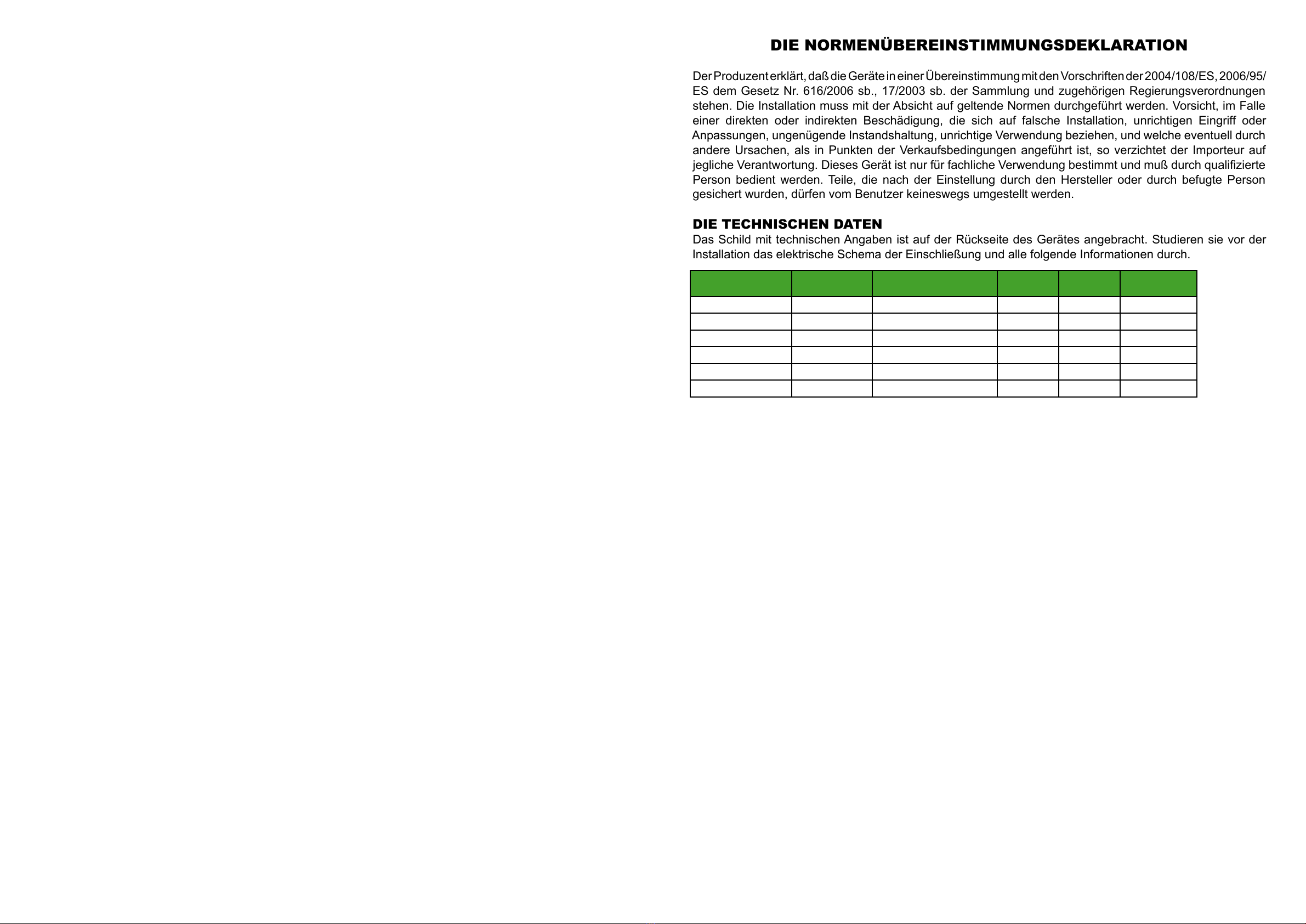
DIE NORMENÜBEREINSTIMMUNGSDEKLARATION
DerProduzent erklärt,daß dieGerätein einerÜbereinstimmung mitden Vorschriften der2004/108/ES,2006/95/
ES dem Gesetz Nr. 616/2006 sb., 17/2003 sb. der Sammlung und zugehörigen Regierungsverordnungen
stehen. Die Installation muss mit der Absicht auf geltende Normen durchgeführt werden. Vorsicht, im Falle
einer direkten oder indirekten Beschädigung, die sich auf falsche Installation, unrichtigen Eingriff oder
Anpassungen, ungenügende Instandshaltung, unrichtige Verwendung beziehen, und welche eventuell durch
andere Ursachen, als in Punkten der Verkaufsbedingungen angeführt ist, so verzichtet der Importeur auf
jegliche Verantwortung. Dieses Gerät ist nur für fachliche Verwendung bestimmt und muß durch qualifi zierte
Person bedient werden. Teile, die nach der Einstellung durch den Hersteller oder durch befugte Person
gesichert wurden, dürfen vom Benutzer keineswegs umgestellt werden.
DIE TECHNISCHEN DATEN
Das Schild mit technischen Angaben ist auf der Rückseite des Gerätes angebracht. Studieren sie vor der
Installation das elektrische Schema der Einschließung und alle folgende Informationen durch.
9
DIE VERPACKUNGS-, UND VORRICHTUNGSKONTROLLE
Die Vorrichtung verlässt unsere Lager in ordentlicher Verpackung, auf deren die entsprechenden Symbole
und Bezeichnungen stehen. In der Verpackung befi ndet sich entsprechende Bedienungsanweisung. Falls die
Verpackung eine schlechte Behandlung oder Anzeichen der Beschädigungen vorweist, muß dieses sofort
beim Transporteur reklamiert werden und zwar durch Unterzeichnung eines Schadensprotokolles.
Wichtige Hinweise
• Nur für professionellen Verbrauch geeignet
• Diese Bediennungsanleitung muss ordentlich und bedächtig gelesen werden, weil sie wichtige Informationen
über Sicherheitsmerkmale, Installation und Anwendung beinhaltet
• Diese Empfehlungen beziehen auf diesen Produkt
• Der Produkt entspricht geltenden Normen
• Diese Anleitung muß ordentlich für die zukünftige Verwendung hinterlegt werden
• Hindern Sie den Kinder an Vorrichtungsmanipulation
• Beim Verkauf oder Verlegung ist es notwendig sich zu überzeugen, daß die Bedienstperson oder Fachservis
sich mit der Behherrschung und Installationsanweisung in beiligender Anleitung, anvertraut gemacht haben.
• Das Produkt darf nur eingeschulte Bedienung bedienen
• Das Produkt darf nicht ohne Aufsicht ins Betrieb gesetzt sein
• Es ist empfohlen, minimal einmal pro Jahr eine Fachkontrolle durchführen zu lassen
• Bei eventueller Reparatur der Teilenumtauschungen müssen ausschließlich Originalteile angewendet
werden
• Das Produkt darf nicht durch einen Wasserstrahl oder Druckbrause gereinigt werden
• Schalten Sie alle Leitungen (Wasser, Elektrizität, Gas) bei einer Störung oder beim schlechten Lauf aus und
rufen Sie authorisierten Service an
• Der Hersteller verzichtet auf jegliche Verantwortung bei Störungen, die durch fehlerhafte Installation,
Nichteinhaltung o.a. Empfehlungen, andere Verwendung u.ä, verursacht wurden
TYPE DE
PRODUIT TENSION (V/HZ) NOMBRE DE THER-
MOSTATS (UNITÉS)
PUISSANCE
MAX. (KW) DIMENSION (CM) DIMENSION DE LA CHAMBRE
(CM)
B - 4 400 V, 3N, 50 Hz 2 4,8 95 x 91 x 41 v 70 x 70 x 15 v
B - 6 400 V, 3N, 50 Hz 2 7,2 95 x 121 x 41 v 70 x 105 x 15 v
B - 8 400 V, 3N, 50 HZ 49,6 95 x 91 x 76 v 2x 70 x 70 x 15 v
B - 12 400 V, 3N, 50 HZ 414,4 95 x 121 x 76 v 2x 70 x 105 x 15 v
B - 4/50 400 / 3N / 50 Hz 2 477,5 x 71 x 38 52 x 52 x 15 v
B - 8/50 400 / 3N / 50 Hz 46 77,5 x 71 x 51 2x 52 x 52 x 15 v
MODEL SPANNUNG
(V/HZ)
ANSCHLUSSWERT
(kW)
PLATTE
(kW)
BACKOFEN
(kW)
ABMESSUNGEN
(cm)
SPT-780-21 E 400/3N/50 16,7 4 x 2,6 6,3 80x73x90 h
SPQT-780-21 E 400/3N/50 16,7 4 x 2,6 6,3 80x73x90 h
SPT-780-11 E 400/3N/50 13,53 4 x 2,6 3,13 80x73x90 h
SPQT-780-11 E 400/3N/50 13,53 4 x 2,6 3,13 80x73x90 h
SPT-7120-21 E 400/3N/50 21,9 6 x 2,6 6,3 120x73x90 h
SPQT-7120-21 E 400/3N/50 21,9 6 x 2,6 6,3 120x73x90 h

10 11
10
DIE PLATZIERUNG
Es ist unbedingt notwendig, zu der Regulation der Gerätetätigkeit, daß das Milieu - der Küche -, wo das Gerät
installiert wird, sehr gut belüftbar ist (im Hinblick darauf: sei der Techniker sich mit geltenden Normen (EN)
richtet). Wenn die Einrichtung so plaziert wird, daß sie im Mobiliarwandkontakt stehen wird, so müssen diese
einer Temperatur von 90°C wiederstehen. Die Installation, Herrichtung, Inbetriebsnahme müssen durch
qualifi zierte Person, die zu solchen Vorkehrungen eine Befugnis hat und dies laut geltenden Normen nach,
durchgeführt werden.
Packen Sie das Gerät aus und kontrollieren Sie , ob sich das Gerät während des Transportes nicht beschädigt
hat. Platzieren Sie das Gerät auf eine waagrechte Fläche (maximalle Unebenheit bis 2°). Stellen Sie das
Gerät unter den Haubenabzug, damit Sie die Wasserdämpfe und den Geruch eliminieren. Das Gerät kann
selbständig oder in einer Reihe mit Geräten unserer Herrstellung installiert werden. Es ist notwendig die
minimale Entfernung von 10 cm zu anderen Gegenständen einzuhalten, so dass die Wärmeisollierung der
brennbaren Teilen gewährleistet wird.
Das Gerät kann selbständig oder in einer Reihe mit Geräten unserer Herrstellung installiert werden. Es
ist notwendig die minimale Entfernung von 10 cm zu anderen Gegenständen einzuhalten, so dass die
Wärmeisollierung der brennbaren Teilen gewährleistet wird.
TECHNISCHE HINWEISE ZUR INSTALLATION UND REGELUNG
Wichtig:
Zur Benützung AUSSCHLIEßLICH nur für spezialisierte Techniker
Instruktionen, die folgen, wenden sich an den Techniker, der für die Installation qualifi ziert ist, damit er alle
Operationen mit der korrektesten Weise und laut der gültigen Normen durchführt.
Wichtig
Jeweils irgendeine Tätigkeit, die mit der Regulation verbunden ist u.ä, muß nur mit der aus dem Netz
ausgezogenen und abgeschalteten Einrichtung vollgezogen sein.
Solange das Gerät unter der Spannung notwendig zu halten ist, eine höchste Vorsicht zu beachten vorliegt.
DER ELEKTRISCHE KABELNETZANSCHLUSS
Die Installation der elektrischen Ankupplung - Diese Zuleitung muß selbstständig gesichert werden. Und das
durch entsprechende Sicherung des Nennstromes in der Abhängigkeit am Anschlußwert des installierten
Gerätes. Kontrollieren sie den Anschlußwert des Apparates auf dem Produktionsschild im Hinterteil des
Gerätes. Schließen Sie das Gerät direkt ans Netz an.
Es ist unbedingt notwendig zwischen das Gerät und das Netz einen Schalter zu legen, der eine minimale
Entfernung von 3mm unter den Einzelkontakten aufweist und der auch den geltenden Normen und
Belastungen entspricht. Die Erdungszuleitung (gelbgrün) darf nicht durch diesen Schalter unterbrochen sein.
Der Zuleitungskabel muß in jedem Fall so angebracht sein, dass er in keinem Punkt einer um 50°C höherer
Temperatur als Umgebungstemperatur nicht erreicht. Eher das Gerät ans Netz angeschlossen wird, versichern
Sie sich, dass:
• die Zuleitungssicherung und die Innenscheidung die Einrichtungsbelastung ertragen (siehe Matrizeschild),
• die Verteilung mit wirksamer Erdung laut Normen (EN) und Gesetzbedingungen ausgestattet ist
WIR VERZICHTEN AUF JEGLICHE VERANTWORTUNG IM FALLE, DASS DIESE NORMEN NICHT
RESPEKTIERT WERDEN UND IM FALLE DER NICHTEINHALTUNG DER OBENERWÄHNTER
GRUNDSÄTZE.
Es ist notwendig die Schutzfollie vor der ersten Benützung zu beseitigen, sowie das Gerät zu reinigen siehe
das Kapitel „Reinigung und Instandshaltung“.
DIE SICHERHEITSVORRICHTUNGEN AUS DER SICHT DES
FEUERSCHUTZES LAUT EN. 061008 ČL. 21
Die Einrichtungsbedienung dürfen nur Erwachsene ausführen
• Das Gerät darf sicher in gewöhnlicher Umgebung laut EN 332000-4-482; EN 332000-4-42
verwendet werden.
• Es ist notwendig das Gerät so platzieren, daß es auf einer unbrennbaren Grundlage steht oder hängt.
• Es dürfen, auf und in eine Entfernung, die kleinerermase als sicher vom Gerät bezeichnet wird, keine
Gegenstände aus brennbaren Materilien (die kleinste Entfernung vom Brennbarem ist 10 cm) aufgestellt
werden.
• Die sicheren Entfernungen von Massen der einzelnen Brenngra
Tabelle:
Baumassefeuerbrenngrad ins Brenngrad (EN) der Massen und Produkte eingegliedert
A Unbrennbar Granit, Sandstein, beton, Ziegel, Keramikbekleidung, Putz
B nicht einfach brennbar Akumin, Heraklit, Lihnos, Itaver
C1 schwer brennbar Holz, Laubbaum, Furnier Sirkoklit, Festpapier, Umakart
C2 mittel brennbar Holzspanplatten, Solodur, Korkplatten, Hartgummi, Bodenbeläge
C3 leicht brennbar Holzfaserplatten, Polystyren, Polyureten, PVC
Die Bedarfsartikel müssen sicher installiert werden und sind mit regulierenbaren Beinchen - zur Ausgleichen
der Höhe und der Unebenheiten eingestattet.
Die Geräte müssen in einer sicheren Weise installiert werden. Bei der Installation müssen weiter betreffende
Projekt-, Sicherheits-, und Hygienevorschriften respektiert werden.
• EN 06 1008 Feuerschutz der örtlichen Geräte und der Wärmquellen
• EN 33 2000 (33 2000-4-482; 33 2000-4-42) Umgebung für elektrische Geräte
Gasversorgung -Gasleitunge in Gebäuden - Höchste Verkehrsdruck ≤ 5 BarVerkehrsansprüche,
• § 10 des Gesetzes Nr.185/2001 Sb., der Abfälle betrifft.
12 13
12
GEBRAUCHSANWEISUNG
IVorsicht!
Bevor Sie das Gerät verwenden werden, ist es notwendig ihn gut mit feuchtem Lappen abzuwaschen. Lassen
Sie nie das Gerät ohne Aufsicht im Betrieb.
Drehen Sie mit dem Beherrschenrädchen (A) und stellen Sie die verlangte Temperatur ein. Die Kontrollleucht
(B) wird scheinen. Die Kontrolllampe (B) scheint, wenn das Gerät unter Elektrostrom steht. Das Gerät schalten
Sie so aus, wenn Sie das Beherrschenrädchen (A) in die Lage „0“ umdrehen.
INSTANDSHALTUNG
Es ist empfohlen mindestens einmal pro Jahr das Gerät durch einen fachlichen Servicedienst warten zu
lassen. Alle Eingriffe in das Gerät darf nur eine qualifi zierte Person durchführen, die zu solchen Handlungen
eine Befugnis besitzt.
A
B
CONTROLLING DER STATISCHEN OFEN
Sie können den Regler in ausgewählte Positionen Schalter für oberen und unteren Heizkörper zur
gleichen Zeit (Position 1), oder einfach nur die Bodenheizung (Position 3) oder obere Heizung (Posi-
tion 2). Dies wird durch grüne LED angezeigt. Stellen Sie den Regler in die gewünschte Temperatur.
Arbeiten Heizung durch orange LED, wenn das Licht erlischt angegeben ist, wird der Ofen auf die
gewünschte Temperatur vorgeheizt. Schalten Sie den Ofen durch Drehen der beiden Knöpfe auf „0“.
CONTROLLING DER UMLUFTOFEN
Drehen Sie den Regler nach rechts drehen, wird auf dem Ventilator einzuschalten. Dies wird durch
eine grüne LED signalisiert. Danach stellen Sie den Drehknopf in die gewünschte Temperatur. Ar-
beiten der Heizung wird durch die orange LED, wenn das Licht erlischt angedeutet, wird der Ofen
auf die gewünschte Temperatur vorgeheizt. Schalten Sie den Ofen nach links in die „0“ nach links.
Achtung!: -Bei eingeschaltetem Backofen darf dessen Tür nicht offen bleiben, da
sonst die Drehknöpfe überhitzt und beschädigt werden könnten.
3
1
2
KONTROLLEN
Brenner Drehknopf Verordnung Knopf des Gas-Backofen
Switcher von statischen Ofen Verordnung Knopf statischer Backofen
1
2
3
Ausschaltet
Anzünden
Temperatureinstellung
Verordnung Knopf Heißluftofen

14 15
14
INSTANDSHALTUNG
Es ist empfohlen mindestens einmal pro Jahr das Gerät durch einen fachlichen Servicedienst warten zu
lassen. Alle Eingriffe in das Gerät darf nur eine qualifi zierte Person durchführen, die zu solchen Handlungen
eine Befugnis besitzt.
!!! Nach jedem Reinigungsausrüstung nötig ist, die Oberfl äche der Arbeitsplatte mit Pfl anzenöl!!!
Bemerkunge und Empfehlunge
Benützen Sie das Gerär nur unter ständigen Aufsicht.
DIE REINIGUNG UND INSTANDSHALTUNG
ACHTUNG! Die Einrichtung darf nicht mit Direkt-, oder Druckwasserstrahl gereinigt werden. Reinigen Sie
das Gerät täglich. Die Lebensdauer und Gerätewirkung wird durch die tägliche Wartung gewährleistet.
Überzeugen Sie sich, vorm Reinigungsanfang, dass Sie die Einrichtung vom Elektrostrom abgeschaltet haben.
Schalten Sie immer die Gerätehauptzufuhr ab. Waschen Sie die Edelstahteile mit feuchtem Waschlappen,
der im Waschpulver getauft ist und keine grobe Teilchen aufweist. Wischen Sie alles ins Trockene ab.
Verwenden Sie keine abrasive- oder korrosionsreiche Reinigungsmitteln. Alle Speisenreste müssen von der
Arbeitsplatte beiseitigt werden. Sie könnem eine Spachtel benützen. Nach jeder Gerätereinigung müssen
Sie die Grillplatten mit Pfl anzenöl aufreiben.
WIE MAN IM FALLE EINER STÖRUNG VORANGEHEN SOLL
Schalten sie die elektrische Stromleitung ab und rufen die Serviceorganisation des Verkäufers an.
HINWEIS
Die Garantie bezieht sich nicht auf alle Vebrauchsteile, die der geläufi ger Abnutzung unterstehen (gesamte
Gummidichtungen, Glühlampen, alle glasernde und plastiche Teile, usw.). Die Garantie bezieht sich nicht
weiterhin auf Einrichtungen, die durch befugte Person laut Anweisung und entsprechender Normen nicht
installiert worden sind und wenn mit dem Gerät unfachmänisch manipuliert wurde (Eingriffe ins Innere) und
auf Beschädigungen durch Natureinfl üsse oder Ausseneingriffe.
15
DÉCLARATION DE CONFORMITÉ
Le fabricant certifi e la conformité des appareils aux normes 2004/108/ES, 2006/95/ES, 2006/95/ES à la
loi n° 616/2006 sb., 17/2003 sb. et aux décrets applicables. L‘installation doit être effectuée dans le respect
des normes en vigueur. Attention: le fabricant décline toute responsabilité en cas de dommages, directs ou
indirects, causés par une mauvaise installation, par une utilisation, des interventions ou des modifi cations
impropres, par un entretien insuffi sant, ainsi qu‘en cas de dommages dérivant des causes mentionnées
dans les conditions de vente. L‘appareil objet de la présente notice est prévu pour un usage professionnel,
aussi son utilisation doit-elle être confi ée à un personnel possédant les compétences nécessaires à cet
effet. L‘utilisateur ne doit procéder à aucune intervention ni à aucune modifi cation sur les parties réglées et
protégées par le fabricant ou autre personnel autorisé à cet effet.
CARACTÉRISTIQUES TECHNIQUES
L‘étiquette sur laquelle fi gurent les caractéristiques techniques est apposée sur la partie postérieure de
l‘appareil. Avant de procéder à l‘installation, prendre connaissance du schéma électrique et de toutes les
informations que contient la présente notice.
CONTROLE DE L‘EMBALLAGE ET DE L‘APPAREIL
En vue de son transport, l‘appareil quitte les établissements du fabricant parfaitement emballé (sur l‘emballage
sont apposés les étiquettes et les symboles nécessaires à cet effet). L‘emballage contient également la
notice des instructions d‘utilisation. Dans le cas où l‘emballage présenterait des dommages ainsi que dans
le cas où il s‘avérerait qu‘il a été manipulé sans les précautions nécessaires, il est impératif d‘adresser sans
attendre une déclaration au transporteur en y joignant une acceptation de la marchandise sous réserve.
Recommandation importante:
• Pour usage professionnel seulement
• La présente notice des instructions d‘utilisation et d‘entretien contient d‘importantes informations relatives à
la sécurité, à l‘installation et à l‘utilisation; il est nécessaire d‘en effectuer attentivement la lecture.
• Les recommandations se réfèrent à l‘appareil objet de la présent notice.
• L‘appareil est conforme aux normes en vigueur.
• Veiller à bien conserver la notice de telle sorte qu‘elle puisse être consultée à tout moment en cas de besoin.
• Ne pas laisser des enfants s‘approcher de l‘appareil durant son utilisation.
• Pendant la vente ou après le déménagement de l’appareil vérifi er que le personnel lise attentivement la
présente notice d’utilisation
• L’appareil ne peut être utilisé que par le personnel instruit
• L’appareil ne peut être laissé en marche sans surveillance
• Il est recomandé de faire l’appareil controller au moins une fois par an dans un service spécialisé
• Ne pas utiliser que des pièces détachées originelles.
• En cas de défaut ou de mavaise fonction, débrancher l’appareil (eau, gaz, électricité) et appeler un service
spécialisé
• Le fabricant décline toute responsabilité en cas de dommages, directs ou indirects, causés par une mauvaise
installation, utilisation , etc
MODEL TENSION
(V/HZ)
PUISSANCE
(KW)
PLAQUES
(KW)
AVEC FOUR
(KW)
DIMENSIONS
(CM)
SPT-780-21 E 400/3N/50 16,7 4 x 2,6 6,3 80x73x90 h
SPQT-780-21 E 400/3N/50 16,7 4 x 2,6 6,3 80x73x90 h
SPT-780-11 E 400/3N/50 13,53 4 x 2,6 3,13 80x73x90 h
SPQT-780-11 E 400/3N/50 13,53 4 x 2,6 3,13 80x73x90 h
SPT-7120-21 E 400/3N/50 21,9 6 x 2,6 6,3 120x73x90 h
SPQT-7120-21 E 400/3N/50 21,9 6 x 2,6 6,3 120x73x90 h

16 17
16
LA LOCATION
Le local dans lequel l‘appareil est installé doit être bien ventilé. Si l’appareil doit toucher le parois , celui-ci
doit résister à la chaleur de 90°C au minimum. L’installation, le réglage et la mise en marche doivent être
effectués par une personne qualifi ée ayant une autorisation nécessaire selon les normes en vigueur.
Déballez l’appareil et vérifi ez s’il n’était pas endomagé pendant le transport. Placez l’appareil sur une surface
horizontale (pente maximale de 2°). Placez l’appareil sous une hotte pour éliminer la vapeur et mauvaise
odeur.
L’appareil peut être installé seul ou en série avec d’autres appareils de notre fabrication. Il faut respecter la
distance minimale de 10 cm entre l’appareil et d’autres objets ainsi qu’éviter le contact avec les matériaux
infl ammables. Dans ce cas il faut prévoir les arrangements nécessaires pour assurer la protection des parties
infl ammables.
INSTRUCTIONS TECHNIQUES POUR INSTALLATION ET REGLEMENT
Important:
Le fabricant ne fournit pas de garantie pour les défauts causés par l‘usage, tout manquement impropre
aux instructions contenues dans les instructions ci-jointes pour l‘utilisation et aux mauvais traitements des
appareils.
Installation, réglage et réparation d‘appareils pour les cuisines, ainsi que leur élimination en raison de
dommages possibles au gaz peut être effectuée qu‘en vertu d‘un contrat de maintenance, ce contrat peut
être signé avec un distributeur agréé, et doivent être conformes à la réglementation technique et normes et
réglementations concernant l‘installation, l‘alimentation, de raccordement de gaz et de la santé et la sécurité
du système.
Ces instructions sont destinées au technicien qualifi é qui doit effectuer l‘installation, le mettre en marche et
tester l‘appareil.
Toute activité en tant que paramètres, le placement, le rééquilibrage etc, doit être faite que lorsqu‘il est
périphérique déconnecté de l‘électricité. Si il est nécessaire d‘avoir le périphérique connecté à l‘électricité,
vous devez garder la plus grande attention afi n d‘éviter toute blessure.
BRANCHEMENT ÉLECTRIQUE
Istallation de prise de courant – La prise de courant doit avoir un coupe-circuit indépendant en dépendance
de puissance fournie de l’appareil. Vérifi ez la puissance de l’appareil sur la plaque des caractéristiques
techniques.
Branchez l’appareil directement au réseau, il faut mettre un interrupteur entre le réseau et l’appareil, son
ouverture de contacts étant 3 mm au minimum. Câble de terre (vert-jaune) ne peut pas être interrompu par
cet interrupteur. En tout cas, le câble de prise de courant doit être placé de telle manière que sa température
ne surpasse jamais la température du milieu de plus que 50°C. Avant le branchement au réseau, s’assurer
que :
- le coupe-circuit et distribution intérieure peuvent endurer la charge de l’appareil (voir la plaque)
- la mise à la terre fonctionne selon les normes en vigueuer (EN) et selon la loi
- la prise ou l’interrupteur de circuit sont faciles d’accès
Le fabricant rénonce à toute résponsabilité en cas que les normes ne seront pas respectés ainsi qu’en cas
de dérogation des règles mentionnés ci-haut.
Avant la première utilisation, il faut rétirer le fi lm de protection et nettoyer l’appareil – voir chapitre «
nettoyage et entretien ».
Entretien:
Il est recommandé de faire controller l’appareil dans un service spécialisé au moins une fois par an. Toutes
les interventions peuvent être effectuées seulement par une personne qualifi ée ayante une autorisation pour
ces interventions.
17
MÉSURES DE SÉCURITÉ POUR LA PROTECTION CONTRE INCENDIE SELON EN
06 1008 ARTICLE 21:
- l’apparel ne peut être utilisé que par des personnes majeures
- l’appareil peut être utilisé dans un espace ordinaire selon EN 332000-4-482; 332000-4-42
- l’appareil doit être placé ou suspendu d’une manière stable sur une surface ininfl ammable
Il est interdit de placer sur l’appareil ou dans la distance inférieure à 10 cm de l’appareil des objets infl ammables.
- les distances de sécurité pour les matériaux infl ammables selon leurs degré d’infl ammabilité et les
informations sur l’infl ammabilité des matériaux de construction – voir le tableau
Tableau:
degré d’infl ammabilité d’un matériel de construction (EN 730823)
A ininfl ammables granit, grès, béton, briques, carrelage céramique, enduit
B diffi cilement infl ammables acumin, héraclite, lihnos, itaver
C1 mal infl ammables bois des arbres feillus, contre-plaqué, papier durci, umakart
C2 infl ammabilité moyenne aggloméré, solodur, liège, caoutchouc, revêtements
C3 infl ammabilité facile planches de fi bre de bois, polystyrène, polyurethène, PVC
L’appareil doit être instalé d’une manière sûre. Pour l’ajustage de l’appareil est ce-ci procuré des pieds
réglables.
• EN 06 1008 protection contre incendie des consommateurs d’énergie locaux et des émmeteurs de chaleur
• EN 33 2000 (33 2000-4-482; 33 2000-4-42) le milieu pour les appareil électriques

18 19
18
MODE D’EMPLOI
Attention !
Avant la première utilisation, il faut laver l’appareil à l’aide d’un torchon humide et d’un détergent. Rincer et
sécher.
Avant la 1ere mise en route retirer la feuille de protection. Nettoyer toutes les surfaces á l’aide d’un chiffon
doux, d’eau tiède et d’un détergent, de façon á éliminer les produits antirouille appliqués durant la fabrication
et essuyer ensuite l’appareil á l’aide d’un chiffon propre.
OBSERVATIONS ET RECOMMANDATIONS
Tournez le bouton de réglage (A) afi n d’ajuster la puissance démadée. Le voyant vert (B) va être alumé. Le
voyant vert (B) est alumé si l’appareil est sous tension. Pour débrancher l’appareil retournez le bouton de
réglage (A) à la position “0”.
MAINTENANCE
Il est conseillé de faire controler l’appareil au moins une fois par an par un eservice spécialisé. Tous les
intervetions dans l’apareil peuvent être effectuées uniquement par une personne qualifi é, possedante
l’autorisation á telles opérations.
A
B
CONTRÔLE DE LA FOUR STATIQUE
Vous pouvez basculer le contrôleur dans des positions choisies pour la partie supérieure et inférieure
des éléments chauffants dans le même temps (position 1), ou chauffage par le sol tout simplement
(position 3) ou de chauffage supérieure (position 2). Ceci est indiqué par la LED verte. Tournez le bou-
ton à la température désirée. Installations de chauffage par LED orange lorsque la lumière s‘éteint est
spécifi é, le four est préchauffé à la température désirée. Éteindre le four en tournant les boutons à „0“.
CONTRÔLE DE L‘ÉTUVE À AIR
Tournez, tournez le bouton vers la droite, tournez le ventilateur. Ceci est indiqué par une LED verte.
Puis tournez le bouton à la température désirée. Travail du chauffage se fait par la LED orange indique
quand la lumière s‘éteint, le four est préchauffé à la température désirée. Allumez le four vers
la gauche dans le „0“ à la gauche.
Attention!: Lorsque le four est allumé, la porte ne doit en aucun cas rester ouverte pour ne pas ris-
quer de chauffer et d‘endommager les commandes.
3
1
2
CONTRÔLES
Bouton du brûleur Bouton de réglage du four à gaz
Switcher par four statique Règlement bouton four statique
1
2
3
OFF
IGNITION
Le réglage de température
Règlement bouton Four à convection
20 21
20
NETTOYAGE ET ENTRETIEN
ATTENTION! Le nettoyage au jet d’eau ou sous pression n’est pas autorisé.
Nettoyer l’appareillage tous les jour. Le nettoyage quotidien prolonge la durée de service et l’effi cacité
d’appareillage. Avant d’effectuer toute entretien, il faut débrancher l’appareil du réseau électrique. Les parties
en inox doivent être nettoyées avec un chiffon humide, à l’aide d’un détergente liquide, non abrasif et ensuite
être bien essuyées. Pour eliminer les reliefs du plan de travaille, il est possible d’utiliser une spatule.
Comment procéder en cas d’une panne
Débrancher la prise du cordon secteur et contacter le service après-vente du revendeur.
MAINTENANCE
Il est conseillé de faire controler l’appareil au moins une fois par an par un service spécialisé. Tous les
intervetions dans l’apareil peuvent être effectuées uniquement par une personne qualifi é, possedante
l’autorisation á telles opérations
!!! AFIN D’ÉVITER LA FORMATION DE ROUILLE, IL FAUT TRAITER LA SURFACE AVEC UNE HUILE
VÉGÉTALE APRÈS CHAQUE NETTOYAGE !!!!!!
AVERTISSEMENT
La garantie ne couvert pas de pièces soumises á l’usure normale (étanchements en caoutchouc, lampes,
pièces plastiques et en verre, etc.) ainsi que l’appareillage dont l’installation n’a pas été exécuté conformément
á la mode d’emplois, par une personne qualifi ée et conformément aux normes correspondantes. La garantie
ne couvert pas de dommages causées par une manipulation non autorisée (interventions dans l’appareillage
intérieure) ou si l’appareil était servit par des personnes non qualifi ées et/ou en cas de non-respect des
instructions du manuel d’utilisation. La garantie ne couvert pas de dégâts causées par des actions naturelles
ou par d’autres infl uences extérieures.
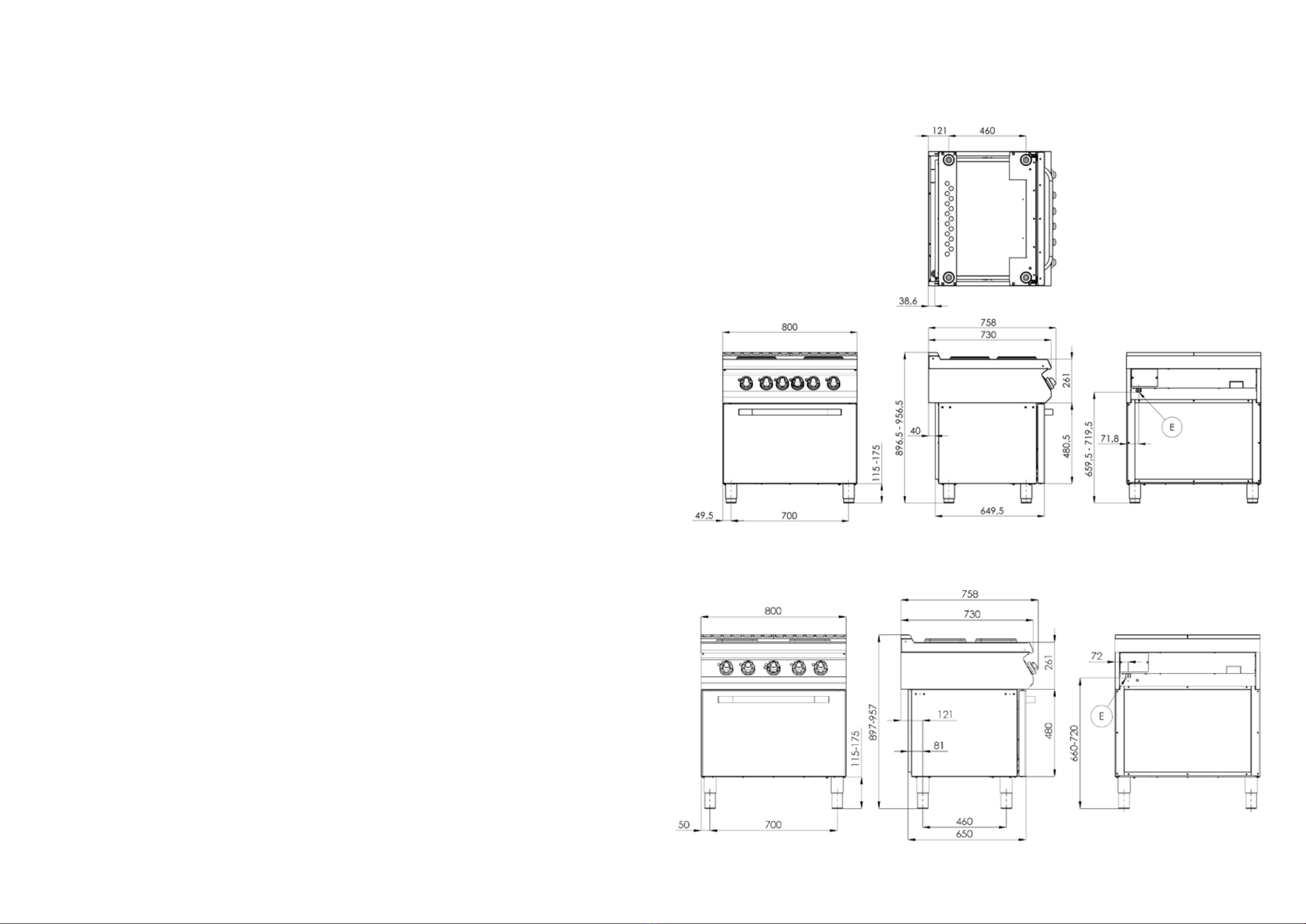
DIMENSION PLANS / MASSSKIZZEN / DIMENSIONS
21
SPT-780-21 E / SPQT-780-21 E
SPT-780-11 E / SPQT-780-11 E

22 23
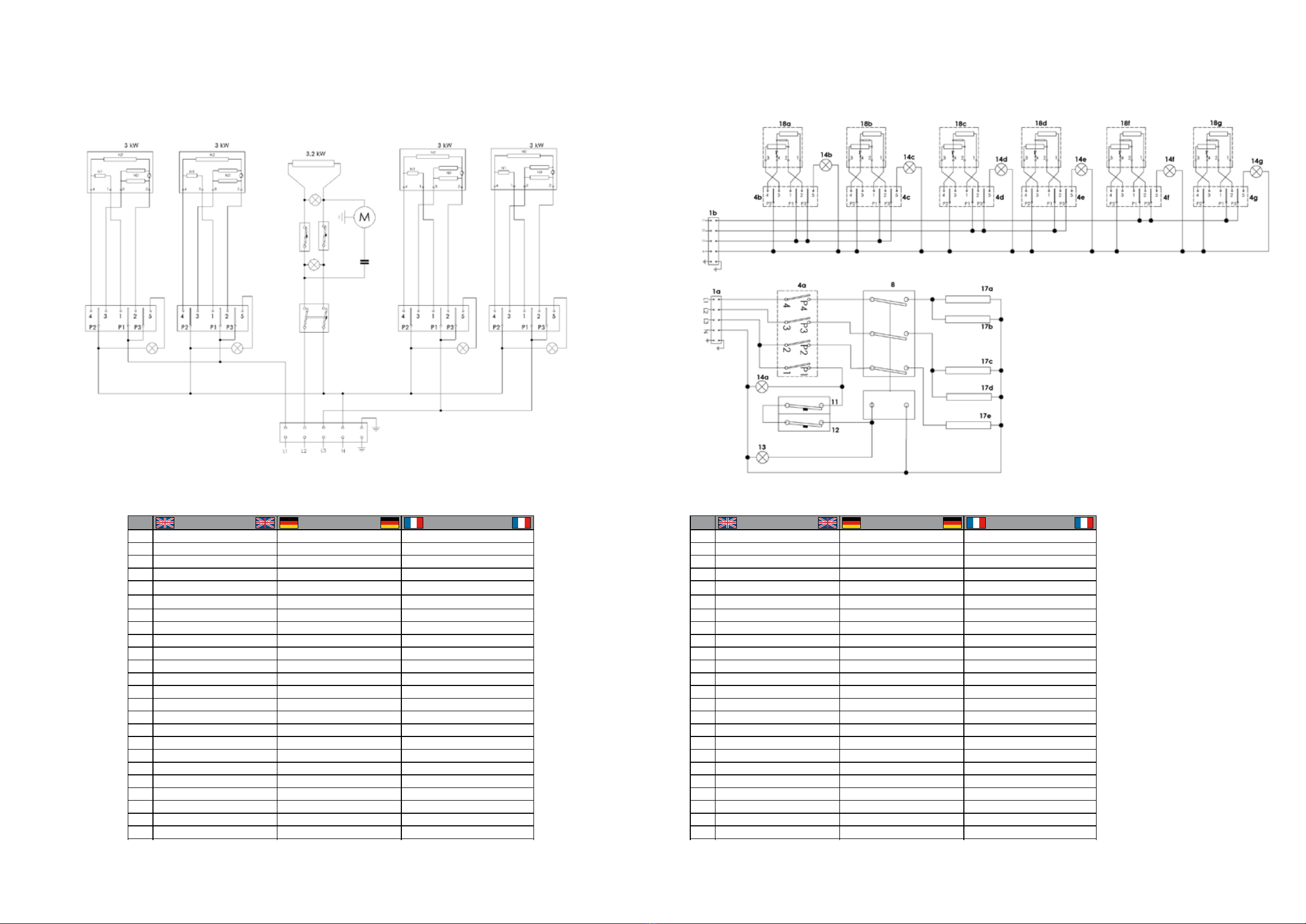
EL. CONNECTION DIAGRAM / SCHALTPLAN / SCHÉMA DU ELECTRIQUE
SPT-780-21 E / SPQT-780-21 E
23
ENGLISH DEUTSCH FRANÇAIS
1 TERMINAL TERMINAL TERMINAL
2 SWITCH O / I SWITCH O / I INTERRUPTEUR O / I
3 ILLUMINATED SWITCH O / I BELEUCHTETE SWITCH O / I INTERRUPTEUR ILLUMINÉ O / I
4ROTARY SWITCH SWITCH ROTARY SWITCH ROTARY
5 PUSH BUTTON SWITCHES DRUCKSCHALTER BOUTON POUSSOIR
6 LIMIT SWITCH ENDSCHALTER LIMIT SWITCH
7 MICROSWITCH MIKROSCHALTER MICRO
8 RELAY RELAY RELAIS
9 RELAY CONTACTS RELAISKONTAKTE CONTACTS DE RELAIS
10 TIMER TIMER TIMER
11 OPERATING THERMOSTAT THERMOSTAT WORK TRAVAIL DU THERMOSTAT
12 SAFETY THERMOSTAT SICHERHEIT THERMOSTAT THERMOSTAT DE SÉCURITÉ
13 WHITE LIGHT WEISSLICHT L'ORANGE
14 GREEN LIGHT GRÜNES LICHT LE VERT
15 DIODE DIODE DIODE
16 INTERIOR LIGHT INNENLEUCHTEN ECLAIRAGE INTERIEUR
17 HEATING ELEMENT HEIZELEMENT ELEMENT DE CHAUFFAGE
18 HOTPLATE HERDPLATTE PLAQUE CHAUFFANTE
19 TRANSFORMER TRANSFORMER TRANSFORMATEUR
20 FUSE FUSE FUSIBLE
20 RHEOSTAT RHEOSTAT RHEOSTAT
22 THERMOCOUPLE THERMOCOUPLE THERMOCOUPLE
23 SENSOR SENSOR CAPTEUR
24 MOTOR LIFT STROKE ENGINE MOTEUR DE COURSE
25 MOTOR FANS MOTOR FANS VENTILATEURS MOTEUR
26 STARTING CONDENSER AB CONDENSER À PARTIR CONDENSEUR
27 SPARK PLUG ZÜNDKERZE BOUGIE
28 GAS VALVE (SIT) GASVENTIL (SIT) VANNE DE GAZ (SIT)
29 SOCKET OUTLET SORTIE
30 DIGITAL THERMOMETER DIGITAL THERMOMETER THERMOMÈTRE NUMÉRIQUE
31 CONTROL UNIT STEUEREINHEIT UNITÉ DE CONTRÔLE
32 DIGITAL TIMER
SPT-7120-21 E / SPQT-7120-21 E
24 25
ENGLISH DEUTSCH FRANÇAIS
1 TERMINAL TERMINAL TERMINAL
2 SWITCH O / I SWITCH O / I INTERRUPTEUR O / I
3 ILLUMINATED SWITCH O / I BELEUCHTETE SWITCH O / I INTERRUPTEUR ILLUMINÉ O / I
4ROTARY SWITCH SWITCH ROTARY SWITCH ROTARY
5 PUSH BUTTON SWITCHES DRUCKSCHALTER BOUTON POUSSOIR
6 LIMIT SWITCH ENDSCHALTER LIMIT SWITCH
7 MICROSWITCH MIKROSCHALTER MICRO
8 RELAY RELAY RELAIS
9 RELAY CONTACTS RELAISKONTAKTE CONTACTS DE RELAIS
10 TIMER TIMER TIMER
11 OPERATING THERMOSTAT THERMOSTAT WORK TRAVAIL DU THERMOSTAT
12 SAFETY THERMOSTAT SICHERHEIT THERMOSTAT THERMOSTAT DE SÉCURITÉ
13 WHITE LIGHT WEISSLICHT L'ORANGE
14 GREEN LIGHT GRÜNES LICHT LE VERT
15 DIODE DIODE DIODE
16 INTERIOR LIGHT INNENLEUCHTEN ECLAIRAGE INTERIEUR
17 HEATING ELEMENT HEIZELEMENT ELEMENT DE CHAUFFAGE
18 HOTPLATE HERDPLATTE PLAQUE CHAUFFANTE
19 TRANSFORMER TRANSFORMER TRANSFORMATEUR
20 FUSE FUSE FUSIBLE
20 RHEOSTAT RHEOSTAT RHEOSTAT
22 THERMOCOUPLE THERMOCOUPLE THERMOCOUPLE
23 SENSOR SENSOR CAPTEUR
24 MOTOR LIFT STROKE ENGINE MOTEUR DE COURSE
25 MOTOR FANS MOTOR FANS VENTILATEURS MOTEUR
26 STARTING CONDENSER AB CONDENSER À PARTIR CONDENSEUR
27 SPARK PLUG ZÜNDKERZE BOUGIE
28 GAS VALVE (SIT) GASVENTIL (SIT) VANNE DE GAZ (SIT)
29 SOCKET OUTLET SORTIE
30 DIGITAL THERMOMETER DIGITAL THERMOMETER THERMOMÈTRE NUMÉRIQUE
31 CONTROL UNIT STEUEREINHEIT UNITÉ DE CONTRÔLE
32 DIGITAL TIMER
SPT-780-11 E / SPQT-780-11 E SPT-7120-21 E / SPQT-7120-21 E
ENGLISH DEUTSCH FRANÇAIS
1 TERMINAL TERMINAL TERMINAL
2 SWITCH O / I SWITCH O / I INTERRUPTEUR O / I
3 ILLUMINATED SWITCH O / I BELEUCHTETE SWITCH O / I INTERRUPTEUR ILLUMINÉ O / I
4ROTARY SWITCH SWITCH ROTARY SWITCH ROTARY
5 PUSH BUTTON SWITCHES DRUCKSCHALTER BOUTON POUSSOIR
6 LIMIT SWITCH ENDSCHALTER LIMIT SWITCH
7 MICROSWITCH MIKROSCHALTER MICRO
8 RELAY RELAY RELAIS
9 RELAY CONTACTS RELAISKONTAKTE CONTACTS DE RELAIS
10 TIMER TIMER TIMER
11 OPERATING THERMOSTAT THERMOSTAT WORK TRAVAIL DU THERMOSTAT
12 SAFETY THERMOSTAT SICHERHEIT THERMOSTAT THERMOSTAT DE SÉCURITÉ
13 WHITE LIGHT WEISSLICHT L'ORANGE
14 GREEN LIGHT GRÜNES LICHT LE VERT
15 DIODE DIODE DIODE
16 INTERIOR LIGHT INNENLEUCHTEN ECLAIRAGE INTERIEUR
17 HEATING ELEMENT HEIZELEMENT ELEMENT DE CHAUFFAGE
18 HOTPLATE HERDPLATTE PLAQUE CHAUFFANTE
19 TRANSFORMER TRANSFORMER TRANSFORMATEUR
20 FUSE FUSE FUSIBLE
20 RHEOSTAT RHEOSTAT RHEOSTAT
22 THERMOCOUPLE THERMOCOUPLE THERMOCOUPLE
23 SENSOR SENSOR CAPTEUR
24 MOTOR LIFT STROKE ENGINE MOTEUR DE COURSE
25 MOTOR FANS MOTOR FANS VENTILATEURS MOTEUR
26 STARTING CONDENSER AB CONDENSER À PARTIR CONDENSEUR
27 SPARK PLUG ZÜNDKERZE BOUGIE
28 GAS VALVE (SIT) GASVENTIL (SIT) VANNE DE GAZ (SIT)
29 SOCKET OUTLET SORTIE
30 DIGITAL THERMOMETER DIGITAL THERMOMETER THERMOMÈTRE NUMÉRIQUE
31 CONTROL UNIT STEUEREINHEIT UNITÉ DE CONTRÔLE
32 DIGITAL TIMER

26
This manual suits for next models
5
Table of contents
Languages:
Other RM Cooker manuals


Popular Cooker manuals by other brands

Beko
Beko S512 Installation & operating instructions and cooking guidance

PIMAK
PIMAK M018 user guide

M-system
M-system MAXI OVEN PRF 950 IX Instruction for the use - installation advice

Somogyi
Somogyi home HG IF 29 instruction manual

Moffat
Moffat GSC5061S Operating & installation instructions

Smeg
Smeg SA9065XS user guide


Hotpoint
Hotpoint HW150GW Instructions for installation and use

Technika
Technika TFS54FC-SEW user guide

Electrolux
Electrolux Electric Cooker Insrtuction manual

Indesit
Indesit KD6C35 Instructions for installation and use

Smeg
Smeg SYD4110BL manual

Euromaid
Euromaid UEF54 Installation and operation instructions