RME Audio AI4S-192 User manual

User's Guide
AI4S-192
Analog Expansion Board
for Hammerfall DSP 9632
4 Channels 24 Bit 192 kHz

User's Guide AI4S-192
2
Contents
1Introduction.............................................................. 3
2Package Contents.................................................... 3
3Hardware Requirements........................................... 3
4Technical Specifications........................................... 3
5Hardware Installation................................................ 4
6Alternative Installation.............................................. 5
7Operation and Usage ............................................... 5
8Pin assignment of the TRS jacks.............................. 5
9Warranty.................................................................. 6
10 Appendix.................................................................. 6

User's Guide AI4S-192
3
1. Introduction
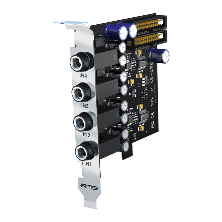
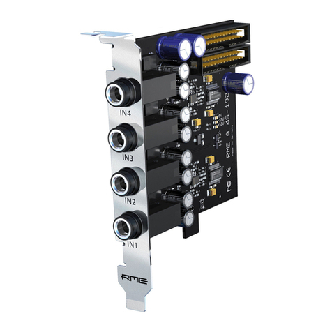
Thank you for choosing the AI4S-192. This Analog Expansion Board adds 4 analog inputs in
professional quality to RME's HDSP 9632. Level adjustment, balanced circuit design, 111 dBA
SNR and highest suppression of PC-noise guarantee perfect sound quality.
2. Package Contents
Please ensure that all the following parts are included in the AI4S-192's packaging box:
•Analog Expansion Board
•1 flat ribbon cable, 26 pins
•1 Set of nuts
•Manual, drill template
3. Hardware Requirements
The AI4S-192 can only be connected to the HDSP 9632. No more than one AI4S-192 can be
connected to each HDSP 9632.
4. Technical Specifications
•Resolution AD: 24 Bit
•Signal to Noise ratio (SNR): 109 dB RMS unweighted, 111 dBA @ 44.1 kHz
•THD @ -3 dBFS: -101 dB, < 0.001 %
•THD+N @ -3 dBFS: -99 dB, < 0.0015 %
•Crosstalk: 108 dB
•Frequency response AD @ 44.1 kHz, -0.5 dB: 5 Hz -21.5 kHz
•Frequency response AD @ 96 kHz, -0.5 dB: 5 Hz –45.3 kHz
•Frequency response AD @ 192 kHz, -1 dB: 5 Hz -74 kHz
•Input: 4 x 1/4" TRS jack, servo balanced
•Input impedance: 10 kOhm
•Input sensitivity: Lo Gain, +4 dBu, -10 dBV
•Input level for 0 dBFS @ Lo Gain: +19 dBu
•Input level for 0 dBFS @ +4 dBu: +13 dBu
•Input level for 0 dBFS @ -10 dBV: +2 dBV
•Power supply via flat ribbon cable
•Standard bracket, board dimensions 90 x 95 mm

User's Guide AI4S-192
4
5. Hardware Installation
Important: Switch off the computer and remove the power cable from the power supply be-
fore fitting the AI4S-192.
1. Disconnect the power cable and all other cables from the computer.
2. Remove the PC housing; further information on how to do this can be obtained from your
computer´s instruction manual.
3. Neutralize the static build up by touching the PC metal-chassis before unpacking the AI
from the protective bag.
4. Connect AI and HDSP 9632 using the supplied 26-pin flat cable.
5. Insert the AI into a free slot, press and fasten the screw. The AI needs no slot on the moth-
erboard, but includes a stabilizing edge, which fits in both PCI and ISA slots.
6. Re-insert the PCI-card in a PCI slot and fasten the screw.
7. Re-place the PC housing and tighten the screws.
8. Re-connect the power cable and all other cables/connections.
Connecting an AI4S-192 to a HDSP 9632
Both AI4S-192 and AO4S-192 have two flat cable connectors. The second connector allows to
use an AI4S-192 together with an AO4S-192.

User's Guide AI4S-192
5
6. Alternative Installation
Installation is done comfortably as described using the attached bracket. Alternatively it is pos-
sible to mount the AI at a different place inside the computer using the supplied nuts. This re-
quires to drill 4 holes into the housing.
RME does not accept claims for damages of any kind when installing the AI in this
way! Modifications to the housing should be done by qualified technicians only, and
only after having removed all components from the housing (danger of short circuit
by metal splinter etc).
1. Remove the bracket from the AI (2 screws).
2. Carefully check that the desired location offers a flat plane, is free from any voltage carrying
devices or cables, and that the AI does not get in contact with other devices even when the
housing is closed.
3. Please note that the lenght of the supplied cables does not allow any distance to the HDSP
9632 card.*
4. Drill 4 holes, diameter 0.5" (13 mm), distance of 0.75" (19.05 mm) each, at the desired
place (see drill template).
5. Fit the AI into the holes and fix it with the supplied nuts.
*The supplied 26-pin flat ribbon cable is a common component, available in any electronics
shop. A cable of up to 1 meter length can be used without a problem.
7. Operation and Usage
Switch on the computer and boot the OS. 4 additional inputs should now be available within
any audio software.
Note: the AI carries three SMD LEDs, indicating the presence of the power supplies +5V, +12V
and –12 V.
8. Analog Inputs
The analog inputs are accessible through stereo ¼" TRS jacks.
The AI4S-192 is fitted with electronically balanced, single channel inputs (+ = tip). The servo
balanced input circuit allows to use monaural TS jacks (unbalanced) with no loss in level.
When using unbalanced cables with stereo TRS jacks: be sure to connect the 'ring' contact
of the stereo TRS jack (pin 3 of a XLR jack) to ground. Otherwise noise may occur, caused
by the unconnected negative input of the balanced input.
One of the main issues when working with an AD-converter is to maintain the full dynamic
range within the best operating level. Therefore the HDSP 9632 and the AI/AO4S-192 use hi-
quality electronic switches, which allow for a perfect adaptation of all inputs to the three most
often used studio levels.
The 'standardized' studio levels do not result in a (often desired) full scale level, but take some
additional digital headroom into consideration. The amount of headroom is different in different
standards, and again differently implemented by different manufacturers. Because of this we
decided to define the levels of the HDSP 9632 in a most compatible way.

User's Guide AI4S-192
6
Reference 0 dBFS @ Headroom
Lo Gain +19 dBu 15 dB
+4 dBu +13 dBu 9 dB
-10 dBV +2 dBV 12 dB
With +4 dBu selected, the according headroom meets the latest EBU recommendations for
Broadcast usage. At -10 dBV 12 to 15 dB headroom are common practice, each mixing desk
operating at -10 dBV is able to send and receive much higher levels. Lo Gain allows to work
with high levels, best suited for professional users who prefer to work balanced and at highest
levels.
The above levels are also found in our ADI-8 series of AD/DA converters, the Multiface, and
even our Mic-Preamps QuadMic and OctaMic. Therefore all RME devices are fully compatible
to each other.
9. Warranty
Each individual AI4S-192 undergoes comprehensive quality control and a complete test in a
PC environment at RME before shipping. The usage of high grade components allows us to
offer a full two year warranty. We accept a copy of the sales receipt as valid warranty legitima-
tion.
RME’s replacement service within this period is handled by the retailer. If you suspect that your
card is faulty, please contact your local retailer. The warranty does not cover damage caused
by improper installation or maltreatment -replacement or repair in such cases can only be car-
ried out at the owner’s expense.
RME does not accept claims for damages of any kind, especially consequential damage. Liabil-
ity is limited to the value of the AI4S-192. The general terms of business drawn up by Synthax
Audio AG apply at all times.
10. Appendix
RME news, driver updates and further product information are available on our website:
http://www.rme-audio.de
If you prefer to read the information off-line, you can load a complete copy of the RME website
from the RME Driver CD (in the \rmeaudio.web directory) into your browser.
Trademarks
All trademarks and registered trademarks belong to their respective owners. RME and Ham-
merfall are registered trademarks of RME Intelligent Audio Solutions.
Copyright Matthias Carstens, 7/2003. Version 1.0
Current driver version: W2k: 2.60
Although the contents of this User’s Guide have been thoroughly checked for errors, RME can not guarantee that it is correct
throughout. RME does not accept responsibility for any misleading or incorrect information within this guide. Lending or
copying any part of the guide or the RME drivers CD, or any commercial exploitation of these media without express written
permission from RME Intelligent Audio Solutions is prohibited. RME reserves the right to change specifications at any time
without notice.

User's Guide AI4S-192
7
CE
This device has been tested and found to comply with the limits of the European Council Direc-
tive on the approximation of the laws of the member states relating to electromagnetic com-
patibility (EMVG) according to EN 55022 class B and EN50082-1.
FCC Compliance Statement
Certified to comply with the limits for a Class B computing device according to subpart J or part
15 of FCC rules. See instructions if interference to radio reception is suspected.
FCC Warning
This equipment has been tested and found to comply with the limits for a Class B digital de-
vice, pursuant to part 15 of the FCC rules. These limits are designed to provide reasonable
protection against harmful interference in a residential installation.
This device complies with part 15 of FCC rules. Operation is subject to the following two condi-
tions:
1. This device may not cause harmful interference
2. This device must accept any interference received, including interference that may cause
undesired operation.
However, there is no guarantee that interference will not occur in a particular installation. If this
equipment does cause harmful interference to radio or television reception, which can be de-
termined by turning the equipment off and on, the user is encouraged to try to correct the inter-
ference by one or more of the following measures:
•Reorient or relocate the receiving antenna
•Increase the seperation between the equipment and receiver
•Connect the equipment into an outlet on a circuit different from that to which the receiver is
connected
•Consult the dealer or an experienced radio/TV technician for help.
In order for an installation of this product to maintain compliance with the limits for a Class B
device, shielded cables must be used for the connection of any devices external to this prod-
uct.
Table of contents
Other RME Audio Computer Hardware manuals
