RME Audio HDSPe RayDAT User manual

User's Guide
HDSPe RayDAT
PCI Express Digital I/O Card
2 + 2 + 32 Channels AES / SPDIF / ADAT Interface
24 Bit / 192 kHz Digital Audio
72 x 36 Matrix Router
2 x MIDI I/O
TotalMix™
24 Bit / 192 kHz
SteadyClock FS™
SyncCheck™
2
User's Guide HDSPe RayDAT © RME
Safety Instructions and Proper use
Read the manual carefully and completely before using the device. Pay attention to
the following information on how to use and operate the HDSPe RayDAT safely. Im-
proper use can lead to loss of warranty claims (see warranty statement on page 82).
Proper Use
The HDSPe RayDAT is a digital interface card for professional audio applications for installation
in CE approved class B computers with PCI Express slot.
To comply with the European CE standard, the HDSPe RayDAT must be used
in a CE approved Class B computer. All connecting cables must be shielded.
The computer and all cables connected to the HDSPe RayDAT must be
properly grounded. Operation with non-certified computers and cables may
cause interference to other devices as well as the HDSPe RayDAT.
Safety Instructions
The HDSPe RayDAT has no user-serviceable parts. Repair work must only be carried out by
qualified personnel.
The HDSPe RayDAT must not come into contact with water or humidity. Extreme temperatures
must be avoided.
Changes or modifications of the HDSPe RayDAT not approved by RME may void the warranty
and guarantee.
Unauthorized servicing/repair voids warranty. Only use accessories
specified by the manufacturer.

User's Guide HDSPe RayDAT © RME
3
General
1 Introduction ...............................................................8
2 Package Contents.....................................................8
3 System Requirements ..............................................8
4 Brief Description and Characteristics.....................8
5 Hardware Installation................................................9
6 Hardware –Connectors
6.1 External Connectors ..............................................9
6.2 Internal Connectors..............................................10
Driver Installation and Operation - Windows
7 Driver and Firmware
7.1 Driver Installation .................................................12
7.2 Deinstalling the Drivers........................................12
7.3 Firmware Update .................................................12
8 Configuring the HDSPe RayDAT
8.1 Settings Dialog.....................................................13
8.2 Settings Dialog –Pitch.........................................15
8.3 Option WDM Devices ..........................................16
8.4 Tab Global ...........................................................17
8.5 Clock Modes –Synchronization...........................18
9 Operation and Usage
9.1 Playback...............................................................19
9.2 DVD Playback (AC-3 / DTS)................................19
9.3 Multi-client Operation...........................................20
9.4 Digital Recording..................................................21
10 Operation under ASIO 2.0
10.1 General ................................................................22
10.2 Channel Count under ASIO .................................22
10.3 Known Problems..................................................23
11 Using more than one HDSPe RayDAT ..................23
12 DIGICheck................................................................24
Driver Installation and Operation - Mac OS X
13 Driver and Flash Update
13.1 Driver Installation .................................................26
13.2 De-installing the Drivers.......................................26
13.3 Firmware Update .................................................26
14 Configuring the HDSPe RayDAT
14.1 Settings Dialog.....................................................27
14.2 Clock Modes –Synchronization...........................29
15 Mac OS X FAQ
15.1 MIDI doesn't work ................................................30
15.2 Repairing Disk Permissions.................................30
15.3 Supported Sample Rates.....................................30
15.4 Channel Count under Core Audio........................30
15.5 Various Information..............................................31
16 Using more than one HDSPe RayDAT ..................31
17 DIGICheck................................................................32

4
User's Guide HDSPe RayDAT © RME
Connections
18 Connections
18.1 ADAT....................................................................34
18.2 AES/EBU..............................................................34
18.3 SPDIF (Coaxial, Optical)......................................35
18.4 MIDI......................................................................36
19 Word Clock
19.1 Word Clock Input and Output...............................36
19.2 Technical Description and Background................37
19.3 Cables and Termination.......................................37
19.4 General Operation................................................38
TotalMix FX
20 Routing and Monitoring
20.1 Overview ..............................................................40
20.2 The User Interface ...............................................42
20.3 The Channels.......................................................43
20.4 Section Control Room..........................................46
20.5 The Control Strip..................................................47
20.5.1 View Options ................................................48
20.5.2 Snapshots - Groups .....................................49
20.5.3 Channel Layout –Layout Presets.................50
20.5.4 Scroll Location Markers................................51
20.6 Preferences..........................................................52
20.6.1 Store for Current User or all Users...............53
20.7 Settings
20.7.1 Mixer Page ...................................................54
20.7.2 MIDI Page.....................................................55
20.7.3 OSC Page ....................................................56
20.7.4 Aux Devices..................................................57
20.8 Hotkeys and Usage..............................................58
20.9 Menu Options.......................................................59
20.10 Menu Window ......................................................60
21 The Matrix
21.1 Overview ..............................................................60
21.2 Elements of the Matrix view.................................60
21.3 Operation..............................................................61
22 Tips and Tricks
22.1 ASIO Direct Monitoring (Windows) ......................61
22.2 Copy a Submix.....................................................61
22.3 Doubling the Output Signal (Mirror)......................61
22.4 Delete a Submix...................................................62
22.5 Copy and Paste everywhere ................................62
22.6 Recording a Submix - Loopback..........................62
22.7 MS Processing.....................................................63
23 MIDI Remote Control
23.1 Overview ..............................................................64
23.2 Mapping................................................................64
23.3 Setup....................................................................65
23.4 Operation..............................................................65
23.5 MIDI Control.........................................................66
23.6 Loopback Detection .............................................67
23.7 OSC (Open Sound Control).................................67
24 DAW Mode................................................................68
25 TotalMix Remote......................................................69

User's Guide HDSPe RayDAT © RME
5
Technical Reference
26 Technical Specifications
26.1 Inputs ...................................................................72
26.2 Outputs ................................................................72
26.3 Digital...................................................................73
26.4 MIDI......................................................................73
27 Technical Background
27.1 AES/EBU - SPDIF................................................74
27.2 Lock and SyncCheck ...........................................75
27.3 Latency and Monitoring........................................76
27.4 DS –Double Speed .............................................77
27.5 QS –Quad Speed................................................78
27.6 SteadyClock.........................................................78
27.7 Terminology.........................................................79
Miscellaneous
28 Accessories .............................................................82
29 Warranty...................................................................82
30 Appendix..................................................................83
31 Declaration of Conformity......................................84

6
User's Guide HDSPe RayDAT © RME

User's Guide HDSPe RayDAT © RME
7
User's Guide
HDSPe RayDAT
General

8
User's Guide HDSPe RayDAT © RME
1. Introduction
Thank you for choosing the RME HDSPe RayDAT. This unique audio card is capable of trans-
ferring digital audio data from practically any source directly to Windows and Mac computers.
The latest Plug and Play technology guarantees a simple installation, even for the inexperienced
user. Numerous unique features like a well thought-out Settings dialog and an integrated routing
solution realize a quick, comfortable and efficient operation of the HDSPe RayDAT.
The package contains drivers for Windows (XP, Vista, 7, 8, 10) and Mac OS X x86 (Intel).
RME’s high-performance philosophy guarantees maximum system performance by executing as
many functions as possible not in the driver (i.e. the CPU), but directly within the audio hard-
ware.
2. Package Contents
Please check your HDSPe RayDAT’s package contains each of the following:
HDSPe RayDAT PCI Express card
HDSPe RayDAT expansion board
Quick Info guide
Digital breakout cable (XLR / RCA)
MIDI breakout cable
Expansion Board ribbon cable (14-conductor)
2 optical cable (TOSLINK), 2 m (6.6 ft)
3. System Requirements
Windows XP or higher, Mac OS X Intel (10.6 or higher)
PCI Express Interface: one free PCI Express slot, 1 Lane, version 1.1
4. Brief Description and Characteristics
All settings can be changed in real-time
Buffer sizes/latencies from 32 up to 8192 samples selectable
32 channels 192 kHz/24 bit record/playback via ADAT optical
16 channels 96 kHz/24 bit record/playback via ADAT optical (S/MUX)
8 channels 192 kHz/24 bit record/playback via ADAT optical (S/MUX4)
Automatic and intelligent master/slave clock control
Unsurpassed Bitclock PLL (audio synchronization) in ADAT mode
TotalMix for latency-free submixes and perfect ASIO Direct Monitoring
SyncAlign guarantees sample aligned and never swapping channels
SyncCheck tests and reports the synchronization status of input signals
2 x MIDI I/O, 32 channels high-speed MIDI
DIGICheck DSP: Level meter in hardware, peak- and RMS calculation
TotalMix: 2592 channel mixer with 42 bit internal resolution
SteadyClock FS: Jitter-immune, super-stable digital clock
Optional Time Code module (TCO) for external Video-/SMPTE synchronization

User's Guide HDSPe RayDAT © RME
9
!
5. Hardware Installation
To simplify installation it is recommended to first install the drivers before the unit is connected to
the computer. But it will also work the other way round.
Before installing the PCI Express card, please make sure the computer is switched off and
the power cable is disconnected from mains supply. Inserting or removing the card while the
computer is in operation can cause irreparable damage to both motherboard and card!
1. Disconnect the power cord and all other cables from the computer.
2. Remove the computer's housing. Further information on how to do this can be obtained from
your computer’s instruction manual.
3. Important: Before removing the HDSPe RayDAT from its protective bag, discharge any stat-
ic in your body by touching the metal chassis of the PC.
4. Prior to installation: Connect the HDSPe RayDAT card to the Expansion Board using the
supplied flat ribbon cable.
5. Insert the HDSPe RayDAT firmly into a free PCI Express slot, press and fasten the screw.
6. Insert the Expansion Board and fasten the screw.
7. Replace the computer's housing.
8. Reconnect all cables including the power cord.
6. Hardware - Connectors
6.1 External Connectors
HDSPe RayDAT consists of the main PCIe board and an Expansion Board. All the essential
electronics are located on the PCI card, so it will also work without the Expansion Board.
The main board's bracket has
two ADAT optical inputs and
outputs, as well as a 9-pin D-
sub socket. AES/EBU and
coaxial SPDIF input and out-
put are provided via the includ-
ed breakout cable, whereby the
red RCA socket is the output.
The Expansion Board's bracket
gives access to a third and
fourth ADAT optical input and
output.
ADAT4 can also be used as
optical SPDIF I/O, if set up
accordingly in the Settings
dialog.
The included MIDI breakout cable is connected to the 9-pin Mini-DIN connector, providing two
MIDI inputs and outputs.
Note: If neither MIDI I/O nor a third and fourth ADAT I/O are required, it is not necessary to in-
stall the Expansion Board at all.
Optional TCO
The optional Time Code Option is connected to the main board with a 10-pin flat ribbon cable.
Further details can be found in the TCO manual.

10
User's Guide HDSPe RayDAT © RME
6.2 Internal Connectors
X300
14-pin connector for the included HDSPe RayDAT Expansion Board.
X402
10-pin connector for a connection of the Time Code Option (TCO).
X100
No function. Used to program the card in the factory.
X400 Sync In
Internal word clock input for synchronization of multiple cards via SYNC OUT.
X401 Sync Out
This 3-pin connector carries an internal word clock signal. It can be used to synchronize multiple
cards with sample accuracy, and without the need for an external connection. The card where
SYNC OUT is used is Master, the one with SYNC IN is Slave. In the Settings dialog the Slave
has to be set to Sync In under Pref. Sync Ref, the Clock Mode must be set to AutoSync.
SPDIF OUT (X502)
Internal SPDIF output, operates in parallel to the coaxial output.
AEB1 IN / CD IN (X503)
This internal digital input can be used with both SPDIF and ADAT format.
SPDIF
Connection to an internal CD-ROM drive with digital audio output. Allows for a direct trans-
fer of digital audio data within the computer.
Connection to SPDIF output of another card. This internal SPDIF connection can be used
to synchronize multiple cards with sample accuracy, and without the need for an external
connection. Please note that the external SPDIF input can no longer be used.
ADAT
Connection of a TEB* (TDIF Expansion Board). The highest sample rate is 96 kHz, the 4-
channel Double Wire mode (S/MUX) is automatically activated in Double Speed mode. Se-
lect AEB / TEB ADAT1 In in the Settings dialog.
Connection of an AEB4-I* or AEB8-I*. When using these Expansion Boards X507 (single 3-
pin socket) must also be connected to the Expansion Board. The highest sample rate is 48
kHz. Select AEB /TEB ADAT1 In in the Settings dialog.
AEB2 IN (X505)
Connection of a second AEBx-I* or TEB*. GND is the pin near the edge of the PCB. Select AEB
/ TEB ADAT2 In in the Settings dialog. In this configuration the optical input ADAT2 can not be
used anymore.
ADAT 1 OUT (X504)
This internal ADAT output carries the same audio data as the optical output ADAT1. Connecting
an AEB4-O* or AEB8-O*, the highest sample rate is 48 kHz. Connecting a TEB* the highest
sample rate is 96 kHz, the 4-channel Double Wire mode (S/MUX) is automatically activated.
GND is the pin near the edge of the PCB.
ADAT 2 OUT (X501)
This internal ADAT output carries the same audio data as the optical output ADAT2. See ADAT1
OUT for details. Both ports can be used to operate one AEBx-O* each, for a maximum of 16
analog outputs.
* No longer available.

User's Guide HDSPe RayDAT © RME
11
User's Guide
HDSPe RayDAT
Driver Installation and Operation - Windows

12
User's Guide HDSPe RayDAT © RME
7. Driver and Firmware
7.1 Driver Installation
After the HDSPe RayDAT card has been installed correctly (see 5. Hardware Installation), and
the computer has been switched on, Windows will recognize the new hardware component and
start its ‘Hardware Wizard’. In case the drivers had not been installed before exit the assistant.
RME is constantly improving the drivers. Please download the latest drivers from the RME web-
site. Driver version 4.30 or higher is available via http://rme.to/downloads. Unzip the down-
loaded file and start the driver installation with rmeinstaller.exe. Windows now installs the drivers
of the HDSPe system and registers the card as audio device. After a reboot the card is ready to
be used.
After the reboot, the icons of TotalMix FX and Settings dialog appear
in the notification area. Windows might hide them behind the trian-
gle, click on it to access them and to configure their appearance.
Driver Updates do not require to remove the existing drivers. Simply install the new driver over
the existing one.
7.2 Deinstalling the Drivers
A deinstallation of the driver files is not necessary –and not supported by Windows anyway.
Thanks to full Plug & Play support, the driver files will not be loaded after the hardware has been
removed. If desired these files can then be deleted manually.
Unfortunately Windows Plug & Play methods do not cover the additional autorun entries of To-
talMix, the Settings dialog, and the registration of the ASIO driver. Those entries can be re-
moved from the registry through a software deinstallation request. This request can be found
(like all deinstallation entries) in Control Panel, Software. Click on the entry 'RME Hammerfall
DSP (WDM)'.
7.3 Firmware Update
The Flash Update Tool updates the HDSPe RayDAT to the latest firmware version. It requires
an already installed driver.
Start the program pcie_fut.exe. The Flash Update Tool displays the current revision of the
HDSPe RayDAT, and whether it needs an update or not. If so, then please press the 'Update'
button. A progress bar will indicate when the flash process is finished. The bar moves slowly first
(program), then faster (verify).
If more than one interface card is installed, all cards can be flashed by changing to the next tab
and repeating the process.
After the update the PCI Express card needs to be reset. This is done by powering down and
shutting off the PC. A warm boot is not enough!
When the update fails (status: failure), the card's second BIOS will be used from the next cold
boot on (Secure BIOS Technology). Therefore the card stays fully functional. The flash process
should then be tried again on a different computer.
User's Guide HDSPe RayDAT © RME
13
8. Configuring the HDSPe RayDAT
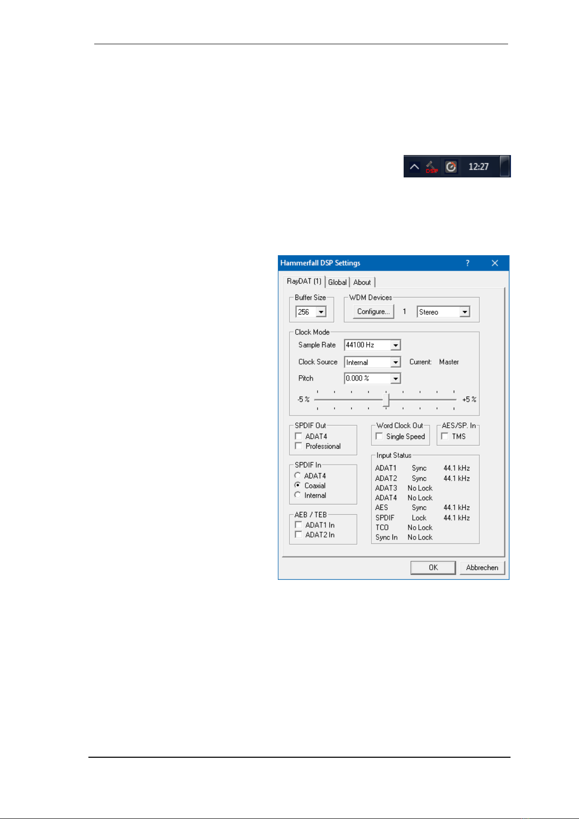
8.1 Settings Dialog
Configuration of the HDSPe RayDAT is done via its own settings dialog. The panel 'Settings' can
be opened:
by clicking on the hammer symbol in the Task Bar's notification area
The mixer of the HDSPe RayDAT (TotalMix) can be opened:
by clicking on the mixer icon in the Task Bar's notification area
The hardware of the HDSPe system offers a number of helpful, well thought-of practical func-
tions and options which affect how the card operates - it can be configured to suit many different
requirements. The following is available in the 'Settings' dialog:
Configuration of digital I/Os
Synchronization behaviour
State of input and output
Current sample rate
Latency
Any changes made in the Settings dia-
log are applied immediately - confirma-
tion (e.g. by clicking on OK or exiting
the dialog) is not required.
However, settings should not be
changed during playback or record if it
can be avoided, as this can cause un-
wanted noises.
Also, please note that even in 'Stop'
mode, several programs keep the re-
cording and playback devices open,
which means that any new settings
might not be applied immediately.
The status displays at the bottom of the
dialog box give the user precise infor-
mation about the current status of the
system, and the status of all digital sig-
nals.
The tab About includes information
about the current driver version.
Buffer Size
The setting Buffer Size determines the latency between incoming and outgoing ASIO and WDM
data, as well as affecting system stability (see chapter 10).

14
User's Guide HDSPe RayDAT © RME
WDM Devices
Allows to freely set which I/Os are available as WDM devices, if these are stereo or multi-
channel devices (up to 8 channels), and if one or multiple of the currently active WDM devices
should have the Speaker property. More details are found in chapter 8.3.
Clock Mode
Sample Rate
Sets the currently used sample rate. Offers a central and comfortable way of configuring the
sample rate of all WDM devices to the same value, as since Vista the audio software is no long-
er allowed to set the sample rate. However, an ASIO program can still set the sample rate by
itself.
During record/playback the selection is greyed out, so no change is possible.
Clock Source
The unit can be configured to use its own clock (Internal = Master), or one of the input signals
(Word/TCO, AES, SPDIF, ADAT 1-4, Sync In). If the selected source isn't available (No Lock),
the unit will change to the next available one (RME’s AutoSync behaviour). If none is available
then the internal clock is used. The current clock source is displayed as Current.
Pitch
More information on Pitch is available in chapter 8.2.
SPDIF Out
The SPDIF output signal is constantly available at the phono plug. After selecting ADAT4 it is
also routed to the optical TOSLINK output ADAT4. For further details about the setting Profes-
sional please refer to chapter 22.2.
SPDIF In
Defines the input for the SPDIF signal. Coaxial relates to the RCA socket, Optical to the optical
TOSLINK input ADAT4, Internal to the jumper AEB1 In / CD In.
AEB / TEB
ADAT1 In switches the input ADAT1 from the optical connector to the internal connector AEB 1
In / CD In.
ADAT2 In switches the input ADAT2 from the optical connector to the internal connector AEB2
In.
Word Clock Out
The word clock output signal usually equals the current sample rate. Selecting Single Speed
causes the output signal to always stay within the range of 32 kHz to 48 kHz. So at 96 kHz and
192 kHz sample rate, the output word clock is 48 kHz.
AES/SP.In
TMS activates the transmission of Channel Status data and Track Marker information from the
AES/EBU input signal.
Input Status
SyncCheck indicates whether there is a valid signal (Lock, No Lock) for each input (ADAT 1-4,
SPDIF, AES, Word/TCO and internal Sync), or if there is a valid and synchronous signal (Sync).
Each input has its own frequency measurement and display of the input signal's current sample
rate.

User's Guide HDSPe RayDAT © RME
15
!
!
8.2 Settings dialog - Pitch
Usually soundcards and audio interfaces generate their internal clock (master mode) by a
quartz. Therefore the internal clock can be set to 44.1 kHz or 48 kHz, but not to a value in be-
tween. SteadyClock, RME's sensational Low Jitter Clock System, is based on a Direct Digital
Synthesizer (DDS). This superior circuitry can generate nearly any frequency with highest preci-
sion.
DDS has been implemented into the HDSPe RayDAT with regard to the needs of professional
video applications, as well as to achieve maximum flexibility. The section Pitch includes both a
list of typical video frequencies (so called pull up/pull down at 0.1% and 4%) and a fader to freely
change the basic sample rate in steps of 1 Hz (!) over a range of +/- 5%.
The DDS dialog requires the HDSPe RayDAT to be in clock mode Master! The frequency
setting will only be applied to this one specific card!
Changing the sample rate in bigger steps during record/playback often results in a loss of
audio, or brings up warning messages of the audio software. Therefore the desired sample
rate should be set at least coarsely before starting the software.
Coarse
Coarse modification in steps of 50 Hz
is done by clicking with the mouse to
the left and right of the fader knob.
Fine
Fine modification in steps of 1 Hz is
done by using the left/right cursor
keys.
Reset
Ctrl key plus left mouse click.
Application examples
Pitch allows for a simultaneous change of speed and tune during record and playback. From
alignment to other sources up to creative effects –everything is possible.
Pitch enables you to intentionally de-tune the complete DAW. This way, the DAW can match
instruments which have a wrong or unchangeable tuning.
Pitch allows for the change of the sample rate of all WDM devices at the same time. Since Vista
this is no longer possible via the audio program, thus requires a manual reconfiguration of all
WDM devices. Changing the sample rate from the Settings dialog solves this problem.
16
User's Guide HDSPe RayDAT © RME
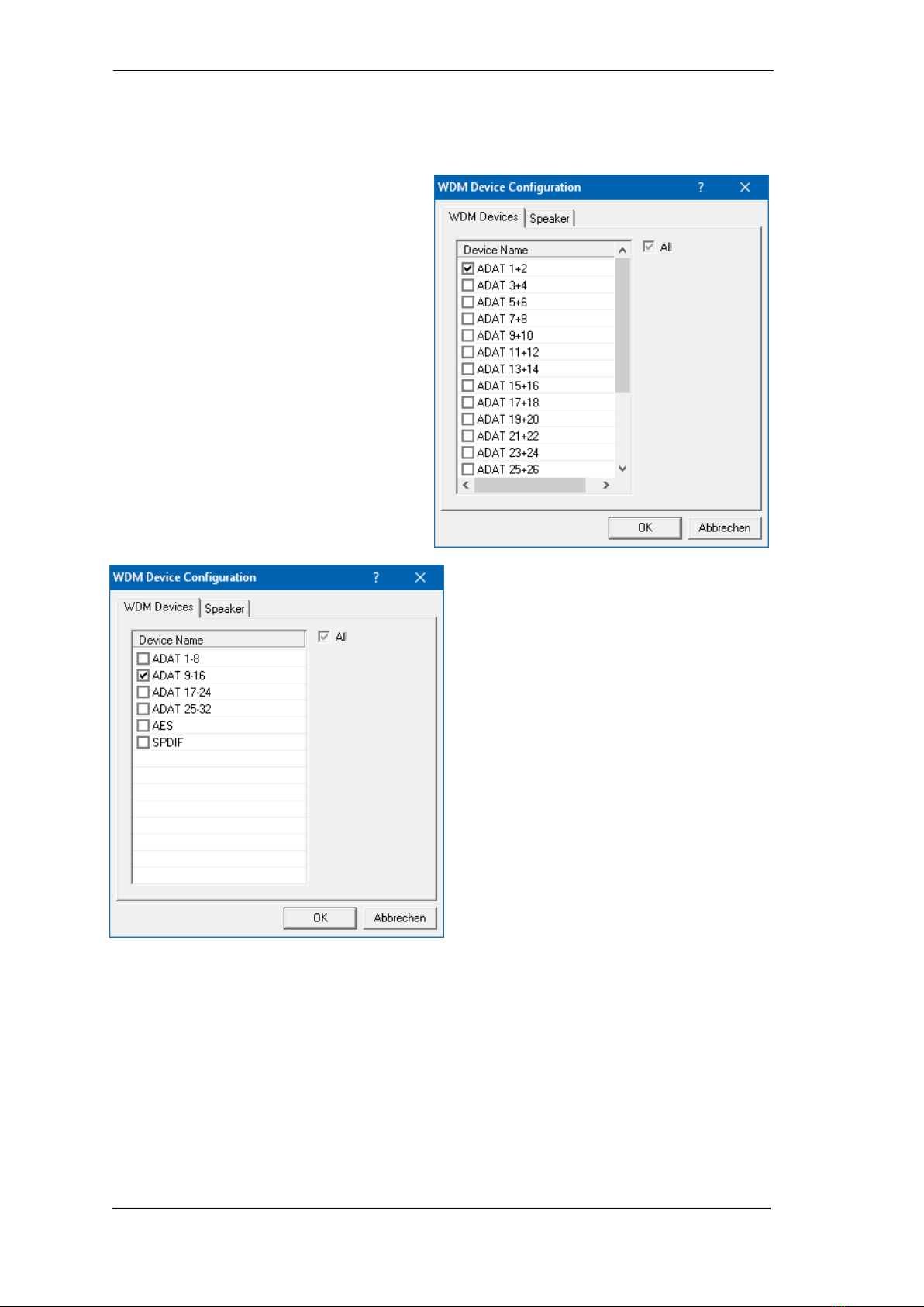
8.3 Option WDM Devices
The area WDM Devices gives configuration access, a status display showing the number of
currently enabled WDM devices, and a listbox to select between Stereo or Multi-Channel devic-
es.
The number represents both record and
playback devices, so ‘1’ means one input
and one output device.
The screenshot to the right shows the stereo
WDM devices available with the HDSPe
RayDAT, and that only ADAT 1/2 has been
activated. Any number can be activated. Also
only higher numbered devices might be ac-
tive. For example using the output ADAT 5/6
for system based audio does not require to
activate any other stereo device. Only ADAT
5/6 will show up in the Windows Sound con-
trol panel.
The checkbox All to the right allows for a
quick check/uncheck of all devices.
The screenshot to the left shows the multi-
channel WDM devices available with the
HDSPe RayDAT after selecting ‘Multi-
Channel’ in the WDM Devices listbox and
hitting WDM Configure. In this example the
device ADAT 9 to 16 is active.
Using a multi-channel WDM device allows for
the use of multi-channel playback with spe-
cialized software as well as Surround sound
from DVD or Blu-Ray player software.
Changing to the tab Speaker presents a list
of all currently activated WDM devices. Any
of these can now get the Speaker property.
Please note that defining more than one device as Speaker usually makes no sense, and the
speakers also don’t get numbered or renamed in Windows, so it is impossible to find out which
one is which.
Multichannel devices can be addressed as 2-channel, 4-channel, 6-channel or 8-channel device.
After leaving the dialog with OK the WDM devices are reloaded so Windows sees their new
properties.
User's Guide HDSPe RayDAT © RME
17
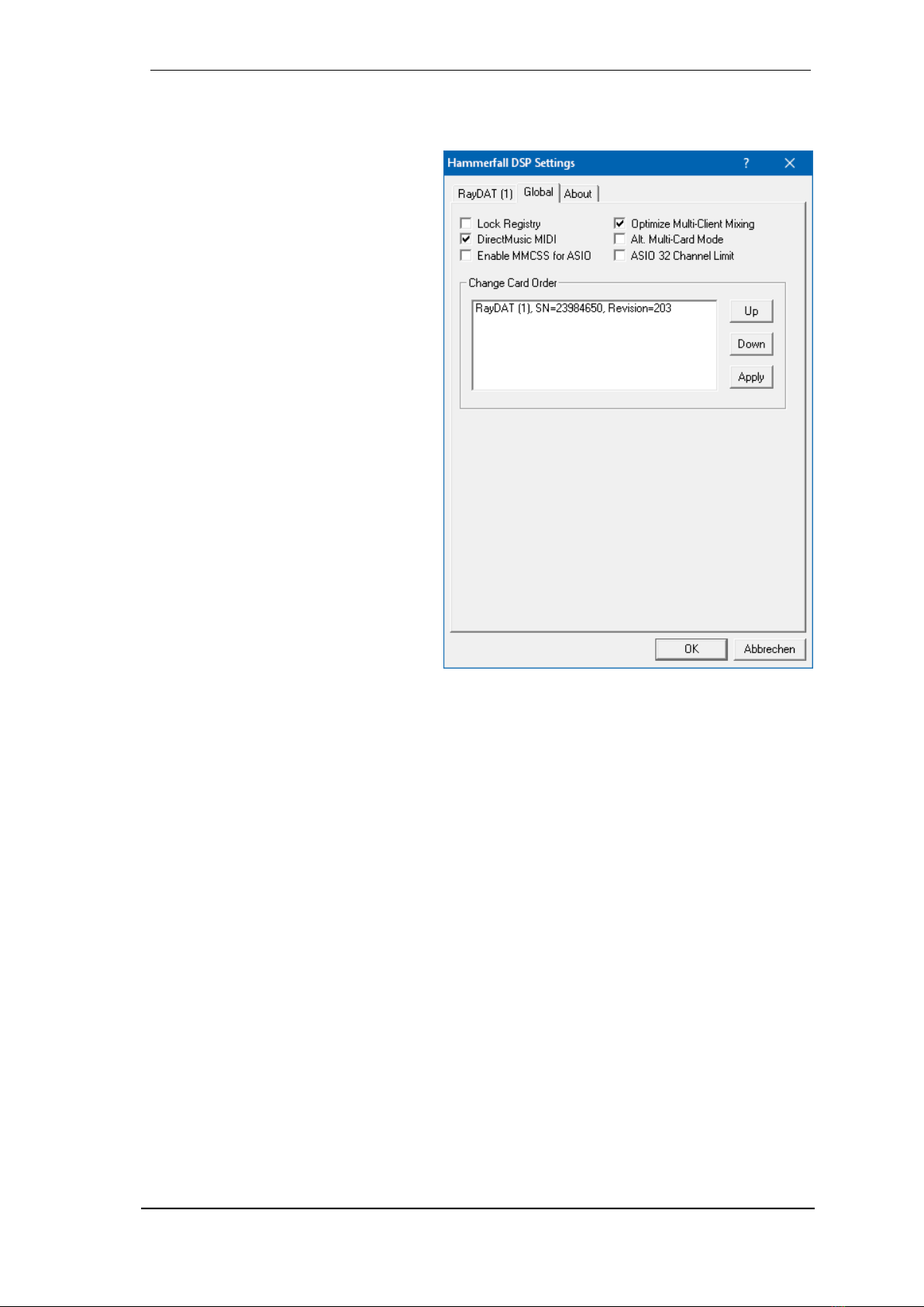
8.4 Tab Global
This tab includes several options that work on all currently installed cards.
Lock Registry
Default: off. Checking this option brings
up a dialog to enter a password.
Changes in the Settings dialog are no
longer written to the registry. As the
settings are always loaded from the
registry when starting the computer, this
method provides an easy way to define
an initial state of the HDSPe RayDAT.
Optimize Multi-Client Mixing
Default: off. Checking this option re-
moves short noise bursts when multi-
client playback starts, but will also intro-
duce some additional CPU load.
DirectMusic MIDI
Disables DirectMusic MIDI. Windows
MIDI remains active.
Alt. Multi-Card Mode
Activates an alternative multi-card mode
in which when one card is started, the
other card is always started as well.
This prevents audio problems in mixed
ASIO/WDM mode, such as no ASIO
sound on the first card when WDM is
started on the second.
Enable MMCSS for ASIO activates support with higher priority for the ASIO driver. Note: At this
time, activating this option seems to be useful only with the latest Cubase/Nuendo at higher
load. With other software this option can decrease performance. The change becomes active
after an ASIO reset. Therefore it is easy to quickly check which setting works better.
ASIO 32 Channel Limit
Default: off. Checking this option limits the number of ASIO I/Os to 32. Reducing the number of
ASIO channels can be helpful in certain situations.
Change Card Order
This dialog lists all cards currently installed in the system and controlled by the driver. Their or-
der can then be changed by selecting a card and using the up/down arrows. Confirm the opera-
tion with the Apply button. This feature comes in handy if different cards are installed and a spe-
cific one of them should always be the first in the ASIO channel list.
At the end of the card info line the current firmware version is shown (Revision).
18
User's Guide HDSPe RayDAT © RME
!
8.5 Clock Modes - Synchronisation
In the digital world, all devices must be either Master (clock source) or Slave (clock receiver).
Whenever several devices are linked within a system, there must always be a single master
clock.
A digital system can only have one master! If the card’s clock mode is set to 'Internal', all
other devices must be set to ‘Slave’.
The HDSPe RayDAT’s utilizes a very user-friendly, intelligent clock control, called AutoSync. In
AutoSync mode, the system constantly scans the digital input for a valid signal. If any valid signal
is found, the card switches from the internal clock (Clock Source –Current Internal) to a clock
extracted from the input signal (Clock Source –Current AES, SPDIF, ADAT, TCO or Sync In).
The difference to a usual slave mode is that whenever the clock reference fails, the system will
automatically use its internal clock and operate in clock mode Master.
AutoSync guarantees that normal record and record-while-play will always work correctly. In
certain cases however AutoSync may cause feedback in the digital carrier, so synchronization
breaks down. To remedy this, switch the HDSPe’s clock mode over to 'Internal'.
RME’s exclusive SyncCheck technology enables an easy to use check and display of the cur-
rent clock status. The status box labelled Input Status indicates whether no signal (‘No Lock’), a
valid signal (‘Lock’) or a valid and synchronous signal (‘Sync’) is present at each of the digital
clock source inputs. In the field Clock Mode the clock reference is shown. See chapter 27.2.
Via Clock Source a preferred input can be defined. As long as the card sees a valid signal there,
this input will be designated as the sync source, otherwise the other inputs will be scanned in
turn. If none of the inputs are receiving a valid signal, the HDSPe automatically switches into
clock mode Master.
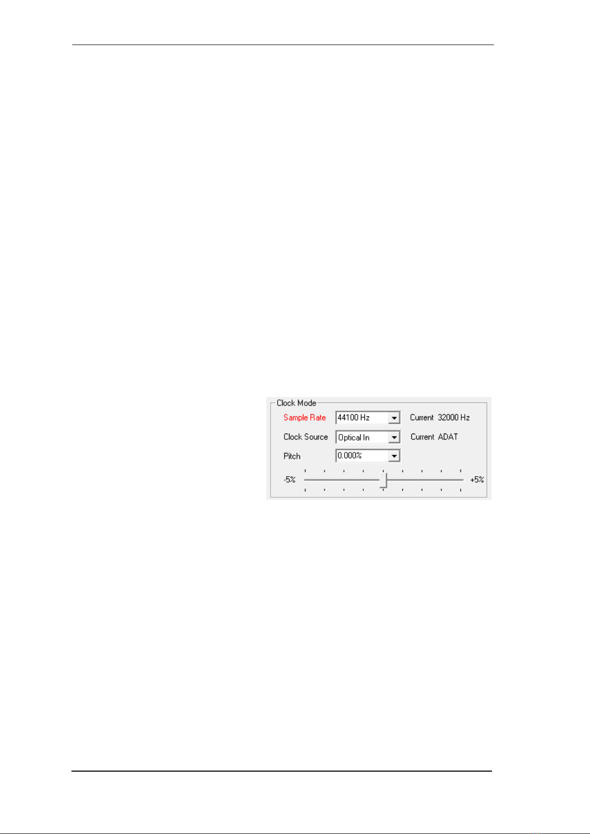
Under WDM the unit will (has to) set the
sample rate. Therefore the error shown to
the right can occur. A stable signal with a
sample rate of 32 kHz is detected at the
Word Clock input (Sync), but Windows
audio had been set to 44100 Hz before.
The red colour of the text label signals the
error condition, and prompts the user to
set 32000 Hz manually as sample rate.
Under ASIO the audio software sets the sample rate, so that such an error will usually not hap-
pen –but it can too. In slave mode the external sample rate has priority. Feeding 44.1 kHz will
prevent the ASIO software to set 48 kHz –obviously, as the only way to do so would be to enter
a different clock mode (Master/Internal).
In practice, SyncCheck provides the user with an easy way of checking whether all digital devic-
es connected to the system are properly configured. With SyncCheck, finally anyone can master
this common source of error, previously one of the most complex issues in the digital studio
world.

User's Guide HDSPe RayDAT © RME
19
!
!
9. Operation and Usage
9.1 Playback
In the audio application being used, HDSPe RayDAT must be selected as output device. This
can often be found in the Options, Preferences or Settings menus under Playback Device, Audio
Devices, Audio etc.
WDM playback devices are not available if the number of WDM devices is set to 0 in the
Settings dialog.
Although the HDSPe RayDAT comes with extensive support for system audio, setting it to be the
Default Device for playback could cause problems, especially when working with ASIO. RME
also recommends switching off all system sounds (via Control Panel Sound, tab Sounds).
Increasing the number and/or size of audio buffers in the application (WDM) or the RME Set-
tings dialog (ASIO) may prevent the audio signal from breaking up, but also increases latency
i.e. output is delayed.
Note: Since Vista the audio application can no longer control the sample rate under WDM.
Therefore the driver of the HDSPe RayDAT includes a way to set the sample rate globally for all
WDM devices, found within the Settings dialog. See chapter 8.1.
9.2 DVD-Playback (AC-3/DTS) under MME
Popular DVD software players can send their audio data stream to any AC-3/DTS capable re-
ceiver via the HDSPe's MADI channels.
The sample rate must be set to 48 kHz in the HDSPe RayDAT Settings dialog, or the soft-
ware will only playback a stereo 2-channel downmix via SPDIF.
In some cases the HDSPe RayDAT output device has to be selected in >Control Panel / Sound /
Playback< and be set as Default, or the software will not recognize it.
The DVD software's audio properties now show the options 'SPDIF Out' or similar. When select-
ing these, the software will transfer the non-decoded digital multichannel data stream to the
HDSPe.
Note: This 'SPDIF' signal sounds like chopped noise at highest level. The first 2 channels (Loud-
speaker) do not support digital AC-3/DTS playback.
Multichannel
DVD software player can also operate as software decoder, sending a DVD's multichannel data
stream directly as ‘analog’ signal to the HDSPe RayDAT. For this to work select the WDM play-
back device ’Loudspeaker’ of the MADI in Control Panel, Sound, tab Playback as Default.
In the audio properties of the DVD software now several multichannel modes are listed. If one of
these is selected, the software sends the decoded ‘analog’multichannel data to the HDSPe
RayDAT. TotalMix can then be used to play back via any desired output channels.
The typical channel assignment for surround playback is:
1 –Left 2 –Right 3 –Center 4 - LFE (Low Frequency Effects)
5 - SL (Surround Left) 6 - SR (Surround Right)

20
User's Guide HDSPe RayDAT © RME
Note 1: Selecting the MADI to be used as system playback device is against our recommenda-
tion, as professional interfaces should not be disturbed by system events. Make sure to re-
assign the selection after usage or to disable any system sounds (tab Sounds, scheme 'No au-
dio').
Note 2: The DVD player will be synced backwards from the MADI. This means when using Au-
toSync and/or word clock, the playback speed and pitch follows the incoming clock signal.
9.3 Multi-client Operation
RME audio interfaces support multi-client operation. Several programs can be used at the same
time. The formats ASIO and WDM can even be used on the same playback channels simulta-
neously. As WDM uses a real-time sample rate conversion (ASIO does not), all active ASIO
software has to use the same sample rate.
However, a better overview is maintained by using the channels exclusively. This is no limitation
at all, because TotalMix allows for any output routing, and therefore a playback of multiple soft-
ware on the same hardware outputs.
Inputs can be used from an unlimited number of WDM and ASIO software at the same time, as
the driver simply sends the data to all applications simultaneously.
RME's sophisticated tool DIGICheck operates like an ASIO host, using a special technique to
access playback channels directly. Therefore DIGICheck is able to analyse and display playback
data from any software, no matter which format it uses.
Table of contents
Other RME Audio Sound Card manuals

RME Audio
RME Audio DIGI96 User manual

RME Audio
RME Audio Hammerfall HDSP 9632 User manual

RME Audio
RME Audio DIGI 96/8 PST User manual

RME Audio
RME Audio DIGI96/8 PAD User manual

RME Audio
RME Audio TCO HDSP/FF User manual

RME Audio
RME Audio TEB User manual

RME Audio
RME Audio DIGI96 User manual

RME Audio
RME Audio DIGI96/8 PAD User manual

RME Audio
RME Audio DIGI32/8 User manual


