RME Audio TEB User manual

User's Guide
TEB
TDIF Expansion Board
for DIGI96/8 Series, Hammerfall Series
HDSP 9632 and HDSP 9652

User's Guide TEB
2
Contents
1Introduction.............................................................. 3
2Package Contents.................................................... 3
3Hardware Requirements........................................... 3
4Technical Specifications........................................... 4
5Hardware Installation................................................ 4
6Operation and Usage ............................................... 6
7Word Clock.............................................................. 7
8Double Speed .......................................................... 8
9Connector Pinout D-sub ........................................... 8
10 Warranty.................................................................. 9
11 Appendix.................................................................. 9

User's Guide TEB
3
1. Introduction
Thank you for choosing the RME EXB technology. The TDIF Expansion Boards adds an 8-
channel TDIF interface to all ADAT-capable RME cards. Special features include manual
choice of clock reference, status LEDs and a word clock output.
2. Package Contents
Please ensure that all the following parts are included in the TEB's packaging box:
•TDIF Expansion Board
•2 Data cable 2-core
•1 Cable adapter 5 ¼" to 2 x 3,5"
•Manual (PDF on RME Driver-CD)
3. Hardware Requirements
TEBs can only be used with RME cards.
DIGI96 Series
TEBs use the internal ADAT interface of the DIGI cards. Therefore they do not work with the
DIGI96 (which did not support ADAT).
One TEB can be connected and operated.
Hammerfall Series
An operation with the Hammerfall or Hammerfall Light requires board revision 1.5 or higher,
because the internal connector ADAT1Out was not implemented in earlier versions.
One TEB can be connected and operated. Additionally one AEBx-O can be used simultane-
ously.
HDSP 9632
One TEB can be connected and operated.
HDSP 9652
Two TEBs can be connected and operated simultaneously. One TEB can be used together with
either one AEBx-I or AEBx-O.
Hammerfall DSP Multiface / Digiface
Multiface and Digiface use the Hammerfall DSP PCI card. This card has no internal inputs or
outputs. Therefore no Expansion Boards can be used.

User's Guide TEB
4
4. Technical Specifications
•TDIF Port: D-sub 25-pin
•Double Line mode: 4 channels at 88.2 kHz and 96 kHz (not with DIGI96 series)
•Supported sample rates: 44.1 kHz, 48 kHz, varispeed (33 -57 kHz)
•Resolution: 24 bit
•Word clock out: BNC, low-impedance driver stage, 4 Vss into 75 Ohms, short-circuit-proof
•Sync source: ADAT (PCI card) or TDIF
•Power supply uses 3.5" floppy connector, 5 V DC, 100 mA
•Standard bracket, board dimensions: 75 x 95 mm
5. Hardware Installation
Important: Switch off the computer and remove the power cable from the power supply be-
fore fitting the TEB.
1. Disconnect the power cable and all other cables from the computer.
2. Remove the PC housing; further information on how to do this can be obtained from your
computer´s instruction manual.
3. Neutralize the static build up by touching the PC metal-chassis before unpacking the TEB
from the protective bag.
4. Connect TEB and PCI-card using the two supplied 2-wire cables. Plug one end into the con-
nector DIGOUT/SYNCOUT on the PCI card, the other end into DIGIN on the TEB.
5. Connect the TEB's DIG OUT and the PCI-card's CD-IN / SYNCIN / AEBIN using the sup-
plied 2-wire cable. Watch out for correct polarity: The shield wire is black, and must be con-
nected to the pin marked GND on the PCI-card (the right one).
6. Connect power supply: The TEB uses a floppy power connector (3,5"). In case no such con-
nector is available, use the supplied adapter cable to connect the TEB to any free 5 ¼"
power connector.
7. Insert the TEB into a free slot, press and fasten the screw. The TEB needs no slot on the
motherboard, but includes a stabilizing edge, which fits in both PCI and ISA slots.
8. Re-insert the PCI-card in a PCI slot and fasten the screw.
9. Re-place the PC housing and tighten the screws.
10.Re-connect the power cable and all other cables/connections.

User's Guide TEB
5
Connecting a TEB to a DIGI96/8 PRO/PAD
Connecting a TEB to a HDSP 9652
User's Guide TEB
6
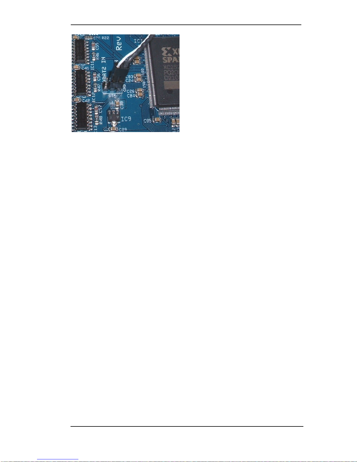
Connecting a TEB to the second ADAT In of a
HDSP 9652. Remove the jumper ST5, plug
DIGOUT of the TEB on both right and middle
pin of ST5.
6. Operation and Usage
Switch on the computer and boot the OS. The green LED on the TEB is lit when the power
supply is present. The red LED will be off as soon as the TEB receives a valid ADAT input sig-
nal via the DIG IN connector.
DIGI96 series
•Start the Settings dialog of the DIGI96/8 series, select the internal input (Input 'Internal'), set
Clock Mode to 'Master'.
•Connect the external device, which must be in clock mode slave, to the TDIF jack
•Connect the word clock output of the TEB with the word clock input of the TDIF device
•Verify that the clock select switch of the TEB is pressed
The Input Status must now show 'ADAT, 44.1 kHz, Internal' (or 48 kHz). In case 'No Lock' is
shown either the clock mode is not set up correctly, or the TEB is not connected correctly.
Hammerfall series and HDSP 9632/52
•Start the Settings dialog of the Hammerfall, select the internal input (AEB 'ADAT1 Internal'),
set Clock Mode to 'Master'.
•Connect the external device, which must be in clock mode slave, to the TDIF jack
•Connect the word clock output of the TEB with the word clock input of the TDIF device
•Verify that the clock select switch of the TEB is pressed
The Input Status in the field SyncCheck must now show 'ADAT1 In SYNC'. In case 'Lock' or 'No
Lock' is shown either the clock mode is not set up correctly, or the TEB is not connected cor-
rectly.
Clock Select Switch
The Clock Select switch of the TEB defines which reference clock is used by the TEB.
•Pushed: ADAT (PCI card)
•not pushed: TDIF (external device)
We recommend to set the switch according to the device being the current clock master. When
the external TDIF device is master: switch not pushed. With PCI card being master: switch
pushed.

User's Guide TEB
7
7. Word Clock
In the analogue domain one can connect any device to another device, a synchronization is not
necessary. Digital audio is different. Correct interpretation of digital audio data is dependent
upon a definite sample frequency. Signals can only be correctly processed or transferred be-
tween devices if these all share the same clock. Otherwise digital signals are misinterpreted,
causing distortion, clicks/crackle and even dropouts.
AES/EBU, SPDIF and ADAT optical are self-clocking (seen from a non-technical view TDIF
too, as word clock is embedded inside the TDIF cable), so an additional line for word clock
could be considered redundant. In practice however, using several devices at the same time
can cause problems. For example, if devices are connected in a loop without there being a
defined ‘master’ device, self-clocking may break down. Besides, the clocks of all devices must
be synchronized from a single source. Devices without SPDIF inputs (typically playback de-
vices such as CD-players) cannot be synchronized via self-clocking. Finally there are 'prob-
lematic' devices, which are nearly un-usable without a word clock attached anyway.
TDIF plays a special role in the world of digital audio formats. Although all necessary signals
are present inside the D-sub connector, most devices of the company Tascam require an addi-
tional word clock connection, providing a word clock signal shifted by 90°. Also many devices
with TDIF interface suffer from an incomplete clock design, causing clock noise by wrong syn-
chronisation when in master mode. The latter forced us to implement a clock select switch
which solves any compatibility problem.
In digital studios, synchronization requirements can be met by connecting all devices to a cen-
tral sync source. For instance, the master device could be a mixing desk, sending a reference
signal -word clock -to all other devices. However, this will only work if all the other devices
have word clock or sync inputs (e.g. some professional CD-players), allowing them to run as
slaves. This being the case, all devices will receive the same clock signal, so there is no fun-
damental reason for sync problems when they are connected together.
The TDIF format is especially critical with respect to word clock:
When the TEB is slave, no additional word clock connection is necessary. In case DA88
and/or DA38 are slave, the word clock output of the TEB has to be connected to the word
clock input of the first (master) recorder. When using more than one recorder a special sync
cable (Tascam part number PW-88S) is needed.
Word clock signals are usually distributed in the form of a network, split with BNC T-adapters
and terminated with resistors. We recommend using off-the-shelf BNC cables to connect all
devices, as this type of cable is used for most computer networks. You will find all the neces-
sary components (T-adapters, terminators, cables) in most electronics and/or computer stores.
To avoid voltage loss and reflections, both the cable itself and the terminating resistor at the
end of the chain should have an impedance of 75 Ohm. If the voltage is too low, synchroniza-
tion will fail. High frequency reflection effects can cause both jitter and sync failure.
The last device in a wordclock chain should be terminated using a T-adapter and a 75 Ohm
resistor (available as short BNC plug). Of course devices with internal termination do not need
T-adaptor and terminator plug.

User's Guide TEB
8
8. Double Speed
Sample rates above 48 kHz were not always taken for granted, and are still not widely used
because of the CD format (44.1 kHz) dominating everything. Before 1998 there were no re-
ceiver/transmitter circuits available that could receive or transmit more than 48 kHz. Therefore
a work-around was used: instead of two channels, one AES line only carries one channel, of
which the odd and even samples are being distributed to the former left and right channels. By
this, you get the double amount of data, i. e. also double sample rate. Of course in order to
transmit a stereo signal two AES/EBU ports are necessary then.
This transmission mode is being called Double Wire in the professional studio world, and is also
known as S/MUX in connection with the ADAT format. The DTRS recorder DA-98HR by Tas-
cam also uses this technique, which is called Dual Line here.
Not before February 1998, Crystal shipped the first 'single wire' receiver/transmitters that could
also work with double sample rate. It was then possible to transmit two channels of 96 kHz data
via one AES/EBU port.
Because the ADAT interface does not allow for sampling frequencies above 48 kHz (a limita-
tion of the interface hardware), the Hammerfall and HDSP 9652 automatically use a method
called Sample Spli. One channel's data is distributed to two channels according to the following
table:
Original 1234
DS Signal 1/2 3/4 5/6 7/8
As the transmission of double rate signals is done at standard sample rate (Single Speed) the
word clock output still delivers 44.1 kHz or 48 kHz.
The wordclock output as well as all ADAT and TDIF ports always operates in Single Speed
mode only. At 96 kHz, the word clock output will therefore be a 48 kHz signal.
The TDIF interface of the TDIF Expansion Board also supports the 'Double Wire' technique.
This allows a recording with up to 96 kHz at halfed track numbers with every (!) DTRS device.
9. Connector Pinout D-sub
The 25 pin D-sub connector is wired according to TDIF-1, version 1.1:
Signal
Out
1/2 Out
3/4 Out
5/6 Out
7/8 Out
LRCK
Out
EMPH
Out
FS0 Out
FS1
D-sub
1234518 619
Signal
In
FS1 In
FS0 In
EMPH
In
LRCK
In
7/8 In
5/6 In
3/4 In
1/2
D-sub
20 821 910 11 12 13
GND is connected to pins 7, 14, 15, 16, 17, 22, 23, 24, 25.

User's Guide TEB
9
10. Warranty
Each individual AEB undergoes comprehensive quality control and a complete test in a PC
environment at RME before shipping. The usage of high grade components allows us to offer a
full two year warranty. We accept a copy of the sales receipt as valid warranty legitimation.
RME’s replacement service within this period is handled by the retailer. If you suspect that your
card is faulty, please contact your local retailer. The warranty does not cover damage caused
by improper installation or maltreatment -replacement or repair in such cases can only be car-
ried out at the owner’s expense.
RME does not accept claims for damages of any kind, especially consequential damage. Liabil-
ity is limited to the value of the AEB. The general terms of business drawn up by Synthax Au-
dio AG apply at all times.
11. Appendix
RME news, driver updates and further product information are available on our website:
http://www.rme-audio.com
If you prefer to read the information off-line, you can load a complete copy of the RME website
from the RME Driver CD (in the \rmeaudio.web directory) into your browser.
Trademarks
All trademarks and registered trademarks belong to their respective owners. RME, DIGI96 and
Hammerfall are registered trademarks of RME Intelligent Audio Solutions. Alesis and ADAT are
registered trademarks of Alesis Corp. ADAT optical is a trademark of Alesis Corp. TDIF is a
trademark of TEAC Corp.
Copyright Matthias Carstens, 7/2002. Version 1.1
Although the contents of this User’s Guide have been thoroughly checked for errors, RME can not guarantee that it is correct
throughout. RME does not accept responsibility for any misleading or incorrect information within this guide. Lending or
copying any part of the guide or the RME drivers CD, or any commercial exploitation of these media without express written
permission from RME Intelligent Audio Solutions is prohibited. RME reserves the right to change specifications at any time
without notice.

User's Guide TEB
10
CE
This device has been tested and found to comply with the limits of the European Council Direc-
tive on the approximation of the laws of the member states relating to electromagnetic com-
patibility (EMVG) according to EN 55022 class B and EN50082-1.
FCC Compliance Statement
Certified to comply with the limits for a Class B computing device according to subpart J or part
15 of FCC rules. See instructions if interference to radio reception is suspected.
FCC Warning
This equipment has been tested and found to comply with the limits for a Class B digital de-
vice, pursuant to part 15 of the FCC rules. These limits are designed to provide reasonable
protection against harmful interference in a residential installation.
This device complies with part 15 of FCC rules. Operation is subject to the following two condi-
tions:
1. This device may not cause harmful interference
2. This device must accept any interference received, including interference that may cause
undesired operation.
However, there is no guarantee that interference will not occur in a particular installation. If this
equipment does cause harmful interference to radio or television reception, which can be de-
termined by turning the equipment off and on, the user is encouraged to try to correct the inter-
ference by one or more of the following measures:
•Reorient or relocate the receiving antenna
•Increase the seperation between the equipment and receiver
•Connect the equipment into an outlet on a circuit different from that to which the receiver is
connected
•Consult the dealer or an experienced radio/TV technician for help.
In order for an installation of this product to maintain compliance with the limits for a Class B
device, shielded cables must be used for the connection of any devices external to this prod-
uct.
Table of contents
Other RME Audio Sound Card manuals

RME Audio
RME Audio TCO HDSP/FF User manual

RME Audio
RME Audio DIGI96/8 PAD User manual

RME Audio
RME Audio DIGI32/8 User manual

RME Audio
RME Audio HDSPe RayDAT User manual

RME Audio
RME Audio Hammerfall HDSP 9632 User manual

RME Audio
RME Audio DIGI96/8 PAD User manual

RME Audio
RME Audio DIGI96 User manual

RME Audio
RME Audio DIGI96 User manual

RME Audio
RME Audio DIGI 96/8 PST User manual


