RMS Mors Smitt 1S24 User manual
Visit www.rmspl.com.au for the latest product information.
Due to RMS continuous product improvement policy this information is subject to change without notice. 1S24_Guide/Iss G/07/01/2019
1S24 User Guide
Arc Fault Monitoring System
relay monitoring systems pty ltd
Advanced Protection Devices
User Guide

1S24
User Guide
About This Manual
This User Guide covers all 1S24 relays manufactured from August 2017. Earlier relays do not
necessarily incorporate all the features described. Our policy of continuous development means that
extra features & functionality may have been added.
The 1S24 User Guide is designed as a generic document to describe the common operating
parameters for all relays built on this platform. Some relay applications are described but for specific
model information the individual “K” number Product / Test manuals should be consulted.
The copyright and other intellectual property rights in this document, and in any model or article produced from
it (and including any Registered or unregistered design rights) are the propertyof Relay Monitoring Systems
Pty Ltd. No part of this document shall be reproduced or modified or stored inanother form, in any data
retrieval system, without the permission of Relay Monitoring Systems Pty Ltd, nor shall any model or article
be reproduced from this document without consent from Relay Monitoring Systems Pty Ltd.
While the information and guidance given in this document is believed to be correct, no liability shall be
accepted for any loss or damage caused by any error or omission, whether such error or omission is the
result of negligence or any other cause. Any and all such liability is disclaimed.
Contact Us
Relay Monitoring Systems Pty Ltd 2006-2013
6 Anzed Court • Mulgrave 3170 • AUSTRALIA
Phone 61 3 8544 1200 • Fax 61 3 8544 1201
Email rms@rmspl.com.au • Web www.rmspl.com.au
To download a PDF version of this guide:
http://rmspl.com.au/wordpress/wp-content/uploads/2015/08/1S24_User_Guide.pdf

Visit www.rmspl.com.au for the latest product information.Page
Due to RMS continuous product improvement policy this information is subject to change without notice. 1S24_Guide/Iss G/07/01/2019
How this Guide is Organised
This guide is divided into three parts:
Part 1 Overview
Part 2 Documentation
Part 3 Application
Part
1

Visit www.rmspl.com.au for the latest product information.Page
Due to RMS continuous product improvement policy this information is subject to change without notice. 1S24_Guide/Iss G/07/01/2019
Documentation
Technical Bulletin
The detailed technical attributes, functional description & performance specifications for the 1S24
are described in the product Technical Bulletin. For the most up to date version go to:
http://rmspl.com.au/product/1s24/
http://rmspl.com.au/product/1s30/
http://rmspl.com.au/product/1s40/
The order of precedence for product information is as follows:
•Product Test Manual (PTM)
•Technical Bulletin
•User Guide
User Guide
This User Guide covers all 1S24 relay versions & describes the generic features & attributes
common across all versions.
Different relay versions are required to cater for varying customer requirements such as auxiliary
voltage range, I/O configuration, case style, relay functionality etc.
The product ordering code described in the Technical Bulletin is used to generate a unique
version of the relay specification & is called a Type Number. This code takes the form 1S24Kxx
where the Kxx is the “K” or version number. For a complete description of the RMS “K” number
system refer to: www.rmspl.com.au/handbook/parta3.pdf
Product Test Manual
Each 1S24 version has a specific PTM which provides details on the unique attributes of the
relay. Each PTM includes the following information:
•Specific technical variations from the standard model if applicable
•Wiring diagram
If you require a copy of the PTM for an RMS product the following options are available:
•Check the RMS web site at: http://rmspl.com.au/product-test-manuals/
•Contact RMS or a representative & request a hard copy or PDF by email.
Part
2

Page 1
Visit www.rmspl.com.au for the latest product information Page
Due to RMS continuous product improvement policy this information is subject to change without notice. 1S24_Guide/Iss G/07/01/2019
Application
1S30 Sensors........................................................................................................................................4
Sensor Placement.................................................................................................................................6
Sensor Mounting ...................................................................................................................................6
Example Sensor Placement..................................................................................................................7
1S40 Linear Sensors...........................................................................................................................11
1S40 Linear Sensor Assembly............................................................................................................13
1S40 Linear Sensor Compartment Fixing...........................................................................................14
1S24 Connection diagrams.................................................................................................................15
Linear Sensor Connections.................................................................................................................17
Example Schematic –Direct Arc Trip Only Application ......................................................................18
Example Schematic –Current Checked Arc Trip Application.............................................................19
Terminal Layout and Module Dimensions...........................................................................................20
Surface or Din Rail Mounting................................................................................................................... 20
Horizontal or Vertical Flush Mounting......................................................................................................23
Custom Labels.....................................................................................................................................26
Physical Connections..........................................................................................................................27
IEC61850 Communication Topologies................................................................................................28
IP Addressing......................................................................................................................................29
Web Browser Session.........................................................................................................................30
Relay Build ..........................................................................................................................................32
IP Configuration...................................................................................................................................32
Arc Configuration.................................................................................................................................33
State........................................................................................................................................................34
Trip 1.......................................................................................................................................................34
Trip 2.......................................................................................................................................................34
Zone........................................................................................................................................................34
Linear Sensor Configuration................................................................................................................35
Arc Status............................................................................................................................................36
State........................................................................................................................................................36
Flag .........................................................................................................................................................36
Count....................................................................................................................................................... 37
Summary of 1S24 SARC Configuration..............................................................................................37
Application Example............................................................................................................................38
Arc Fault Scheme................................................................................................................................39
Part
3
Sensor Installation.......................................................................................................... 4
Scheme Wiring.............................................................................................................. 15
Communications........................................................................................................... 27
1S24 Arc Fault Monitor Configuration ........................................................................ 30
Example IEC61850 Substation Configuration ............................................................ 38

Page 2
Visit www.rmspl.com.au for the latest product information Page
Due to RMS continuous product improvement policy this information is subject to change without notice. 1S24_Guide/Iss G/07/01/2019
1S24 SARC Allocation ........................................................................................................................41
Protection Zone Tripping.....................................................................................................................41
1S24 Source Arc Fault Detector Points ..............................................................................................42
7SR22 Single Point Input GGIO Allocation.........................................................................................42
Creating an IEC61850 Project.............................................................................................................42
Populating IEDs In the IEC 61850 Project..........................................................................................45
System Configuration –Network View................................................................................................51
System Configuration –Link View.......................................................................................................54
Creating the 1S24 .cid File..................................................................................................................58
The .cid File.........................................................................................................................................59
FTP 1S24.cid File................................................................................................................................59
Rebooting the 1S24 with the New 1S24.cid File.................................................................................61
Logic Configuration .............................................................................................................................65
User Output Allocation ........................................................................................................................65
Current Check Logic............................................................................................................................66
Binary Output Allocation for Circuit Breaker Tripping..........................................................................67
Device Synchronization.......................................................................................................................67
Front Layout ........................................................................................................................................68
Power Up.............................................................................................................................................68
System Status .....................................................................................................................................69
Service Alarm......................................................................................................................................69
Arc Sensor Indicators..........................................................................................................................70
Arc Sensor Circuit Supervision............................................................................................................70
Arc Trip................................................................................................................................................70
Global Arc Block..................................................................................................................................70
Flag Reset...........................................................................................................................................71
Reboot.................................................................................................................................................71
Reset to Factory Default......................................................................................................................72
Introduction..........................................................................................................................................73
Firmware Package ..............................................................................................................................73
License file not valid or present...........................................................................................................75
Invalid IP Address Specified in ICD File..............................................................................................77
System Status .....................................................................................................................................78
Commissioning Preliminaries..............................................................................................................79
Site Commissioning Verification Checklist..........................................................................................80
System Power Up....................................................................................................................................80
Sensor Failure Alarm Verification............................................................................................................81
Arc Trip Testing....................................................................................................................................... 81
Sensor Failure Alarm Trouble Shooting...................................................................................................82
ARC Trip Trouble Shooting......................................................................................................................83
1S24 IEC61850 Configuration...................................................................................... 59
Subscribing Reyrolle 7SR22 IED Configuration......................................................... 65
Monitor Indications....................................................................................................... 68
Firmware Update........................................................................................................... 73
Trouble Shooting.......................................................................................................... 75
Commissioning............................................................................................................. 79

Page 3
Visit www.rmspl.com.au for the latest product information Page
Due to RMS continuous product improvement policy this information is subject to change without notice. 1S24_Guide/Iss G/07/01/2019
General Ethernet Communications Trouble Shooting .............................................................................83
IEC61850 GOOSE Message Trouble Shooting.......................................................................................84
Interpreting Vx Auxiliary Supply or Relay Healthy Indications.................................................................84
Using IED SCOUT IEC61850 GOOSE Message Trouble Shooting........................................................86
Page 4
Visit www.rmspl.com.au for the latest product information Page
Due to RMS continuous product improvement policy this information is subject to change without notice. 1S24_Guide/Iss G/07/01/2019
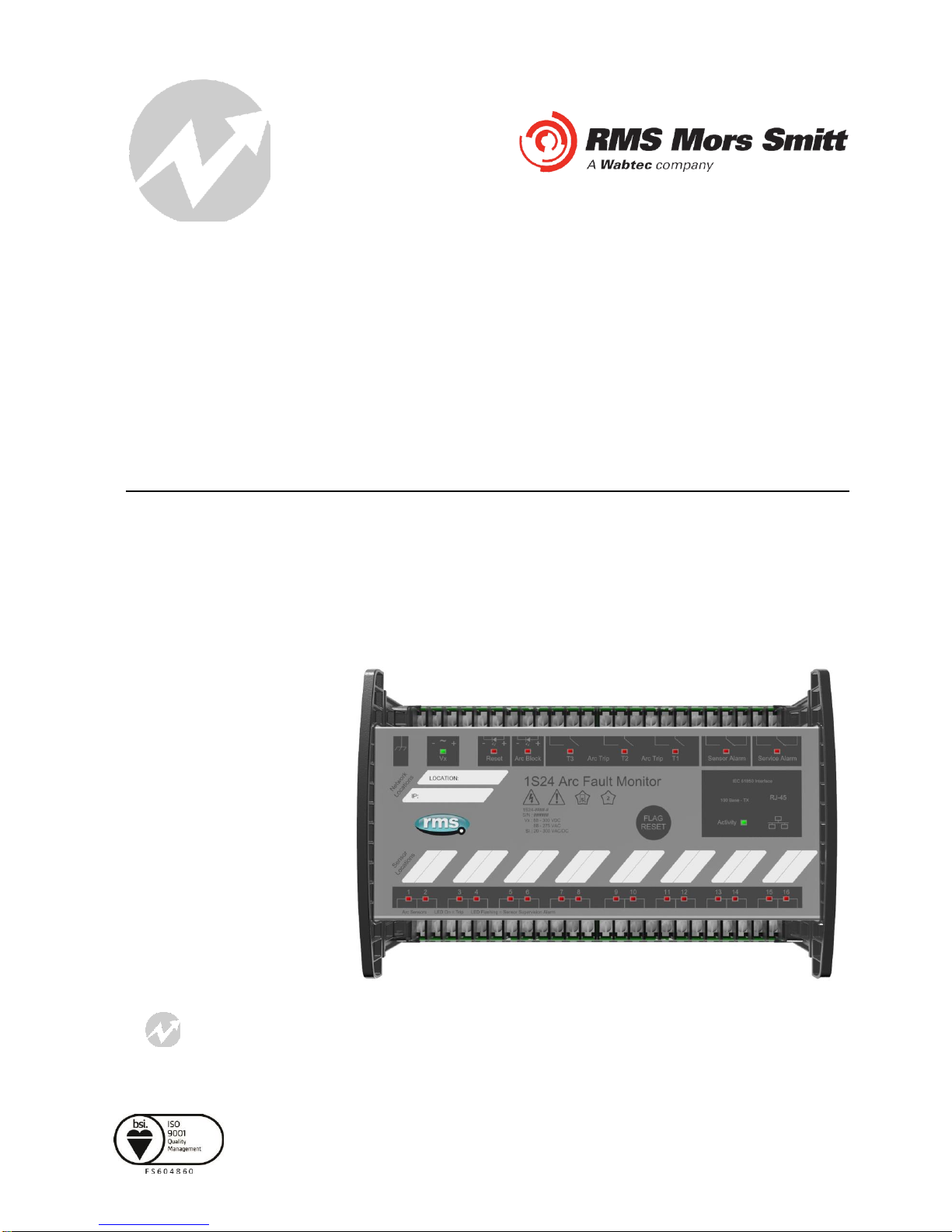
Sensor Installation
1S30 Sensors
The 1S30 sensor is available as a single detector or dual detector package.
The 1S30A single detector version is depicted below showing the location of the detection window
and the approximate coverage zone:
The recommended spacing for the 1S30A single detectors is approximately 5 - 6 m to ensure
adequate detection overlap.
3m
Detection window
Coverage Zone
5 - 6 m

Page 5
Visit www.rmspl.com.au for the latest product information Page
Due to RMS continuous product improvement policy this information is subject to change without notice. 1S24_Guide/Iss G/07/01/2019
The 1S30B Dual detector version provides an additional detection window for dual zones of coverage
as depicted below :
The recommended spacing for the 1S30B single detectors is approximately 5 - 6 m to ensure
adequate detection overlap, this combination provides an overall coverage zone of approximately 10 -
12 m.
Detection windows
6m
10 - 12m

Page 6
Visit www.rmspl.com.au for the latest product information Page
Due to RMS continuous product improvement policy this information is subject to change without notice. 1S24_Guide/Iss G/07/01/2019
The 1S30A and 1S30B sensors may also be mixed to provide various coverage combinations, again
spacing’s of approximately 5 - 6 m should beobserved to ensure adequate detection overlap.
Sensor Placement
Sensors need to be mounted to provide full coverage of the switchgear cubicles to be protected.
Where the protected zone is larger than the sensor coverage then the use of multiple sensors is
required.
Precise positioning of the sensors is generally not required as the light caused by the arc is reflected
from the walls.
Sensor Mounting
The 1S30 is suitable for flush panel mounting in a number of configurations, for further
information on mounting arrangements and mounting hardware refer to the 1S30 Technical
Bulletin.
10 - 12m
Page 7
Visit www.rmspl.com.au for the latest product information Page
Due to RMS continuous product improvement policy this information is subject to change without notice. 1S24_Guide/Iss G/07/01/2019
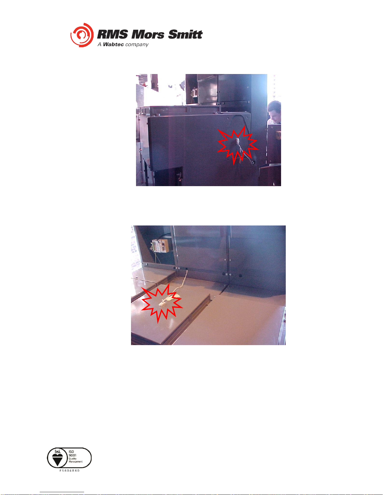
Example Sensor Placement
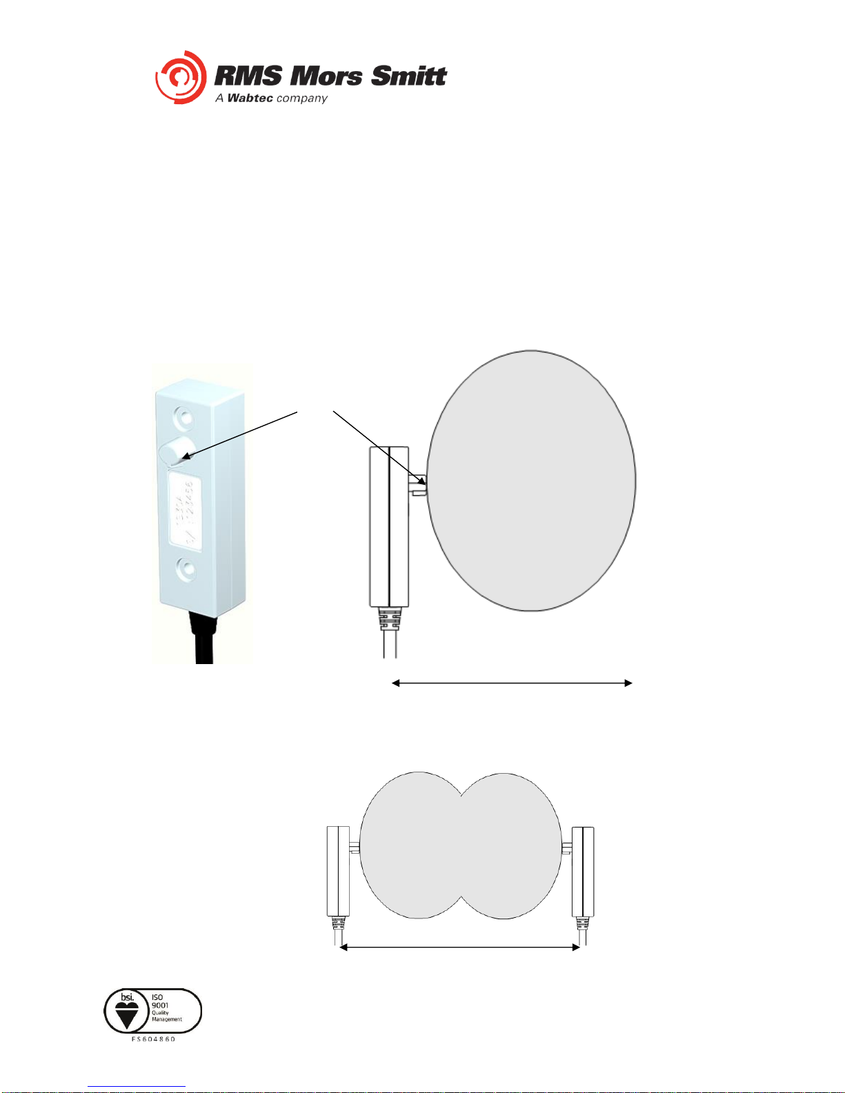
The following are some typical examples of sensor placement.
Sensor placement inside CB racking chamber
Sensor placement inside busbar chamber
Page 8
Visit www.rmspl.com.au for the latest product information Page
Due to RMS continuous product improvement policy this information is subject to change without notice. 1S24_Guide/Iss G/07/01/2019
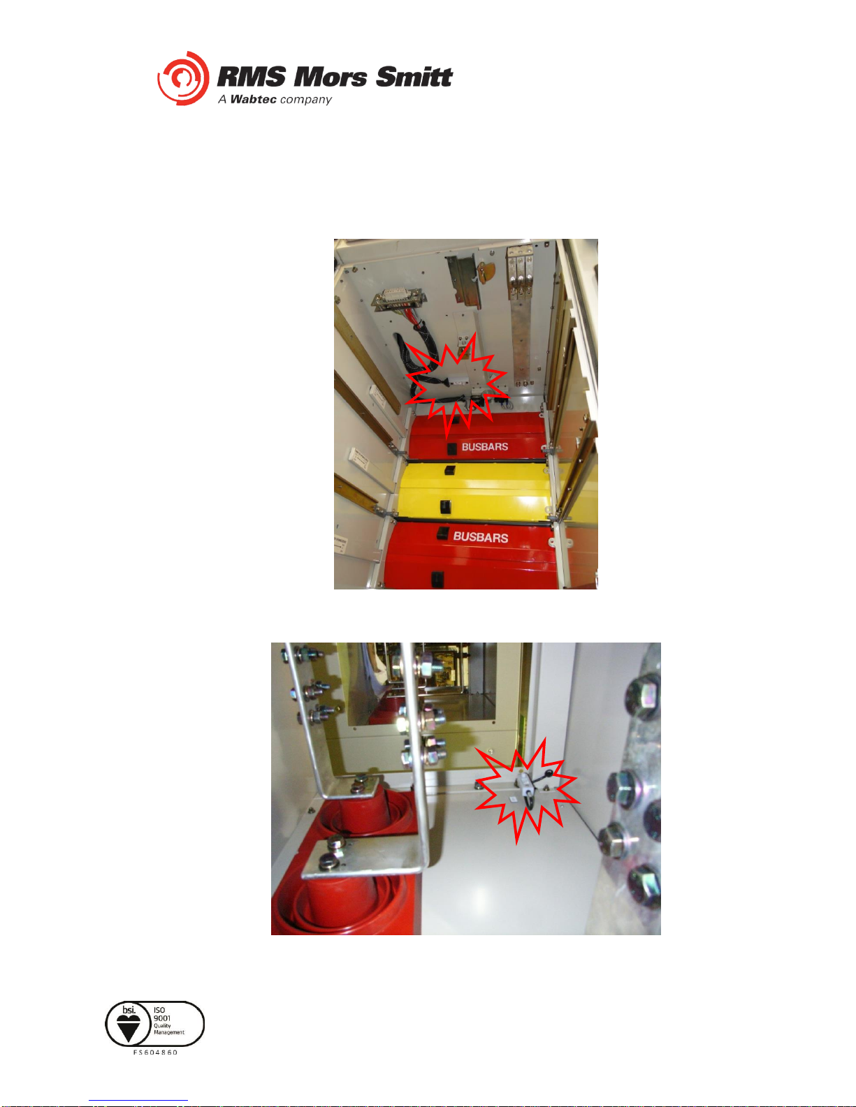
Sensor placement inside cable termination chamber
Sensor placement for switchgear Busbar coverage (External through Hole Detector)

Page 9
Visit www.rmspl.com.au for the latest product information Page
Due to RMS continuous product improvement policy this information is subject to change without notice. 1S24_Guide/Iss G/07/01/2019
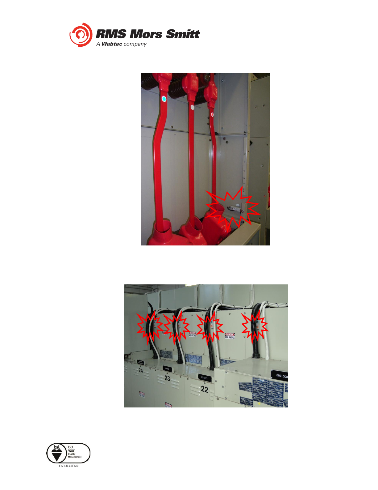
Sensor placement near Low Voltage Contactorfor a Variable Speed Drive
Sensor placement for Switchgear cable termination chamber (External through Hole Detector)
Page 10
Visit www.rmspl.com.au for the latest product information Page
Due to RMS continuous product improvement policy this information is subject to change without notice. 1S24_Guide/Iss G/07/01/2019
Sensor placement for endof Bus chamber (External through Hole Detector)
Sensor placement for Switchgear cable termination chamber (External through Hole Detector)

Page 11
Visit www.rmspl.com.au for the latest product information Page
Due to RMS continuous product improvement policy this information is subject to change without notice. 1S24_Guide/Iss G/07/01/2019
1S40 Linear Sensors
The 1S40 linear sensor may be applied to protect large volumes where multiple point sensors would
otherwise be required.
A separate 1S40 linear sensor is required for each segregated protection zone.
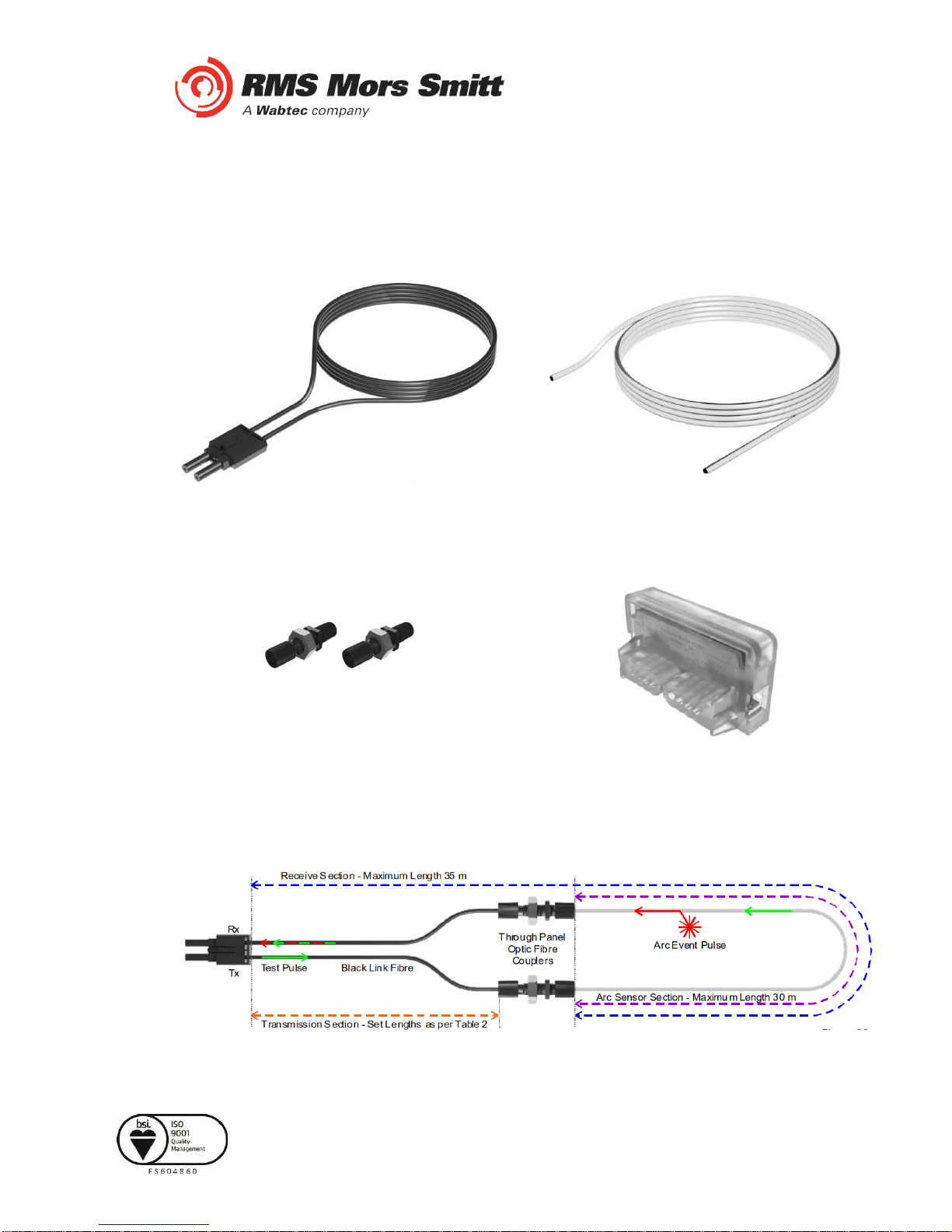
The linear sensor kits provide both a black link fibre and a translucent arc sensor fibre. The translucent
fibre is located within the detection zone and black link fibres allow routing of the linearsensor back to
the relay.
Translucent and black link fibres are joined through the use of optical fibre couplers. An optical fibre
duplex connector is utilised for relay connection
For the most effective coverage it is preferable to loop the translucent fibre within the monitored
compartment or chamber as shown in the diagrams above. A light intensity of >7,500 Lux over a
length of 300mm is required to cause an arc trip.
Un-monitored CompartmentMonitored Compartment
Arc Fault Relay
Fibre Sensor
inputs
Black Link Fibre
Translucent Sensor Fibre
Optical fibre
couplers
Optical fibre
duplex
connector
Page 12
Visit www.rmspl.com.au for the latest product information Page
Due to RMS continuous product improvement policy this information is subject to change without notice. 1S24_Guide/Iss G/07/01/2019
The 1S40kit comprises of lengths of black link fibre (pre-terminated with a duplex connector for relay
connection), unterminated translucentfibre, 2 x optical fibre couplers and a fibre optic fibre cutter.
Black Link FibreAssembly
Translucent Sensor Fibre
Optic Fibre Couplers
Optic Fibre Cutter
The individual components are combined per the diagram below :
Page 13
Visit www.rmspl.com.au for the latest product information Page
Due to RMS continuous product improvement policy this information is subject to change without notice. 1S24_Guide/Iss G/07/01/2019
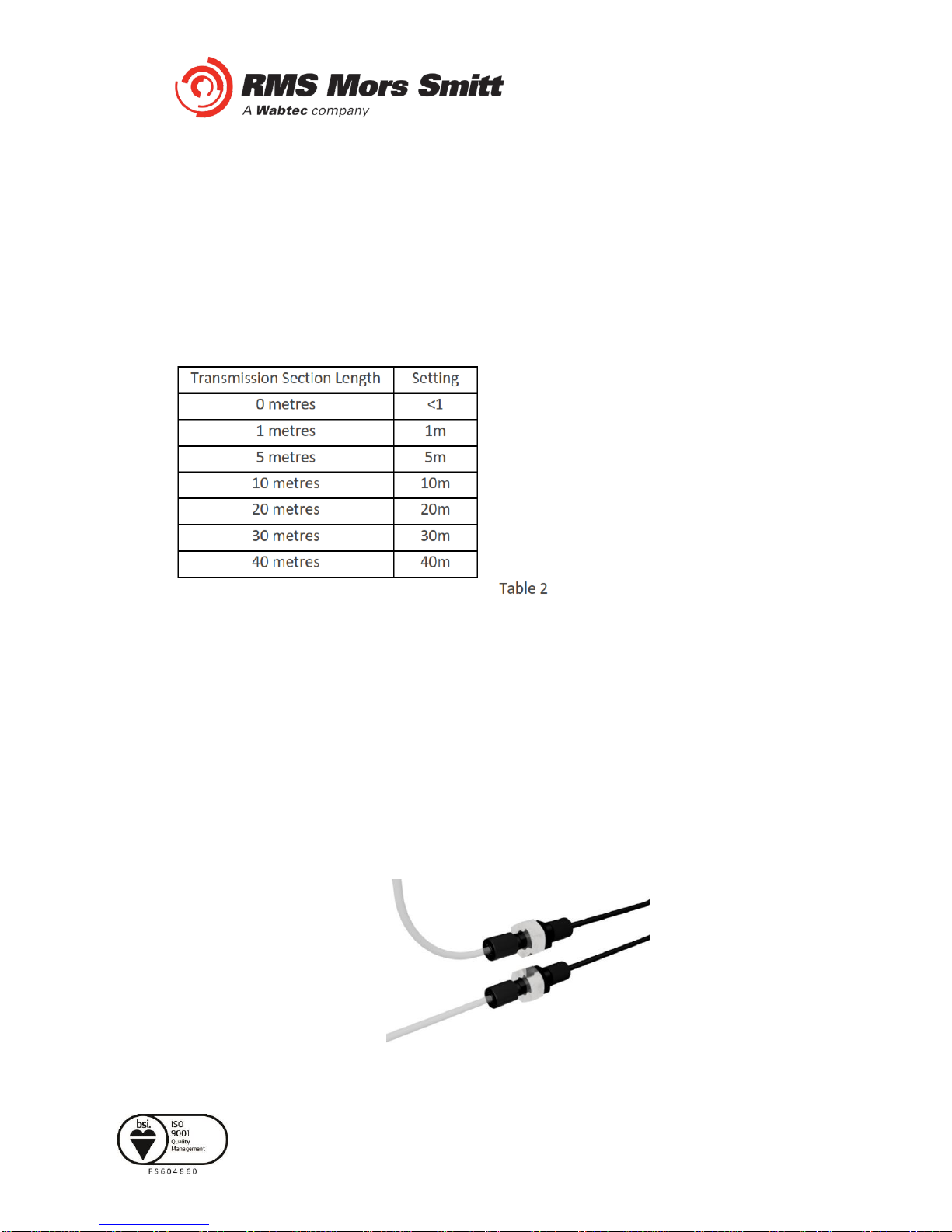
The following sensor dimensioning criteria must be satisfied for the arcfault relay linear sensor input to
self calibrate and function correctly :
1. Transmission Section (section of clad fibre from relay Tx connection) to optic fibre coupler
must be 40m and cut tothe set lengths in Table 2 within a tolerance of ±10%
2. Receive Section (section of bare and clad fibre back to the relay Rx connection) must be
35m
3. Arc Sensor Section (section of bare fibre) must be30m
The chosen Transmission Section Length must also be configured in the 1S24 Fibre Loop Sensor
configuration screen –refer toLinear Sensor Configuration.
1S40 Linear Sensor Assembly
Once the lengths of black link fibre and translucent sensor fibre have been determined cut them using
the optic fibre cutter provided –other cutting tools must not be used asthis will lead to excessive
attenuation within the fibre and result in incorrect operation.
The cut sections of black link fibre and translucentfibre are coupled using the provided optic fibre
couplers. Slide the cut lengths completely into the couplers and hand tighten the coupler cinch nuts
taking care not to strip the cinch nut threads.
Coupled Black Link and Translucent Sensor Fibres

Page 14
Visit www.rmspl.com.au for the latest product information Page
Due to RMS continuous product improvement policy this information is subject to change without notice. 1S24_Guide/Iss G/07/01/2019
1S40 Linear Sensor Compartment Fixing
The optic fibrecouplersmaybe positioned and held in place withthe provided fixing nuts at a
compartment interface.
The optic fibres may beretained using cable ties or silicon adhesive. When using silicon adhesive no
more than 10% of the sensor fibre shall be masked by the silicon.
Care should betaken not to apply excessive force when fixing the 1S40 sensor. Excessive force or
rough handling may result in damage to the fibre sensor.
Care should also be taken when bending the 1S40 sensor to ensure that the minimum bending radius
of 50mm is adhered to.
Page 15
Visit www.rmspl.com.au for the latest product information Page
Due to RMS continuous product improvement policy this information is subject to change without notice. 1S24_Guide/Iss G/07/01/2019
Scheme Wiring
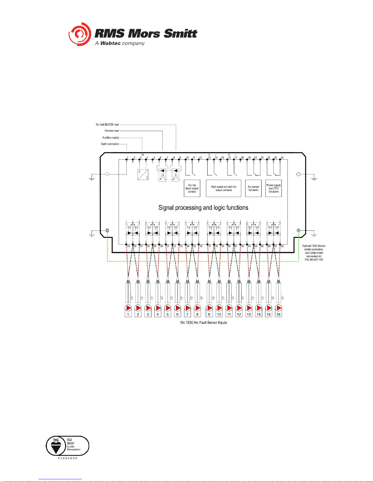
1S24 Connection diagrams
2 Trip Output Version

Page 16
Visit www.rmspl.com.au for the latest product information Page
Due to RMS continuous product improvement policy this information is subject to change without notice. 1S24_Guide/Iss G/07/01/2019
3 Trip Output Version
The above diagrams show the 1S24 connections.
The connected sensor inputs need to be enabled and unused inputs disabled via the Web
browser configuration tool. This is essential to:
•Allow connected sensor inputs to operate for an ARC Fault
•Allow connected sensor inputs to be supervised
•Ensure unconnected sensor inputs do not indicate an Arc sensor Alarm condition
Table of contents


