Tricor PRO Series User manual

PRO Series | Function Manual
TRICOR®
Coriolis Mass Flow Meter –TCD 9x00 Profibus

Version
TCD Electronics | Function Manual | Version: TCD_PROFI_S_EN_200326_E003
2
Manual-Version
TCD_PROFI_S_EN_200326_E003
This document is supplied as standard in electronic media with the device. Latest version can be
downloaded at www.tricorflow.com.
NOTE:
This manual applies to the Coriolis Flow Meter with the brand TRICOR.

Index
TCD Electronics | Function Manual | Version: TCD_PROFI_S_EN_200326_E003
3
Index
1. LEGAL
INFORMATION
......................................................................................................... 5
1.1.
Warning
notice
system
............................................................................................................................5
1.2. Qualified Personnel ....................................................................................................................................5
1.3. Proper use of TRICOR products ..................................................................................................................6
1.4. Disclaimer of Liability..................................................................................................................................6
2. INTRODUCTION..................................................................................................................... 7
2.1. Purpose of this documentation..................................................................................................................7
2.2. Document history .......................................................................................................................................7
3. COMMUNICATION ................................................................................................................ 8
3.1. Features......................................................................................................................................................8
3.2. Installation in hazardous area ....................................................................................................................8
3.3. Profibus.......................................................................................................................................................8
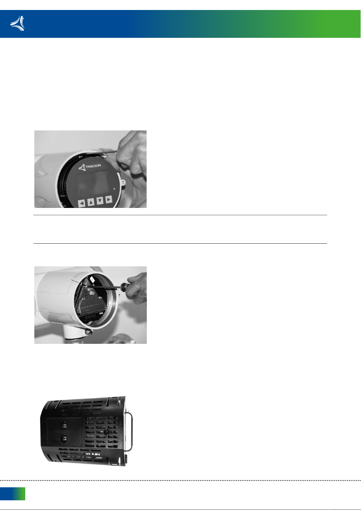
3.4. Changing Profibus termination at the transmitter cassette.....................................................................10
3.5. Connecting the Profibus (CH1) .................................................................................................................11
3.6. Installation check......................................................................................................................................12
3.7. Cyclic services ...........................................................................................................................................12
3.8. Acyclic communication.............................................................................................................................13
3.8.1. Slot 0, Physical Block.................................................................................................................................13
3.8.2. Slot 1: Analog Input block –Mass flow.....................................................................................................18
3.8.3. Slot 1: Transducer Block ...........................................................................................................................19
3.8.4. Slot 2: Analog Input block –Density.........................................................................................................29
3.8.5. Slot 3: Analog Input block –Medium temperature..................................................................................30
3.8.6. Slot 4: Totalizer block 1.............................................................................................................................30
3.8.7. Slot 5: Totalizer block 2.............................................................................................................................33
3.8.8. Slot 6: Analog Input block –Volume flow.................................................................................................36
3.8.9. Slot 7: Analog Input block –Fractional flow A block ................................................................................36
3.8.10. Slot 8: Analog Input block –Fractional flow B block ................................................................................37
3.8.11. Slot 9: Analog Input block –Fractional flow % A block.............................................................................38
3.8.12. Slot 10: Analog Input block –Fractional flow % B block...........................................................................38
3.8.13. Slot 11: Analog Input block –Standard volume flow ...............................................................................39
3.8.14. Slot 12: Analog Input block –Frame temperature ...................................................................................40
3.8.15. Slot 12: Analog Input block –Frame temperature ...................................................................................40
3.8.16. Slot 13: Totalizer block 3...........................................................................................................................41
3.8.17. Slot 14: Control commands (Manufacturer Specific) ...............................................................................44
3.8.18. Dosing block, Slot 15.................................................................................................................................45

Index
TCD Electronics | Function Manual | Version: TCD_PROFI_S_EN_200326_E003
4
3.9. Access Control ..........................................................................................................................................46
3.10. Alarm, error, an system messages............................................................................................................47
3.10.1. Introduction..............................................................................................................................................47
3.10.2. Diagnosis Response ..................................................................................................................................47
4. CABLE SPECIFICATIONS ....................................................................................................... 49
5. LISTINGS.............................................................................................................................. 50
5.1. List of Figures............................................................................................................................................50
5.2. List of Tables .............................................................................................................................................50

Legal information
TCD Electronics | Function Manual | Version: TCD_PROFI_S_EN_200326_E003
5
1.Legal
information
1.1.
Warning
notice
system
This manual contains notices you have to observe in order to ensure your personal safety, as well as to
prevent damage to property. The notices referring to your personal safety are highlighted in the manual by
a safety alert symbol, notices referring only to property damage have no safety alert symbol. These notices
shown below are graded according to the degree of danger. All names identified by ® are registered
trademarks. The remaining trademarks in this publication may be trademarks whose use by third parties for
their own purposes could violate
the rights of the owner.
DANGER!
indicates that death or severe personal injury will result if proper precautions are not taken.
WARNING!
indicates that death or severe personal injury may result if proper precautions are not taken
CAUTION!
indicates that minor personal injury can result if proper precautions are not taken
NOTE:
indicates that property damage can result if proper precautions are not taken
If more than one degree of danger is present, the warning notice representing the highest degree of danger
will be used. A notice warning of injury to persons with a safety alert symbol may also include a warning
relating to property damage.
1.2. Qualified Personnel
The product/system described in this documentation may be operated only by personnel qualified for the
specific task in accordance with the relevant documentation, in particular its warning notices and safety
instructions. Qualified personnel are those who, based on their training and experience, are capable of
identifying risks and avoiding potential hazards when working with these products/systems.

Legal information
TCD Electronics | Function Manual | Version: TCD_PROFI_S_EN_200326_E003
6
1.3. Proper use of TRICOR products
Note the following:
WARNING!
TRICOR products may only be used for the applications described in the relevant technical documentation.
If products and components from other manufacturers are used, these must be recommended or approved
by TRICOR. Proper transport, storage, installation, assembly, commissioning, operation and maintenance
are required to ensure that the products operate safely and without any problems. The permissible
ambient conditions must be complied with. The information in the relevant documentation must be
observed.
1.4. Disclaimer of Liability
We have reviewed the contents of this publication to ensure consistency with the hardware and software
described. Since variance cannot be precluded entirely, we cannot guarantee full consistency. However, the
information in this publication is reviewed regularly and any necessary corrections are included in
subsequent editions.

Introduction
TCD Electronics | Function Manual | Version: TCD_PROFI_S_EN_200326_E003
7
2.Introduction
2.1. Purpose of this documentation
This
manual
contains all information needed to integrate the process instruments into
a
communications
network. The
manual
is aimed at control system
designers, system
integrators,
instrument
engineers.
In order to operate safety and for more detailed information you need the product
specific
manual. Available
for
download
from Flow
documentation
(
www.tricorflow.com).
This
manual
applies to the
TRICOR TCD 9x00
transmitter Profibus DP/PA version only.
The
TCD 9x00 transmitter is intended to be used for TCMP and TCMQ series.
In order to operate a Coriolis flow meter, you also need Operating Instructions. See
Flow
documentation
(
www.tricorflow.com).
2.2. Document history
The following table shows major changes in the documentation compared to the previous edition.
Edition
Note
03/2020
First edition

Communication
TCD Electronics | Function Manual | Version: TCD_PROFI_S_EN_200326_E003
8
3.Communication
3.1. Features
The device provides the following
features:
•
PROFIBUS
DP
communication
up to 12 Mbit/s
•Automatic baud rate
adaption
•
PROFIBUS
PA
communication
•Automatic baud rate
adaption
•Cyclic
communication
•Support of
PROFIBUS
PA Profile for Process Control Devices V4.0 and
V3
•Automatic GSD
adaption
•Support of up to 15 modules (process values and control values), in cyclic
communication
•
PROFIBUS
clock
synchronization
by
master
3.2. Installation in hazardous area
The PROFIBUS DP module is not allowed for use in hazardous areas.
The PROFIBUS PA module is allowed for use in hazardous areas.
3.3. Profibus
The transmitter has a modular design with discrete, replaceable electronic modules and connection boards
to maintain separation between functions and facilitate field service. All modules are fully traceable and
their provenance is included in the transmitter setup.
The bus termination can be activated via a switch internal in the transmitter. The bus termination switch is
set to off by default. If the internal switch is not used for termination an external separate bus terminator
must be installed. The internal switch is located on the transmitter PCBA module.

Communication
TCD Electronics | Function Manual | Version: TCD_PROFI_S_EN_200326_E003
9
Fig. 1: Transmitter exploded view
①
Housing cover with viewing window
⑫
Transmitter housing
②
Display (HMI)
⑬
Terminal space
③
HMI data cable
⑭
Power supply terminal protection cover
④
SD card
⑮
Housing cover
⑤
DIP switch (for custody transfer)
⑯
Wiring tool
⑥
DIP switch (for HART and Modbus)
⑰
I/O cassette (optional)
⑦
HMI port
⑱
I/O configuration keys (optional)
⑧
USB service port
⑲
M12 socket
(version dependent for TCD 9200)
⑨
Transmitter cassette
⑳
Sensor module
⑩
Power supply module
㉑
Cover lock
⑪
Cable entry

Communication
TCD Electronics | Function Manual | Version: TCD_PROFI_S_EN_200326_E003
10
3.4. Changing Profibus termination at the transmitter cassette
To change the termination of the Profibus, it is required to remove the transmitter module out of the
transmitter. This can be done following below instructions.
1. Isolate the device from power.
2. Unscrew the locking screw of the display and remove the display lid
using
a wrench bar if
necessary.
3. Carefully remove display and cable
plug.
NOTE:
Use a screwdriver to release the display as shown in photo below. The display is held in place with three
clips.
4. Remove the screw holding the transmitter cassette. Pull out the transmitter cassette.
5.
Changing
termination at the transmitter cassette, by
changing
the position of the
dip
switches as
below.
6. All off: no
termination
7. All on: termination
activated

Communication
TCD Electronics | Function Manual | Version: TCD_PROFI_S_EN_200326_E003
11
8. Reinstall the transmitter
cassette.
9. Reinstall the display and display cable, incl. the
O-ring.
Mount the O-ring by pulling it over the
display
lid.
Return the device to operation
1. Restore power to the
device.
2. Check that the device starts up as expected. If possible watch the display during
startup
and observe
the device versions for
consistency.
3.5. Connecting the Profibus (CH1)
WARNING!
Warnings provide very important information for the correct usage of the equipment. Not observing the
warnings may lead to danger for the equipment and to danger for health and life of the user.
1.
Remove
cap and ferrule from cable gland and slide onto
cable.
2. Push cable through open gland and cable
path.
3. Restore ferrule and tighten cap to lightly hold cable in
place.
4. Signal cable screen is folded back over outer sheath and
grounded
beneath cable
clamp.
5. Connect wires to terminals using wiring tool, field mount
transmitter
6. Tighten cable gland.
①
In + (B)
②
In - (A)
③
Out + (B)
④
Out - (A)
Fig. 2: Profibus DP/PA

Communication
TCD Electronics | Function Manual | Version: TCD_PROFI_S_EN_200326_E003
12
3.6. Installation check
•Make sure the installation
guidelines
provided by the "Wiring & Installation
Application
Guide" on Profibus Installation guide
(
http://www.profibus.com/download/installation-
guide/) are
followed.
•Make sure the wiring
requirements
for the device are
met.
•
Make sure all connectors are properly
tightened.
3.7. Cyclic services
Below is an overview of which cyclic services and parameter update time the device provides. Input
(Master view) is defined as values from the flowmeter to the master. Output (Master view) is defined as
values from the master to the flowmeter. Update time is the interval the flowmeter updates the
parameters.
Parameter
name
Update
time
Input
(Master
view)
Mass
flow
10 msec
Density
10 msec
Medium
temperature
30 msec
Totalizer 1 (single and double precision
10 msec
Totalizer 2 (single and double precision)
30 msec
Fractional flow
A
10 msec
Fractional flow
B
30 msec
Fractional flow %
A
30 msec
Fractional flow %
B
30 msec
Standard volume
flow
10 msec
Frame
temperature
30 msec
Totalizer 3 (single and double precision)
30 msec
Control
status:
•Zero point adjustment
active
•Outputs
forced
•Process values
frozen
10 msec
Dosing:
•Zero point adjustment
active
•Dosing
status
•Dosing output
(analogue/
discrete)
30 msec
Output
(Master
view)
Dosing
control:
•Start
•Stop
•Pause
•Resume
•Clean
Start zero point
adjustment
Force
/
unforce
outputs
Control totalizer
1
Control totalizer
2
Control totalizer
3
Tab. 1: Cyclic services

Communication
TCD Electronics | Function Manual | Version: TCD_PROFI_S_EN_200326_E003
13
3.8. Acyclic communication
Acyclic Addressing
Each parameter in a PROFIBUS slave is mapped to an address specified by slot and index. The slot number
refers to an array of data. The index tells you where in the array the data you want starts.
Slot
Index Range
Block
0
16…68
Physical block
1
16…37
Analog input block - Mass flow
68…138
Transducer block
2
16…37
Analog input block - Density
3
16…37
Analog input block - Medium Temperature
4
16…32
Totalizer block 1
5
16…32
Totalizer block 2
6
16…37
Analog input block - Volume Flow
7
16…37
Fraction Flow A block (Manufacturer Specific)
8
16…37
Fraction Flow B block (Manufacturer Specific)
9
16…37
Fraction Flow % A block (Manufacturer Specific)
10
16…37
Fraction Flow % B block (Manufacturer Specific)
11
16…37
Analog input block - Standard volume flow
12
16…37
Analog input block - Frame temperature
13
16…32
Totalizer block 3
14
16…19
Binary commands (Manufacturer Specific)
15
16…33
Dosing block (Manufacturer Specific)
30 …255 Used for direct access of MODBUS registers.
Tab. 2: Acyclic data
3.8.1. Slot 0, Physical Block
Index
Parameter name
Data type
[size]
Access
Annotation
16
BLOCK_OBJECT
DS-32
Read
only
Constant block information
17
CURRENT_MODE
Unsigned8
Read
only
Follows the target mode
8: Automatic
128: Out of service
22
TARGET_MODE
Unsigned8
Read
Write
Desired device mode that is taken over by the
CURRENT‐ MODE parameter:
Coding:
8: Automatic
128: Out of service, sets all function blocks into out
of service
23
OrderID
Visible-
String(20)
Read
only
Order ID no.
24
Software_Revision
Visible-
String(20)
Read
only
String representation of the product firmware
version

Communication
TCD Electronics | Function Manual | Version: TCD_PROFI_S_EN_200326_E003
14
Index
Parameter name
Data type
[size]
Access
Annotation
25
Hardware_Revision
Visible-
String(20)
Read
only
String representation of the product hardware
version
26
VendorID
Unsigned16
Read
only
Unsigned16 identifier of the product manufacturer
27
DEVICE_ID
Visible-
String(20)
Read
only
Product name
28
IM_Serial_Number
Visible-
String(20)
Read
only
Serial number
29
DIAGNOSIS
Octet-
String(20)
Read
only
Device global alarm information
Byte 0: Bits 0…7 reserved
Byte 1: Bits 0…2 reserved
Bit 3 warm start (restart)
Bit 4 cold start (application
reset)
Bit 5 maintenance required
Bits 6…7 reserved
Byte 2: Bit 0 maintenance alarm
Bit 1 maintenance demanded
Bit 2 function check
Bit 3 invalid process conditions
Bit 4 update event
Bits 5…7 reserved
Byte 3: Bits 0…6 reserved
Bit 7 more information is
available
31
IM_Tag_Location
Vsible
String(22)
Read
Write
Device location
32
IM_Revision_
Counter
Unsigned16
Read
only
The device has parameters with attribute S (static)
that are not changed by the process. This para-meter
will be incremented at least by one if at least one
static parameter has been modified. This provides a
check of the parameter revision. In case of an
overflow this parameter is set to 1 i.e. 0 is not used
33
IM_Profile_ID
Unsigned16
Read
only
Fixed to 0x9700
34
IM_Profile_
Specific_Type
Unsigned16
Read
only
—

Communication
TCD Electronics | Function Manual | Version: TCD_PROFI_S_EN_200326_E003
15
Index
Parameter name
Data type
[size]
Access
Annotation
35
RESET
Unsigned16
Read
Write
Valid Codes:
1: Application Reset:
Is the command for resetting a device to
Profile default values. The setting of the bus
address is not affected.
2506: Restart
is the command for a restart of the device. All
non-volatile parameters re-main unchanged;
all dynamic parameters are reset to their
defaults.
2712: Communication Reset
The bus address is set to its default address;
other parameterization remains unchanged.
The bus address is changed immediately
regardless if the device is in cyclic data transfer
state. The reset is not suspended up to a
subsequent power cycle / warm start. The
No_Add_Chg_Flag corresponding to the
Set_Slave_Add service is cleared.
2713: Application and Communication Reset
Combined Application Reset and
Communication Reset
36
IM_DESCRIPTOR
Visible-
String(54)
Read
Write
54 character long description field
37
LANGUAGE
Visible-
String(2)
Read
Language setting of the local user interface. The
coding is according Alpha-2 of ISO639. Available
codes:
“en” Englisch “fr”French
“de”German “es”Spanish
“it”Italian “zh” Chinese
39
STARTUP_PAR-AM
VALIDITY
Unsigned8
Read
only
Provides information if the cyclic master has sent
startup parameters that has been declared as valid
to be taken to adjust the device parameterization.
40
IDENT_NUMBER
SELECTOR
Unsigned8
Read
only
Specifies which ident number is used
0: PA profile 4 specific ident number
0 : PA profile 4 specific ident number
1 : Device specific ident number (81CB/81CC)
127: Automatic adaption (default)
129: PA profile 3 specific (9700, 1 AI)
130: PA profile 3 specific (9701, 2 AI)
131: PA profile 3 specific (9702, 3 AI)
132: PA profile 3 specific (9742, 3 AI, 1 TOT)
41
BUS_ADDRESS
Unsigned8
Read
Write
PROFIBUS slave address that is currently set. Used by
the parameterization tool to create a complete
snapshot of the device parameterization.

Communication
TCD Electronics | Function Manual | Version: TCD_PROFI_S_EN_200326_E003
16
Index
Parameter name
Data type
[size]
Access
Annotation
43
BAUD RATE
Unsigned8
Read
only
Shows the current used baud rate.
0: 9.6 kbit/s
1: 19.2 kbit/s
2: 93.75 kbit/s
3: 187.5 kbit/s
4: 500 kbit/s
5: 1.5 Mbit/s
6: 3 Mbit/s
7: 6 Mbit/s
8: 12 Mbit/s
9: 31.25 kbit/s (MBP)
Note: The PA variant returns always code 9. The DP
variant does not support code 9 (31.25 kbit/s)
44
WRITE_PRO-
TECTION
Unsigned16
Read
only
Information about active parameter protection.
Bit 2: Password write protection enabled
Bit 15: Custody transfer mode enabled
45
ALARM_DELAY
Unsigned16
Read
Write
A coming event is suppressed until the suppression
time has elapsed. This prevents alarm flooding.
46
UP-
DATE_EVENT_ACK
Unsigned8
Read
Write
Command to reset the update event flag in quality
codes and the DIAGNOSIS parameter in case that
manual acknowledge mode is enabled
(UPDATE_EVENT_MODE)
47
UP-
DATE EVENT
MODE
Unsigned8
Read
Write
Holds the configuration for the behavior of the
update event flag in all status bytes
0: auto-acknowledge after 20 seconds.
1: manual acknowledge by means of parameter UP‐
DATE_EVENT_ACK
48
BUS_ADDRESS
Octet-
String(6)
Read
only
Detailed information of the device, bitwise coded.
Allows setting of diagnostic flags specified by the
NAMUR recommendation NE107 comprising
common device diagnostics. The device type specific
diagnostics are allocated to the respective
transducer block (module/submodule) that
characterizes the device type mainly.
49
LINK_NE107_
COMMON
DS-69
Read
Write
Indicates / controls the reaction of the device on
device specific diagnostic events.
50
View_1
Read
only
Parameter to read the following block parameters at
once:
•BLOCK_OBJECT
•OrderID
•SOFTWARE_REVISION
•HARDWARE_REVISION
•VendorID
•DeviceID
•IM_Serial_Number
•IM_Profile_ID
•IM_Profile_Specific_Type

Communication
TCD Electronics | Function Manual | Version: TCD_PROFI_S_EN_200326_E003
17
Index
Parameter name
Data type
[size]
Access
Annotation
51
View_2
Read
Write
Parameter to read the following block parameters at
once:
•CURRENT_MODE
•DIAGNOSIS
•IM_Revision_Counter
•STARTUP_PARAM_VALIDITY
•BUS_ADDRESS
•IDENT_NUMBER
•BAUD_RATE
•WRITE_PROTECTION
•NE107_COMMON
52
View_3
Read
Write
Parameter to read and write the following block
parameters at once:
•IM_Tag_Function
•IM_Tag_Location
•IM_Descriptor
•LANGUAGE
•IM_Date
•IDENT_NUMBER_SELECTOR
53
View_4
Read
Write
Parameter to read and write the following block
parameters at once:
•TARGET_MODE
•ALARM_DELAY
•UPDATE_EVENT_MODE
•LINK_NE107_COMMON
62
PARAMS_1_
REGISTER
Read
Write
32 bytes to define 16 MODBUS registers that are
accessible all with one read and/or write request to
PARAMS_1_DATA
63
PARAMS_1_
DATA
Read
Write
64 byte data field for parameters specified by PAR‐
AMS_1_REGISTER
64
PARAMS_2_
REGISTER
Read
Write
64 bytes to define 32 MODBUS registers that are
accessible all with one read and/or write request to
PARAMS_2_DATA
65
PARAMS_2_
DATA
Read
Write
128 byte data field for parameters specified by PAR‐
AMS_2_REGISTER
This parameter is intentionally the double size of
PAR‐ AMS_1_DATA. Some PROFIBUS components
might still have a frame length limit that does not
allow the access of larger data units. For these
components PARAMS_1_DATA can be used.
68
LIST_IDENT_
NUM_SUP
Unsigned16
Read
only
Provides information which ident numbers are
supported by the device. This includes the profile
GSD files.
69
CURRENT_AC-
SESS LEVEL
Unsigned8
Read
only
Current access level of the acyclic connection. The
access level is handled for each acyclic connection.
2: Read only
3: User
4: Expert

Communication
TCD Electronics | Function Manual | Version: TCD_PROFI_S_EN_200326_E003
18
Index
Parameter name
Data type
[size]
Access
Annotation
70
DEFAULT_AC-
SESS LEVEL
Unsigned8
Read
Write
Initial access level for an acyclic connection. See also
access control
2: Read only
3: User
71
LOGIN_USER
Unsigned16
Read
Write
Input of the end user PIN to change the current AC‐
CESS_LEVEL of the acyclic connection.
Reading this parameter indicates if user privilege is
granted (1) or not (0).
72
LOGIN_EXPERT
Unsigned16
Read
Write
Input of the service user PIN to change the current
AC‐ CESS_LEVEL of the acyclic connection
Reading this parameter indicates if user privilege is
granted (1) or not (0).
Tab. 3: Slot 0, Physical Block
3.8.2. Slot 1: Analog Input block –Mass flow
Index
Parameter name
Data type
[size]
Access
Annotation
16
BLOCK_OBJECT
DS-32
Read
only
Constant block information
17
CURRENT_MODE
Unsigned8
Read
only
8: Automatic
128: Out of service
22
PROCESS_VALUE
DS-101
Read
only
Process value with quality code
23
PROCESS_VALUE
UNITS
Unsigned16
Read
only
Read-only copy of the transducer block unit setting
24
DAMPING
Float32
Read
Write
Low-pass filter of the input value. Value in seconds.
Valid range: 0…100 s
25
SIMULATE
DS-50
Read
Write
Possibility to simulate the PROCESS_VALUE
parameter (in‐ cluding the quality code). This could
be used to verify the PLC program behavior.
26
INPUT_SELECTOR
Unsigned16
Read
Write
Constant transducer reference information
27
VIEW_1
Read
only
Read-only parameter to read
•BLOCK_OBJECT
•CURRENT_MODE
•PROCESS_VALUE
•PROCESS_VALUE_UNITS
•DAMPING
•SIMULATE
Manufacturer Specific
37
PROCESS_VALUE
UNITS TEXT
Visible-
Strng(8)
Read
only
Tab. 4: Slot 1: Analog Input block –Mass flow

Communication
TCD Electronics | Function Manual | Version: TCD_PROFI_S_EN_200326_E003
19
3.8.3. Slot 1: Transducer Block
Index
Parameter name
Data type
[size]
Access
Annotation
68
BLOCK_OBJECT
DS-32
Read
only
Constant block information
69
CURRENT_MODE
Unsigned8
Read
only
Fixed to automatic (8)
74
VOLUME_FLOW
101
Read
only
Volume flow
75
VOLUME_FLOW
UNITS
Unsigned16
Read
Volume flow units
The coding is according the PROFIBUS PA Profile
specification
1347: m³/s
1348: m³/min
1349: m³/h
1350: m³/d
1351: l/s
1352: l/min
1353: l/h
1354: l/d
1355: Ml/d
1356: ft³/s
1357: ft³/min
1358: ft³/h
1359: ft³/d
1362: gal/s
1363: gal/min
1364: gal/h
1365: gal/d
1366: Mgal/d
1367: i.gal/s
1368: i.gal/min
1369: i.gal/h
1370: i.gal/d
1371: BBL/s
1372: BBL/min
1373: BBL/h
1374: BBL/d
1448: µgal/s
1449: mgal/s
1450: kgal/s
1451: Mgal/s
1452: µgal/min
1453: mgal/min
1454: kgal/min
1455: Mgal/min
1456: µgal/h
1457: mgal/h
1458: kgal/h
1459: Mgal/h

Communication
TCD Electronics | Function Manual | Version: TCD_PROFI_S_EN_200326_E003
20
Index
Parameter name
Data type
[size]
Access
Annotation
1460: µgal/d
1461: mgal/d
1462: kgal/d
1463: µi.gal/s
1464: mi.gal/s
1465: ki.gal/s
1466: Mi.gal/s
1467: µi.gal/min
1468: mi.gal/min
1469: ki.gal/min
1470: Mi.gal/min
1471: µi.gal/h
1472: mi.gal/h
1473: ki.gal/h
1474: Mi.gal/h
1475: µi.gal/d
1476: mi.gal/d
1477: ki.gal/d
1478: Mi.gal/d
1479: µBBL/s
1480: mBBL/s
1481: kBBL/s
1482: MBBL/s
1483: µBBL/min
1484: mBBL/min
1485: kBBL/min
1486: MBBL/min
1487: µBBL/h D1942
1488: mBBL/h
1489: kBBL/h
1490: MBBL/h
1491: µBBL/d
1492: mBBL/d
1493: kBBL/d
1494: MBBL/d
1495: µm³/s
1496: mm³/s
1497: km³/s
1498: Mm³/s
1499: µm³/min
1500: mm³/min
1501: km³/min
1502: Mm³/min
1503: µm³/h
1504: mm³/h
1505: km³/h
1506: Mm³/h
1507: µm³/d
1508: mm³/d
1509: km³/d
Table of contents
Other Tricor Measuring Instrument manuals
Popular Measuring Instrument manuals by other brands

Extech Instruments
Extech Instruments ExStik FL700 user guide

Datacolor
Datacolor Elrepho 3000 manual

a-eberle
a-eberle PQ-Box 100 operating manual

Alentec & Orion
Alentec & Orion 24720 user manual

PCE Instruments
PCE Instruments PCE-MFI 400 user manual

Greiner Vibrograf
Greiner Vibrograf Magnotest II operating manual