4
RO-MAN®
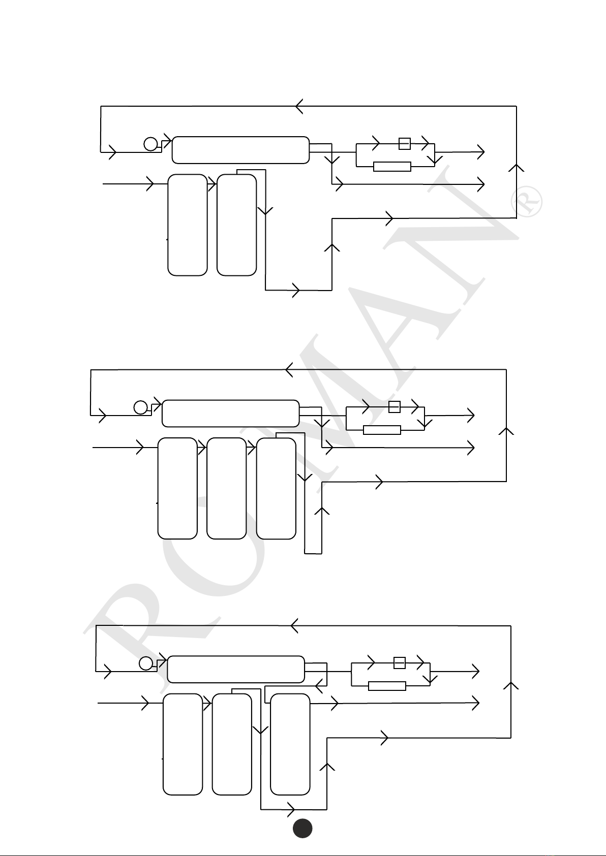
How Reverse Osmosis Works
Reverse Osmosis (RO) is one of the most convenient and effective filtration methods available. Reverse
Osmosis membranes can usually remove between 96% and 99% of most contaminants, including salts and
minerals, dyes, particles, bacteria and hazardous metals.
Simply put it is the process of osmosis backwards. Osmosis is the passage of water through a protein
membrane to equalize the concentration of particles dissolved in the water. The membrane allows water to
pass through however larger molecules like minerals, salts and bacteria cannot. In osmosis, water flows
back and forth until the concentration is equal on both sides of the membrane. By using pressure, the water
is forced to move away from the membrane rather than attempting to form an equilibrium like normal. This
against-flow motion is where the “reverse” in Reverse Osmosis comes from.
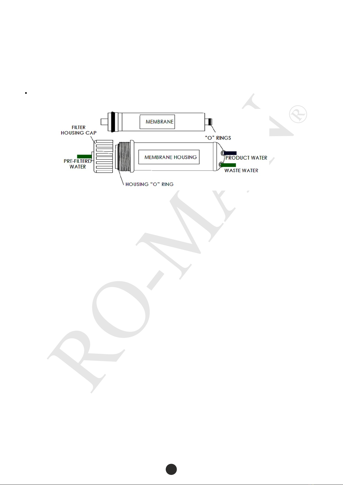
In Reverse Osmosis, the process works by separating contaminants from water by forcing the water
through a semi-permeable membrane. This membrane acts as a physical barrier to almost all molecules
with a molecular weight greater than 200 grams/mole. This membrane is rated at 0.0001 micron which
equals to 0.00000004 inch. For example, the membrane may allow passage of water molecules, but blocks
molecules of dissolved salt. Unwanted molecules are retained by the membrane while the ultra-pure water
continues on for use or further treatment. This is the same technology used to make bottled water and is
the only technology capable of desalinating sea water to be made into drinking water.
Non-RO water filters are much less effective with a larger pore size on these filter media, normally
between 0.5 – 10 micron. They can only filter out coarse particles, sediments and elements up to their
micron rating. Anything finer, as well as most dissolved substances, cannot be filtered out. As a result
water is a lot less clean and safe compared to reverse osmosis filtration.