RoamAlert AR3KY01-030 User manual

Access Keypad
Installation Guide
Access Keypad
Installation Guide

2
Access Keypad Installation Guide
Warranty
Stanley Healthcare Solutions' products are warranted against defects in materials and
workmanship and shall perform in accordance with published specifications for 1 year.
Stanley Healthcare Solutions' warranty is limited solely to the repair or replacement of
the defective part or product. Stanley Healthcare Solutions reserves the right to change
product specifications without notice.
Regulatory Statements
United States - Federal Communication Commission (FCC)
This device complies with Part 15 of the FCC Rules. Operation is subject to the follow-
ing two conditions: (1) this device may not cause harmful interference, and (2) this
device must accept any interference received, including interference that may cause unde-
sired operation.
NOTE: This equipment has been tested and found to comply with the limits for a Class
A digital device, pursuant to Part 15 of the FCC Rules. These limits are designed to pro-
vide reasonable protection against harmful interference when the equipment is operated
in a commercial environment. This equipment generates, uses and can radiate radio fre-
quency energy and, if not installed and used in accordance with the instruction manual,
may cause harmful interference to radio communications. Operation of this equipment
in a residential area is likely to cause harmful interference in which case the user will be
required to correct the interference at his own expense.
Warning: Any changes or modifications not expressly approved by Stanley Healthcare
Solutions could void the user's authority to operate the equipment.
Canada - Industry Canada
The term "IC:" before the certification/registration number only signifies that Industry
Canada technical specifications were met.
Important Recommendation
Stanley Healthcare Solutions’ systems are designed to assist staff in providing a high
degree of safety for people and assets and therefore should be used as a component of a
comprehensive security program of policies, procedures, and processes. As with every
security system, Stanley Healthcare Solutions highly recommends regular system opera-
tional checks to verify functional integrity.

3
Access Keypad Installation Guide
Introduction
Included in this Package
Access Keypad Overview
The access keypad is used by facility staff to temporarily bypass a protected exit, allowing
a tag to enter the exciter field without generating an alarm. The keypad also produces
audible and visual indication of alarm and bypass conditions and visual indication of
power on.
When the door controller is placed in test mode (Position 0, SW102), the keypad can be
used to help tune the exciter field. See “Door Controller and Exciter Installation Proce-
dure” in Chapter 4 of either the Halo Installation Manual (981-000026-000) or
the RoamAlert Installation Manual (981-000043-000) for details.
Two installation modes are available (set by JP3 on the back of the keypad):
• Mode 1 (formerly known as PINpad mode).
Up to 1000 unique PIN (Personal Identification Number) codes can be stored in the
door controller and managed at the RoamAlert server PC. In this mode, the Access
Keypad software tracks each code in the Activity Log. Use this mode when the facility
requires a record of which staff member bypassed the exit at a specific date and time.
• Mode 2 (formerly DKY Keypad mode).
This mode uses four generic passcodes, 2 for bypass and 2 for reset. Mode 2 is much
easier for the facility to administer, but it does not provide the detailed tracking and
added security of Mode 1. In Mode 2, only the date and time of each bypass is
recorded in the Activity Log.
QTY PART # Description
1 AR3KY01-030 Access Keypad
1N/A Keypad Cable
1N/A Modular Splitter (for two keypad installations)
1N/A Low voltage retrofit bracket
2N/A Mounting screws
1 981-000018-000 This document

4
Access Keypad Installation Guide
Specifications
Installation Tips
• Select the appropriate mode for this installation.
Identify whether the facility requires unique PIN codes or not.
• Select the appropriate volume level for audible alarm indication.
Is the keypad located in an area that must be kept quiet? The keypad has 5 volume
levels plus inaudible (off). Select the level according to facility requirements.
• Decide whether the keypad should initiate bypass prior to or after tag
detection.
Mount the keypad outside the exciter field to allow bypass before tag detection.
• Use the Y adapter for dual keypad installations.
If the exit requires two keypads (one on each side of the door), use the supplied Y
splitter to connect both keypads to the jack on the front of the controller.
Installation Procedure
Follow these steps to install the keypad:
1 Place the jumper on the upper 2 pins of JP3 on the keypad back to select
Mode 1 (unique PIN codes) or place the jumper on the lower two pins to
select Mode 2 (generic codes). If this is to be a Mode 2 keypad, continue
with “Mode 2 Passcode Programming Procedure” on page 5 after
completing keypad installation. See Figure 1 on page 7.
2 Set the appropriate volume level on J1 on the keypad back. Place the jumper
on the top pair of pins to set the volume to inaudible (off). Each lower pair
of pins increases the volume, with the bottom pair being the loudest. See
Figure 1 on page 7.
3 Mount a standard single-gang electrical box (not supplied), or the supplied
low-voltage retrofit bracket, at a convenient height (usually wall switch
height) in the selected location (usually just outside the exciter field). Careful
Input Rating 12 VDC @ 200 mA
Operating/Storage Temp 32° F to 120° F (0° C to 49° C)
Relative Humidity 0-85% RH @ 70° F (21° C) non-condensing
Dimensions 4.5” L x 2.75” W x 2.5” H (11.5 x 7.0 x 6.5 cm)
Mounting B11R Carlon Retrofit box (supplied)

5
Access Keypad Installation Guide
placement (not crooked) of all exposed components is the hallmark of a
professional installation.
4 Run the supplied keypad cable from the KEYPAD jack on the controller
front panel into the electrical box and connect to the keypad jack.
5 Mount the keypad into the electrical box or into the retrofit bracket with the
supplied screws.
Mode 2 Passcode Programming Procedure
When the keypad is in Mode 2, five memory slots on the keypad are available for pro-
gramming. Slots 1 and 3 are used for Bypass codes. Slots 2 and 4 are used for Reset codes.
A fifth slot is used for the Master Pass Code. The default codes assigned to the keypad
memory slots are:
• Bypass: 1938
• Reset: 1939
•Master: 987654
When you program the codes, you may use one code for both bypass slots and one code
for both Reset slots, but you cannot use the same code for Bypass and Reset. Usually, you
program separate codes and provide them to separate user groups.
To c h a n g e t he d e f a u l t Bypass or Reset codes, follow these steps:
1 Make sure the keypad has power.
2 Enter the Master Pass Code.
3 Press #.
4 Enter the slot number (1 or 3 for Bypass, 2 or 4 for Reset).
5 Press #.
6 Enter a new passcode (3 to 6 digits).
7 Press #.
8 Note the new passcode(s) and store in a safe place.
To c h a n g e t he d e f a u l t Master Pass Code, follow these steps:
1 Make sure the keypad has power.
2 Enter the Master Pass Code.
3 Press #.
4 Enter the Master Pass Code again.

6
Access Keypad Installation Guide
5 Press #.
6 Enter a new passcode (3 to 6 digits).
7 Press #.
8 Note the new Master Pass Code and store in a safe place.
To restore a factory default code, follow these steps:
1 Make sure the keypad has power.
2 Enter the Master Pass Code.
3 Press #.
4 Enter the slot number (1 or 3 for Bypass, 2 or 4 for Reset).
5 Press #.
6 Do NOT enter a passcode.
7 Press #again.
8 The default passcode is restored.
Master Reset
To reset the keypad to its factory default passcodes, follow these steps:
1 Apply power to the keypad.
2 Short the contacts on the J7 solder points at the upper right of the keypad
back. (See Figure 1 on page 7.) The keypad will beep.
3 Press the * key three times. The keypad will beep to indicate that the defaults
are loaded.
7
Access Keypad Installation Guide
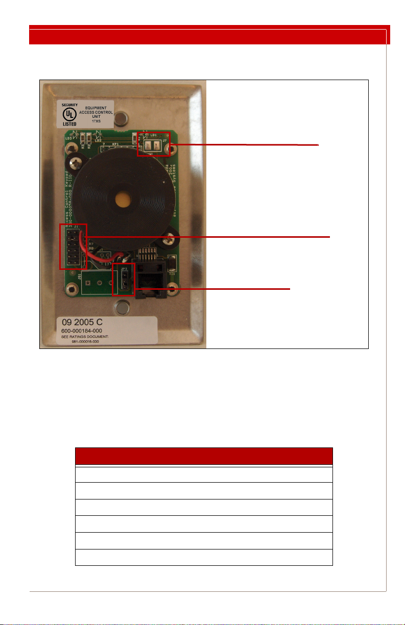
Access Keypad Notes and Diagrams
Figure 1: Keypad Jumper Locations
Connecting a Third-Party Keypad to a Controller
Third-party keypads can be connected to a Halo or RoamAlert R3 controller using a
6P6C modular plug according to the following pin-outs at the controller keypad jack,
from left (pin 1) to right (pin 6):
Pin Description
1+12V DC
2Ground
3BYPASS_IN
4RESET_IN
5ALARM_OUT
6BYPASS_OUT
J1 – Speaker Volume
Top Pair = OFF
Bottom Pair = Loudest
JP3 – Mode
Top Two = Mode 1
Bottom Two = Mode 2
J7 – Master Reset

Stanley Security Solutions
Senior Technologies Division
1550 N. 20th Circle
Lincoln, NE 68503
Telephone: USA: 800-824-2996
Canada: 866-559-6275
Int’l: +1 (613) 592-6997
Web site: www.stanleyhealthcare.com
© 2009 XMARK Corporation. All Rights Reserved.
August 2009. 981-000018-000 Rev 03.
Table of contents
Other RoamAlert Keypad manuals

Popular Keypad manuals by other brands


Lutron Electronics
Lutron Electronics seeTouch QS Application note

NWA Gates
NWA Gates KP-1050 user manual

AMX
AMX Metreau MET-13 installation guide

LEGRAND
LEGRAND AU7050 installation instructions

Lutron Electronics
Lutron Electronics HOMEWORKS HRT-6LRL installation instructions

Rockwell Automation
Rockwell Automation Allen-Bradley RediPANEL 2705 user manual