ROBBE Multi-Switch Prop 12+2 18370 User manual
No.
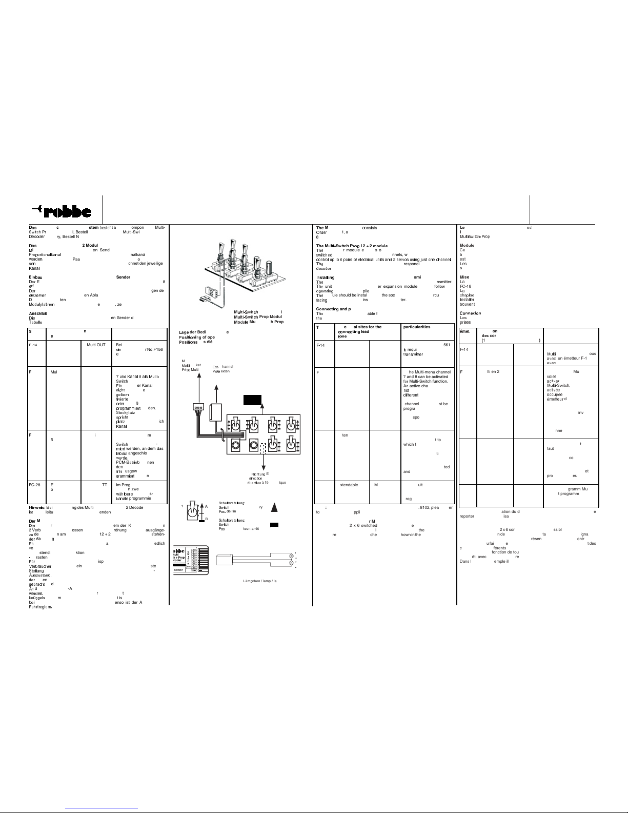
Multi-Switch Prop 12 + 2 Modul / Multi-Switch Prop12 + 2 Decoder Memory
Bedienungsanleitung Operating instructions Notice d'utilisation
8101, 8370
L
/ lamp / lampe
M
Prop Modul
Prop Modul
Multi-switch Prop
!
"
#
der Bedienelemente
P
$
%
&
'
&
$
(
&
(
)
of operating elements
*
+
,
-
.
-
+
/
,
des éléments d'opération
E
0
1
2
Channel
V
3
4
5
extensible
6
ulti-Buchse
7
8
9
:
;
socket
<
=
>
?
@
Multi
R
A
B
C
D
F
G
H
Elektronik
d
I
J
K
N
O
I
Q
S
of electronics
T
U
W
X
Y
Z
U
[
\
à l'électronique
]
^
_
`
a b c
e
f
g
h
Multi-Switch Prop 12 + 2 System
i
j
k
l
j
m
l
aus den Komponenten Multi-
n
o
p
q
r
s
Prop 12+2 Modul, Bestell Nr. 8101 und dem Multi-Switch Prop 12+2
t
u
v
w
x
u
y
Memory, Bestell Nr. 8370.
z
{
|
Multi-Switch Prop 12 + 2 Modul
}
it diesem Modul, welches in den Sender eingebaut wird, kann ein
~
auf 2 x 6 Schaltkanäle und 2 Proportionalkanäle erweitert
so daß bis zu 6 Paare von Verbrauchern und 2 Servos angeschlos-
werden können. Die aufgedruckte Nummer kennzeichnet den jeweiligen
am Decoder-Ausgang.
des Multi-Switch Prop Moduls in den Sender
Einbau kann in die Sender der Serien F-14, FC-16, FC-18 und FC-28
rfolgen.
¡
mechanische Einbau entspricht dem in den Bedienungsanleitungen der
¢
£
¤
¥
¢
¦
¤
¢
¤
Sender beschriebenen Ablauf bei den Ausbau-Optionen.
§
ie Module sollten so eingebaut werden, daß die Buchsen auf den
¨
©
ª
«
¬
¬
®
¯
°
±
²
±
nach unten, zum Senderinneren, zeigen.
³
´
µ
¶
·
¸
¹
º
und Programmierung
»
¼
½
richtigen Anschlüsse sind für den jeweiligen Sender der nachfolgenden
¾
¿
À
Á
Â
Â
Á
zu entnehmen.
Ã
ender Steckplätze für Anschlußkabel Besonderheiten
Ä
in-adrig 3-adrig
Å
Æ
Ç
È
Multi IN 1-3 Multi OUT Bei F-14 mit 7 Kanälen ist
É
Ê
Ë
Multi-Adapter No.F1561
Ì
rforderlich.
Í
C-16 Multi in 2/1 to Multi OP Im Menü Multi kann Kanal
Î
Ï
Ð
Ñ
Ò
Ó
Ð
Ó
Ô
Õ
Ó
Ô
Ö
×
Ï
Ô
Ø
Ù
Ú
Û
Ü
Ý
Þ
ß
à
aktiviert werden.
á
â
ã
aktivierter Kanal darf
ä
å
æ
ç
è
mit anderen Steuer
é
ê
ë
ê
ì
í
belegt sein. Der ak-
î
ï
ð
ï
ñ
ò
î
ñ
Multi-Kanal (Kanal 7
ó
ô
õ
ö
8) muß auf „reverse“
÷
ø
ù
ú
ø
û
ü
ü
ý
þ
ø
ÿ
werden. Der
S
„MULTI-IN 1 ent-
s
Kanal 8, der Steck
p
MULTI-IN 2 entspricht
K
7
F
C-18 Ext. Channel Multi Im Menü MULTI, muß der
5
...8 Steckanschluß als Multi-
Kanal program-
m
werden, an dem das
M
!
"
angeschlossen
w
#
$
%
&
'
Im PPM- und
P
(
)
*
+
,
-
.
/
,
0
können aus
d
1
2
Kanälen 5...8 zwei
f
3
4
6
ausgewählt und pro-
g
7
8
9
9
:
;
7
<
werden
=
C-28 Ext. Channel Multi BATT Im Programm MULTI
>
...8 müssen zwei beliebig
?
@
A
B
C
D
E
G
Funktions-
k
H
I
J
L
N
programmiert
O
Q
R
T
U
Q
V
W
X
Y
Z
Verwendung des Multi-Switch Prop 12 + 2 Decoders, No. 8102
i
[
\
die Anleitung des Decoders zu verwenden.
]
^
_
Multi-Switch Prop 12 + 2 Decoder Memory
`
a
b
Decoder hat 2 x 6 Schaltausgänge. An jedem der Kanäle 1 - 6 können
c
Verbraucher angeschlossen werden. Die Zuordnung der Schaltausgänge-
z
e
den Schaltern am Multi-Switch Prop 12 + 2 Modul geht aus nebenstehen-
h
j
l
Abbildung hervor
n
o
ist zu beachten, daß sich rastende und tastende Schalter unterschiedlich
v
erhalten.
q
tastend: reine Tastfunktion
r
rastend: mit Speicherfunktion
t
u
x
das nebenstehend abgebildete Beispiel bedeutet das folgendes:
y
{
|
}
|
~
{
|
A ist solange eingeschaltet, wie der Schalter 1 in der tastenden
gehalten wird. Verbraucher B speichert den aktuellen Ein- bzw.
eine Zustandsänderung entsteht dadurch, daß der Schalter aus
rastenden Stellung B in Mittelstellung und dananch wieder in Stellung B
wird.
den 2 Proportional-Ausgängen 7 und 8 können 2 Servos angeschlossen
¡
¢
£
¤
Die Servo-Ausschläge entsprechen dem Steuerweg eines Steuer-
¥
¦
§
¨
¨
©
ª
«
mit Trimmung. Die Stellgeschwindigkeit ist etwas langsamer, was
¬
®
Sonderfunktionen meist erwünscht ist. Ebenso ist der Anschluß von
¯
°
±
²
³
²
´
µ
¶
´
²
·
¸
Schaltern etc. möglich.
¹
º
»
¼
½
¾
¿
À
Á
¾
¿
½
½
Â
Ã
Ä
Å
tastend
Æ
Ç
È
É
Ê
Ë
position: momentary
Ì
Í
Î
Ï
de l'interrupteur: contact
Ð
Ñ
Ò
Ó
Ô
Õ
Ö
×
Ø
Õ
Ö
Ô
Ô
Ù
Ú
Û
Ü
rastend
Ý
Þ
ß
à
á
â
position: latching
ã
ä
å
del'interrupteur: arrêt
æ
ç
è
Multi-Prop system
é
ê
ë
ì
í
ì
î
ì
of the Multi-Switch Prop 12 + 2 module,
ï
ð
ñ
ò
ð
No. 8101, and the Multi-Switch Prop 12+2 decoder memory, Order No.
ó
370.
ô
õ
ö
÷
ø
ù
ú
û
ü
ý
þ
û
ú
ÿ
õ
T
ø
ù
ö
transmitter module expands one proportional channel to give 2 x 6
s
channels and 2 proportional channels, which means that you can
c
c
c
!
"
#
c
$
%
&
'
(
numbers printed on the module mark the corresponding channels at the
d
)
*
+
d
)
,
output.
I
-
.
/
0
1
1
2
-
3
the Multi-Switch Prop module in the transmitter
4
5
6
module can be fitted in an F-14, FC-16, FC-18 or FC-28 series transmitter.
7
8
9
unit is installed like any other expansion module; please follow the
o
:
;
<
=
>
?
@
A
instructions supplied with your transmitter.
B
C
D
module should be installed with the sockets on the module circuit board
f
E
F
G
H
J
down, towards the inside of the transmitter.
K
L
M
M
N
O
P
Q
M
R
and programming
S
U
V
correct connections suitable for the respective transmitter are shown in
t
W
X
table below.
Y
ransm. receptical sites for the particularities
Z
[
\
\
]
Z
^
_
\
`
leads
a
b
e
g
wire) (three wires)
h
i
j
k
Multi IN 1- 3 Multi OUT A Multi-adapter No.F1561
l
m
required for the F-14
n
p
q
r
u
v
w
n
n
x
p
with 7 channels.
y
C-16 Multi in 2/1 to Multi OP In the Multi-menu channel
z
and 8 can be activated
{
|
}
Multi-Switch function.
~
active channel may
be seized by a
control transm.
the activated multi-channel
(channel 7 or 8) must be
programmed to „reverse“.
the „MULTI-IN 1“ socket
corresponds to channel 8,
the „MULTI-IN 2 socket
corresponds to channel 7.
FC-18 extendable Multi In the Multi-menu the
channel 5...8 connection socket to
which the module was
connected has to be
programed as Multi-switch
channel. For PPM and
PCM operation any two
channels can be selected
and programmed among
the channels 5...8.
FC-28 extendable Multi BATT In the Multi-program any
channel 5...8 two selectable function
channels must be
programmed.
Note: if you are using the Multi-Switch 12 + 2 Decoder, No. 8102, please refer
to the instructions supplied with that decoder.
Multi-Switch 12 + 2 Decoder Memory
The decoder has 2 x 6 switched outputs, and two electrical units can be
connected to each of the channels 1 - 6. The switches on the Multi-Switch 16
module are assigned to be switched outputs as shown in the illustration shown
here.
Note that the latching and momentary switches are different in operation.
- momentary: pure momentary switch function.
- latching: with memory function.
The example in the illustration makes this clear:
Unit A remains switched on for as long as the switch 1 is held in the „ON“
position. Unit B, on the other hand, stores the current ON or OFF state, and
ist state only changes when the switch is moved from the latched position B
to centre, and then to position B again.
Two servos can be connected to the proportional outputs 7 and 8. The servo
movement is proportional to the stick position, and includes trim travel. Servo
transit speed is slightly reduced, but this is usually desirable with auxiliary
working systems in any case.
système Multiswitch-Prop 12 + 2
constitué des composants suivants:
e module Multiswitch-Prop 12+2, réf. 8101 et le décodeur memory
12+2, réf. 8370.
¡
¢
£
Multiswitch-Prop 12 + 2
¤
¥
module qui s’intègre à l’émetteur permet de porter une voie proportionnelle
à
2 x 6 voies de commutation plus deux voies proportionnelles de sorte qu’il
¦
§
¨
possible d’y raccorder 6 paires d’utilisateurs tout-ou-rien et 2 servos.
©
ª
«
numéros repérés correspondent au canal respectif à la sortie du décodeur
¬
olidaire.
®
¯
°
en place du module Multiswitch Prop dans l’émetteur
±
²
mise en place peut intervenir dans des émetteurs des séries F-14, FC-16,
³
´
µ
¶
·
et FC-28.
¸
¹
mise en place mécanique est décrite dans le manuel de l’émetteur au
º
»
¼
½
¾
¿
À
Á
des extensions.
Â
Ã
Ä
Å
Æ
Ç
Ç
È
É
les modules de telle sorte que les douilles sur la platine du module se
Ê
Ë
Ì
Í
Î
Ï
Ð
Ê
en bas, vers l’intérieur de l’émetteur.
Ñ
Ò
Ó
Ó
Ô
Õ
Ö
Ò
Ó
et programmation
×
Ø
Ù
possibilités de connexion approprié pour l’émetteur respectif peuvent être
Ú
Û
Ü
Ý
Þ
Ý
dans la table suivante.
é
ß
á
â
ã
position des prises pour particularités
ä
å
æ
cordons de connexion
ç
è
cordon) (3 cordons)
ê
ë
ì
í
Multi IN 1 à 3 Multi OUT Il faut avoir un adapteur
î
ï
ð
ñ
ò
réf. F1561 quand vous
ó
ô
õ
ö
un émetteur F-14
÷
ø
ù
ú
7 voies.
û
C-16 Multi en 2/1 à Multi OP Dans le menu Multi les
ü
ý
þ
ÿ
v
7 et 8 peuvent etre
a
pour la fonction
M
Une voie
ne doit pas être
o
par un autre
é
de commande.
la voie multiple activée (voie
7 ou 8) doit être
programmée sur inversion
(reverse).
Le connecteur „MULTI-IN
1“ correspond à la voie 8 et
le connecteur „MULTI-IN 2“
à la voie 7.
FC-18 Voie extensible Multi Dans le menu Multi il
5...8. faut que le connecteur
connecté au module soit
programmé comme une
voie Multi-Switch. Lors
de l’opération PPM et
PCM on peut choisir et
programmer deux des
voies 5...8.
FC-28 Voie extensible Multi BATT Dans le programm Multi
5...8. on doit programmer deux
voies de fonction
n’import quelles.
A noter: en cas d’utilisation du décodeur Multi-Switch 12 + 2, réf. 8102, se
reporter à la notice d’utilisation du décodeur.
Mémoire du décodeur Multi-Switch 12 + 2
Le décodeur présente 2 x 6 sorties de signal. Il est possible de brancher deux
utilisateurs sur chacun des canaux 1-6. L’affectation des sorties de signal aux
interrupteurs du Multi-Switch 16 est représentée sur la figure ci-contre.
Tenir compte du fait qu’interrupteurs à arrêt et interrupteurs à contact ont des
comportements différents.
- contact: pure fonction de touche
- arrêt: avec fonction mémoire
Dans le cas de l’exemple illustré ci-contre, cela signifique que:
l’utilisateur A est en circuit tant que l’interrupteur 1 est maintenu en position
de contact. L’utilisateur B enregistre l’état d’entree ou de sortie actuel, une
modification d’état intervient lorsque l’interrupteur est amené de la position
d’arrêt B en position intermédaire et ensuite ramené dans la position B.
Aux sorties proportionnelles 7 et 8 il est possible de raccorder chaque fois un
servo. Le débattement des servos correspond à la course d’un manche avec
trim. La vitesse est légèrement inférieure ce qui est souvent souhaité pour les
fonctions secondaires. Il est également possible d’y raccorder des variateurs,
de commutateurs etc.
1
4 3 2 1
86 57

No.
Multi-Switch Prop 12 + 2 Modul / Multi-Switch Prop12 + 2 Decoder Memory
Bedienungsanleitung Operating instructions Notice d'utilisation
8101, 8370
w
!
"
#
$
w
%
"
&
!
$
'
(
)
*
+
,
-
.
-
r
/
0
/ red / rouge = "+"
s
2
3
4
5
6
7
/ black / noir = "-"
P
8
9
:
P
P
9
;
<
=
>
?
@
A
B
C
D
E
F
CM/PPM-switch
G
CM/PPM-commutateur
H
I
J
K
L
N
O
Q
R
S
T
J
U
T
S
N
S
für Multi-Switch-Funktionen
V
xample of connecting the Multi-switch funktions
W
es examples pour connecter les fonctions Multi-switch
X
1439
Y
404
Z
rahtbrücken
[
\
]
^
links
_
hunts
`
b
c
d
e
f
g
h
i
j
k
h
l
k
m
j
e
n
über Relais-Modul
p
q
t
u
x
y
z
feature for relais-module
{
|
|
}
~
}
suppliémentaire pour module des relais
leinmotor / small-size motor / petit moteur électrique
/ Sound-module,
/ lamp / lampe
Relais-Modul
Akku
nschluß
nach Anschluß und Programmierung muß der Decoder an den
¡
¢
£
¤
¥
¦
§
¨
©
¤
©
ª
angeschlossen werden, der im Sender mit dem MS 12+2
«
¬
®
¯
belegt wurde.
°
±
²
dem PCM / PPM Umschalter die Übertragungsart einstellen. Die Position
³
´
µ
¶
µ
¶
Schalters muß dem verwendeten Empfänger entsprechen.
·
¸
¹
º
vorn: PPM-Empfänger
»
¼
½
¾
hinten: PCM-Empfänger
¿
À
Á
Â
Ã
Ä
Å
Å
Æ
Á
Ç
È
É
Ê
Ë
Á
Â
Ì
Í
Å
Æ
Î
Ï
¿
À
Á
Â
Ì
Í
Ð
Å
Ã
Ä
Á
Ñ
Ä
Ê
Ò
Ó
Ô
Õ
Ð
Ã
Ã
Ä
Ê
À
Ä
È
É
Ê
Á
Ä
Í
Ö
Ä
Á
×
Ø
Ù
Ú
Versorgung der Verbraucher muß ein Akku (4,8 - 24 V) an die Buchse
Û
BATT“angeschlossen werden. Als Anschlußkabel dafür eignet sich das
Ü
Ý
Þ
Þ
ß
à
á
ß
â
ã
ä
å
æ
ç
è
ê
ë
ì
Ý
í
ß
è
î
Bestell Nr. 4404. (rot = +, schwarz = -). Zwischen
ï
ð
ñ
ï
ò
ó
ï
ò
Stromquelle und Decoder (Anschluß „BATT“) empfiehlt sich der
ô
õ
ö
÷
ø
ù
eines Trennschalters.
ú
û
ü
Anschluß der Verbraucher an die Schaltausgänge 1 - 6 empfehlen wir die
ý
þ
ÿ
S
þ
Bestell Nr. F 1439.
P
Kanal kann ein Paar von Verbrauchern gemäß Skizze angeschlossen
w
erden:
B
Verbraucher sind also über die rote Anschlußleitung gemeinsam mit
d
Pluspol der Batterie verbunden. Über die weiße oder schwarze Leitung
der Verbraucher auf Masse (Akkuminus) geschaltet.
D
beiden Servos der Kanäle 7 und 8 werden aus dem Empfängerakku
v
sind also von der Verbraucherstromquelle unabhängig.
icherheitshinweise
-
Den Versorgungsakku für die Verbraucher nur an die Buchse „BATT“
a
nschließen.
Die Schaltausgänge nicht kurzschließen bzw. keine externe Spannung
e
inspeisen.
Keine Servos an den Schaltausgängen 1 - 6 anschließen. Dies führt zur
Z
!
"
#
$
der Servos.
%
Die angegebenen Grenzwerte für Strom und Spannung nicht überschrei-
t
en.
T
&
'
(
)
*
+
'
(
&
Daten
,
Dauerstrom pro Ausgang: 1,8 A, ein Ausgang aktiv
1
A, 4 Ausgänge aktiv
0
.
/
A alle 6 Ausgänge aktiv
2
3
4
5
3
6
7
8
9
:
;
<
=
5
>
<
?
@
A
?
7
:
C
E
F
G
H
I
J
K
L
M
J
N
O
Q
R
U
Ausgänge 5 (*) und 6 (*) sind mit dem 1,5-2 fachen des
V
W
X
Y
[
\
der Ausgänge 1-4 belastbar. Für Verbraucher mit hohen Last-
s
]
^
_
`
b
c
daher die Ausgänge 5 und 6 verwenden.
f
g
h
Gesamt-Dauerstrom darf 5 A - 6 A nicht überschreiten Größere
i
j
k
l
k
l
m
n
o
p
können über ein Relais -Modul No. 8303 oder ein Relais-
q
r
u
x
y
r
x
z
{
y
No. 8304 geschaltet werden.
|
Versorgungsspannung: „BATT“4,8 - 24 V
}
Rx“4,8 - 6 V
~
Ruhestromaufnahme (Rx): ca. 50 mA
Strombegrenzung:
A - 6 A je Ausgang (temperaturabh.) als Schutz gegen Überlastung
Kurzschluß
Schutz der Ausgänge gegen thermische Überlastung
Abmessungen (Decoder): 62 x 32 x 24 mm
Gewicht (Decoder): ca. 30 g
der Platine des Decoders befinden sich die beiden Draht-
„A“und „B“.
: geschlossen für System robbe Futaba
für Fremdfabrikat Graupner Nautic-Expert
¡
¢
geschlossen für Normalbetrieb (Memory Funktion für rastende Schalter-
£
tellungen). Durch Öffnen der Brücke wird die Memory Funktion
¤
¥
¦
§
¨
©
ª
©
¥
«
¨
¬
Rastende und tastende Schalterstellungen sind dann gleich-
®
¯
°
±
²
³
Die Speicherwirkung entfällt.
´
µ
¶
Drahtbrücken können nach Trennen der Versorgungsspannung und
·
¸
¹
º
»
¼
º
¹
des Gehäuses mit einem kleinen Seitenschneider vorsichtig
½
¾
¿
À
À
Á
¾
Â
werden. Schließen durch Zusammenlöten der Drähte.
Ã
Ä
Å
Æ
Ç
È
Å
É
É
Å
Störungen können mit einem Entstörfilter No. F 1413 zwischen
Ê
Ë
Ì
Í
Î
Ï
Ð
Ñ
Ò
und Decoder wirkungsvoll unterdrückt werden.
Ó
Ô
Õ
Relais-Modul in Verbindung mit dem Multi-Switch Prop MS 12 + 2
Ö
×
Ø
SchaltrichtungdesRelais-Moduls ist durchdasweißeKabelvorgegeben.
Ù
Ú
Û
Modul schaltet, wenn der Schalter nach vorn betätigt wird. Wird die
Ü
Ý
Þ
ß
Ü
ß
Ü
Ý
ß
Ü
à
Ü
Þ
á
Þ
Ü
Schaltrichtung gewünscht, das weiße Kabel nach Lösen
â
ã
ä
Lasche herausziehen und auf den freien Platz umstecken.
å
æ
ç
è
é
ê
ë
ì
í
î
ï
ç
í
ï
ð
ñ
ç
in Verbindung mit dem Multi-Switch MS Prop 12+2
ò
ó
das Relais-Umpolmodul an den Decodern zu betreiben, ist das V-Kabel,
ô
õ
ö
F 1423 erforderlich. Aus einem der beiden Stecker das weiße Kabel nach
÷
ø
ù
ú
û
der Lasche herausziehen und auf den freien Steckplatz des zweiten
ü
ý
þ
ÿ
S
þ
einrasten lassen. Beide Stecker am V-Kabel anschließen. V-Kabel
a
gewünschten Kanal des Decoders anschließen. Bei Verwendung eines
r
Schalters ist die Memory-Funktion des Decoders zu deaktivieren.
8
304
303
F
1423
K 7 / K 8
!
"
V
#
$
%
&
servo K 7 / K 8
Connections
Note: the decoder must be connected to the receiver channel corresponding
to the channel occupied by the Multi-Switch Prop 12+2 module in the
transmitter. This will vary from one application to another.
The PCM/PPM change-over switch is used to set the correct transmission
mode. The position of this switch must correspond to the receiver you are
using:
forward: PPM receiver
back: PCM receiver
Be sure to make this adjustment before you connect the receiver battery and
switch the system on.
A separate battery is required to power the electrical units. The voltage of this
battery should be 4.8 - 24 V, and it must be connected to the socket marked
„BATT“.. Use the battery cable, Order No. 4404, for this connection (red = +,
black = -). We recommend that you fit an isolation switch between the external
battery and the decoder („BATT“socket).
We recommend servo cables, Order No. F 1439, for connecting the electrical
units to the switched outputs 1 - 6.
A pair of electrical units can be connected to each channel as shown in the
diagram:
Connect both units to the positive battery terminal using a common red wire.
Connect the unit to earth (battery negative) with the white or black wire.
The two servos connected to channels 7 and 8 are powered by the receiver
battery, i.e. they are independent of the auxiliary battery.
Safety notes
- Be sure to connect the battery for the electrical units to the socket marked
„BATT“only.
- Avoid short circuits at the decoder outputs , and do not apply a voltage to
the sockets.
- Do not connect servos to the switched outputs 1 - 6, as this will ruin the
servos.
- Do not exceed the limit values for current and voltage.
Specification
* Continuous current per output: 1.8 A, one output active
1 A, 4 outputs active
0.8 A, all 6 outputs active
0.5 A, more than 8 outputs active
* Note: outputs 5 (*) and 6 (*) can tolerate 1.5 - 2 times the current of outputs
1 - 4. For this reason you should use outputs 5 and 6 for electrical units
drawing high load currents.
The total continuous current should not exceed 5 - 6 A. If you need to
switch heavier load currents you can wire a relay module No. 8303, or a
relay reversing module, No 8304 into the circuit.
* Power supply: „BATT“4.8 - 24 V
„RX“4.8 - 6 V
* Idle current drain (Rx): approx. 50 mA
* Current limiting:
3 - 6 A per output (temperature-dependent), to guard against overload due
to short-circuit.
* All outputs are protected against thermal overload
* Dimensions (decoder): 62 x 32 x 24 mm
* Weight (decoder): approx. 30 g
Note: the circuit board of the decoder features two wire links „A“and „B“.
A: closed for Robbe Futaba system
open for Graupner Nautic-Expert system
B: normally closed (memory function for latching switch positions). You can
disable the memory function by disconnecting the bridge, in which case
all the switch positions are momentary in action, and the memory effect
is eliminated.
To open the wire links disconnect the power supply and open the case and cut
the wire carefully with a small pair of side-cutters. To close a link solder the
wires together again.
If you encounter radio interference fit a suppressor filter, No. F 1413, between
the receiver and decoder for an effective cure.
Relay module in conjunction with the MS 12 + 2 Multi-Switch Prop
systems
The direction of switching of the relay module is defined by the white wire. As
standard the module trips when the switch is moved forward. If you want the
relay to trip in the opposite direction, unlatch the plug contact, withdraw the
white wire and push it into the vacant position.
Relay reversing module in conjunction with the MS 12 + 2 Multi-Switch
Prop system
You will need an Y-lead, No. F 1423, to operate the relay reversing module
with the decoders. Unlatch the contact in one of the two plugs, withdraw the
white wire and push it into the vacant position in the second plug. Connect both
plugs to the Y-lead and connect the Y-lead to the channel you wish to use on
the decoder. If you use a latching switch it is necessary to disable the memory
function.
We reserve the right to alter technical specifications.
Connexion
À noter: en fonction de la connexion et de la programmation, il faut raccorder
le décodeur à la voie du récepteur correspondant à la voie de l’émetteur sur
laquelle a été branché le module MS 12+2.
Régler le mode de transmission avec le commutateur PCM / PPM. La position
de ce commutateur doit correspondre au récepteur utilisé:
vers l’avant: récepteur PPM
vers l’arrière: récepteur PCM.
Effectuer cet ajustement avant de raccorder/mettre en marche l’alimentation
du récepteur Rx.
Pour l’alimentation des utilisateurs, il faut un accu de 4,8 à 24 volts raccordé
à la douille „BATT“. Le cordon de connexion adapté pour l’alimentation porte
la réf. 4004 (rouge = +, noir = -). Entre la source d’alimentation externe et le
décodeur (raccord „BATT“) il est recommandé d’installer un commutateur/
séparateur.
Pour raccorder les utilisateurs aux sorties de commutation 1 à 6, utiliser un
cordon de servo, réf. F 1439.
Par voie, il est possible de raccorder deux utilisateurs, comme indiqué sur le
schéma:
les deux utilisateurs sont ainsi raccordés en commun par le brin rouge au pôle
positif de l’alimentation. Le brin blanc ou noir met l’utilisateur à la masse
(moins de l’accu).
Les deux sorties 7 et 8 sont alimentée par l’accu du récepteur et sont ainsi
autonomes par rapport à l’alimentation des utilisateurs.
Consignes de sécurité
- Raccorder l’accu d’alimentation des utilisateurs à la douille „BATT“.
- Ne pas mettre les sorties en court circuit ou sous tension externe.
- Ne pas raccorder de servos aux sorties de commutation 1 à 6. Ceci détruit
les servos.
- Ne pas dépasser les valeurs limites pour le courant et la tension.
Caractéristiques techniques
* Courant permanent par sortie: 1,8 A, une sortie active
1 A, 4 sorties actives
0,8 A, les 6 sorties actives
0, 5 A, plus de 8 sorties sollicités
* À noter: les sorties 5 (*) et 6 (*) peuvent subir un courant de 1,5 à 2 fois
supérieur aux sorties 1 à 4. Utiliser donc ces sorties 5 et 6 pour les
utilisateurs à hauts courants de charge. Le courant de charge permanent
ne doit pas dépasser 5 à 6 A. Il est possible de transmettre des courants
de charge plus important par l’intermédiaire d’un module-relais réf. 8303
ou d’un module-relais inverseur réf. 8304.
* Tension d’alimentation: „BATT“4,8 à 24 volts
„Rx“4,8 à 6 volts
* Consommation au repos (Rx): 50 mA environ
* Limitation du courant: 3 A à 6 A selon sortie (en fonction de
la température) protection contre les surcharges par court-circuit.
* Protection des sorties contre les surcharges thermiques
* encombrement, (décodeur): 62 x 32 x 24 mm
* poids, (décodeur): 30 g environ
À noter: sur la platine se trouvent les deux shunts „A“et „B“.
A: fermé pour le système robbe-Futaba,
ouvert pour le module Nautic-Expert de Graupner
B: fermépourlefonctionnementnormal(fonctionmémoirepourlespositions
de l’interrupteur avec arrêt). L’ouverture du pont désactive la fonction
mémoire. Les positions contact et arrêt des interrupteurs ont alors le
même effet. La fonction mémoire est hors service.
Il est possible d’ouvrir les shunts après avoir coupé l’alimentation et retiré le
boîtier, en procédant avec précaution, à l’aide d’une petite pince coupante.
Fermeture par soudure des brins. Il est possible de discriminer les
dérangements éventuels en installant un filtre antiparasite réf. F 1413 entre
le récepteur et le décodeur.
Module-relais raccordés aux systèmes Multiswitch MS Prop 12 + 2.
Le sens de commutation du module-relais est donné par le brin blanc. Le
module commute lorsque le commutateur est déplacé vers l’avant. Si vous
souhaitez obtenir la commutation dans l’autre direction, retirer le brin blanc
après avoir desseré l’éclisse et le planter dans l’emplacement libre.
Module-relais inverseur raccordés aux systèmes Multiswitch MS Prop
12 + 2.
Pour associer le module-relais inverseur au décodeur, il faut un cordon Y, réf.
F 1423. Retirer le brin blanc de l’un des emplacements après avoir desseré
l’éclisse et le planter dans l’un des emplacements libres du second
connecteur. Raccorder les deux connecteurs au cordon Y. Raccorder le
cordon Y à la voie souhaitée du décodeur. En utilisant un interrupteur avec
arrêt, c'est nécessaire de desactiver la fonction mémoire.
Sous réserve de modification technique.
RX
AvioTiger Germany GmbH - Theresienhöhe 28 - 80339 München Telefon: 089 / 215 466 470 - info@aviotiger-germany.de "robbe Modellsport" ist eingetragenes Markenzeichen der AvioTiger Germany GmbH.
Irrtum, Druckfehler und technische Änderungen vorbehalten. Copyright AvioTiger Germany 2015. Kopie und Nachdruck, auch auszugsweise, nur mit schriftlicher Genehmigung der AvioTiger Germany GmbH.
This manual suits for next models
1


