Clarion Addzest DVH920 User manual

Owner’s manual
Mode d’emploi
Manual de instrucciones
All Rights Reserved. Copyright © 2002: Clarion Co., Ltd.
Printed in Japan / Imprimé au Japon / Impreso en Japón / 在曰本印刷
2002/2 (A·K)
GP-978B
280-7805-00
Clarion Co., Ltd.
5.1CH SURROUND DECODER
•
DÉCODEUR SURROUND 5.1 CANAUX
•
DESCODIFICADOR DE 5.1CH SURROUND
•
5.1ch環繞聲解碼器
Contents
1. PRECAUTIONS ............................................................................................................................... 2
2. FEATURES ...................................................................................................................................... 3
3. SPECIFICATIONS ........................................................................................................................... 4
4. CONTROLS ..................................................................................................................................... 5
5. NOMENCLATURE........................................................................................................................... 5
Names of Buttons ............................................................................................................................ 5
Center Unit Display .......................................................................................................................... 6
6.CONFIRM BEFORE OPERATION .................................................................................................. 7
7. OPERATIONS ................................................................................................................................. 9
Operations (DXZ925) ...................................................................................................................... 9
Setting Acoustic Features (DXZ925) ............................................................................................. 10
8. WIRING TECHNIQUES ................................................................................................................. 13
Name of Parts ................................................................................................................................13
How to Wire This Unit .................................................................................................................... 14
9. INSTALLATION ............................................................................................................................. 15
Installation Precautions ................................................................................................................. 15
Installation Example ...................................................................................................................... 15
10. SYSTEM EXPANSION .................................................................................................................. 16
Example: VRX925VD + DVD Changer ......................................................................................... 16
Example: DXZ925 + DVD Changer + Monitor .............................................................................. 17
Example: DXZ825 + DVD Changer + Monitor .............................................................................. 18
11. IN CASE OF DIFFICULTY ............................................................................................................ 72
Thank you for purchasing the Clarion product.
* Please read this owner’s manual in its entirety before operating this equipment.
* After reading this manual, be sure to keep it in a handy place (e.g., glove compartment).
* Check the contents of the enclosed warranty card and keep it carefully with this manual.
* The DVH920 can be operated by the CeNET-compatible Clarion Center Units DXZ925 or VRX925VD.
These operating instructions note functions which change as the result of connecting the DVH920 to
one of the above components.
2DVH920
280-7805-00
DVH920 73
1. PRECAUTIONS
1. The DVH920 can easily be damaged by mois-
ture, high temperatures or high humidity. Keep
the inside of the car clean and well ventilated.
2. Never subject the DVH920 to strong shocks
or open its case. Doing so may result in dam-
age.
3. Use a soft, dry cloth to wipe dirt off the
DVH920. Never use a hard cloth or thinner,
alcohol, etc. For tough dirt, apply some cold
or lukewarm water to a soft cloth and wipe off
the dirt gently.
4. When the main unit is switched to the traffic
announcement or PTY interrupt reception
while using the DVH920, the effect from
DVH920 doesn’t work.
5. Some tracks may sound distored when ad-
justment; this is normal and not a cause for
concern.
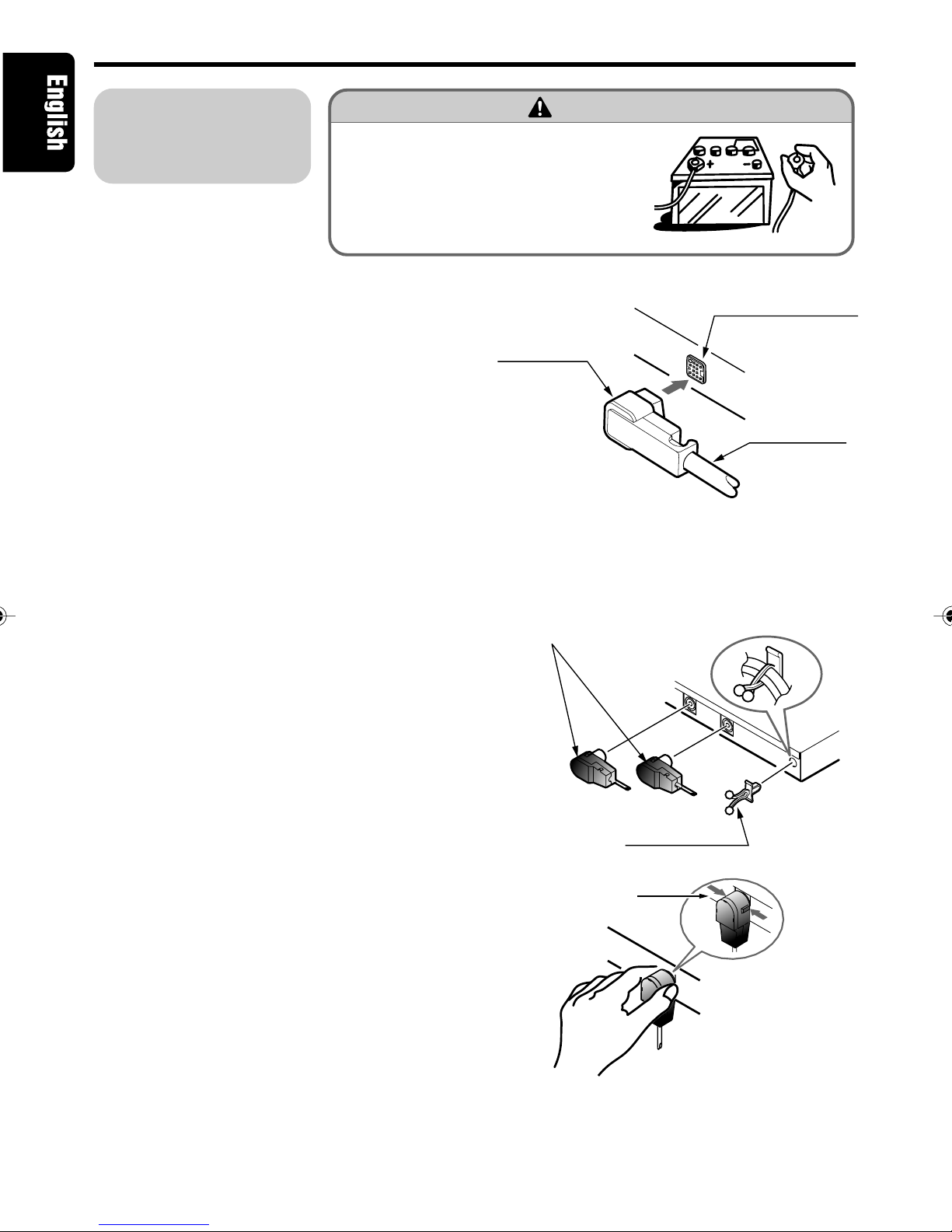
CAUTION
CHANGES OR MODIFICATIONS NOT EX-
PRESSLY APPROVED BY THE MANUFAC-
TURER FOR COMPLIANCE COULD VOID THE
USER’S AUTHORITY TO OPERATE THE
EQUIPMENT.
INFORMATION FOR USERS:
CHANGES OR MODIFICATIONS TO THIS
PRODUCT NOT APPROVED BY THE MANU-
FACTURER WILL VOID THE WARRANTY.
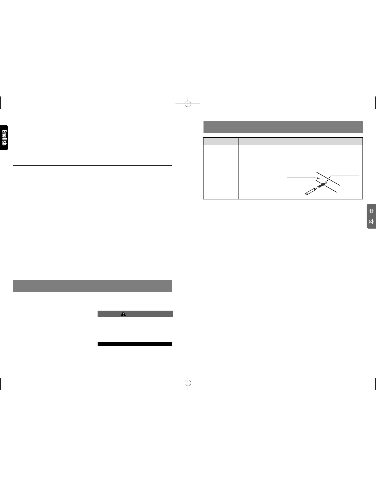
11. 故障排除
現象
按鍵時無反應。
原因
由于噪聲等原因微處理器
工作異常。
措施
用細棒等按壓位于 5.1ch 環繞聲解碼器側面的復
原開關[RESET]。
應注意按復原開關[RESET]時,所存儲的全部標題
及其他數據將被清除。
5.1ch 環繞聲
解碼器
復原開關[RESET]
280-7805-00
8 DVH920
2. FEATURES
DVH920 4DVH920 3
3. SPECIFICATIONS
Digital/Analog Processing Section
Frequency response:
20 Hz - 44 kHz (Linear PCM 96 kHz)
S/N ratio:
95 dB or more
(IHF-A, sound-field effects OFF)
Separation:
80 dB or more (with digital input)
Total harmonic distortion:
0.01% or less (with digital input)
Analog output / impedance:
4 V / 330 Ω(6ch output)
DSP/EQ section
DSF:
6 patterns
P.EQ functions
Band: 3-band x 3 ch (center, front, surround)
F (central frequency):
20 Hz - 20 kHz(1/3 octave step, 31 points)
Q curve: 1 - 20 (5 points)
Gain: ±12 dB
General
Power supply:
DC 14.4 V (10.8 - 15.6 V)
Ground:
Negative ground
Power consumption:
480 mA
Dimensions:
230 (W) x 25 (H) x 170 (D) mm
Weight:
900 g
Note:
• Specifications and design are subject to change
without notice for further improvement.
■
Onboard DTS/Dolby Digital/Pro Logic
II
Decoder
• Independent playback of DVD video surround format DTS, Dolby Digital 5.1ch.
• Utilizes Pro Logic II with advanced digital matrix technology for 5.1 channel decoding of 2-chan-
nel CD and radio.
■
Newly developed 32-bit DSP LSI with advanced processing performance
• DSF function allows application of 6 sound field effect patterns following decoding of DTS, Dolby
Digital 5.1ch format, or Dolby Pro Logic II signals.
• The parametric equalizer function allows you to adjust the frequency characteristics to suit the
car.
■
High precision 96 kHz / 24 bit D/A converter used in all channels
■
New-type digital input connectors
• New digital input connectors support sampling rate of 96 kHz.
32 kHz: MP3 etc.
44.1 kHz: CD, CD-R, CD-RW, MD
48 kHz: DVD video
96 kHz: DVD video
■
Supports analog input connectors (RCA 2ch)
(when optional control unit is connected)
• When center unit or other RCA 2ch output is connected to analog input connectors, Dolby Pro
Logic II function can convert to 5.1ch output.
■
Thin-line chassis can be installed beneath seat.
■
DTS
• DTS is an abbreviation for Digital Theater System; while this system possesses the same 5.1ch
format as Dolby Digital, its higher quantity of recorded data results in higher quality sound.
∗Manufactured under license from Digital Theater Systems, Inc. US Pat. No. 5,451,942, 5,956,674,
5,974,380, 5,978,762 and other world-wide patents issued and pending.
“DTS” and “DTS Digital Surround” are registered trademarks of Digital Theater Systems, Inc. ©
1996, 2000 Digital Theater Systems, Inc. All Rights Reserved.
■
Dolby Pro Logic
II
• Using the newest in digital matrix technology, Dolby Pro Logic II is a matrix decoder technology
which further improves earlier Dolby Pro Logic. This new technology produces superb 5.1ch
sound even with CDs and other stereo sources.
The surround channel is converted to full-band (20 Hz-20 kHz) stereo, thus allowing stereo
sources to be enjoyed with the impact of 5.1ch sound. Four modes can be set in accordance with
the playback source, including MUSIC mode, MATRIX mode, MOVIE mode, and VIRTUAL mode.
• Dolby Digital is a totally discrete digital 5.1 channel format. Signals for the front 3 channels, 2
surround channels, and the low-frequency 0.1 channel are recorded discretely, so no crosstalk
occurs between channels, and the sense of placement and depth of the sounds is reproduced
faithfully.
∗Manufactured under license from Dolby Laboratories.
“Dolby”, “Pro Logic” and duble-D symbol are trademarks of Dolby Laboratories.
Be sure to unfold and read the next page. / Veuillez déplier et vous référer à la page suivante.
Cerciórese de desplegar y de leer la página siguiente.
■
Digital Inputs (When Optical Digital Cable is Connected)
• When optical digital cable is used to connect components like a DVD changer, the digital signals
are given precedence in processing.
• When Dolby Digital (other than 2ch), DTS, Linear PCM (96 kHz) or other digital signals are input,
the Dolby Pro Logic II mode can be selected, but the mode will not perform ordinary audio pro-
cessing.
• When MP3 (32 kHz) and Linear PCM (96 kHz) digital signals are input, the Parametric Equalizer
(P.EQ) function can be operated, but it will not perform audio processing.
■Sound Effects and Sound-Field Compensation with Digital and Analog Signals
Input Signal Sampling Rate Recording Recording PLII DSF P.EQ
Format channels function function function
fs=32 kHz MP3 etc. 2ch O O ×
fs=44.1 kHz CD-DA 2ch O O O
Linear PCM 2ch O O O
Digital signals fs=48 kHz Dolby Digital 2ch O O O
(Not 2ch) ×OO
DTS 2ch~5.1ch ×OO
fs=96 kHz Linear PCM 2ch ×O×
Analog signals — — 2ch O O O
O: Adjustable ×: Adjustable without audio processing
(Analog signals: when connected to CeNET connectors or analog input connectors)
■
Speaker System
• To get maximum enjoyment from the
sound-field functions of this component,
the use of a 5.1ch speaker system is rec-
ommended. To demonstrate optimum
audio response, modify the adjust
mode’s default settings for “SP-SEL,”
“FILTER,” “SP-GAIN,” and “DELAY” in
accordance with the composition of your
speaker system (see P.10-11).
Front
speaker (L) Center speaker Front
speaker (R)
Rear
speaker (L)
Rear
speaker (R)
Sub-woofer
■
DVD Video
• When playing a DTS-compatible DVD video or music CD, some noise may be heard for the short
interval required for this unit to detect the DTS signal.
• During playback of Dolby digital or DTS source, some sound interruption may be heard if the
search/skip/pause modes are operated before playback.
×2×1×4×4×2
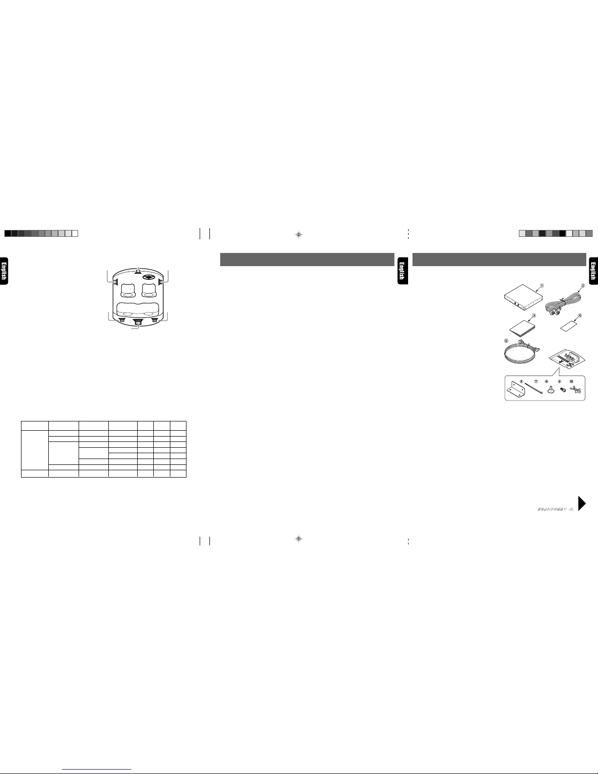
List of accessories
1DVH920 ...................................................... 1
2CeNET cable (5 m) ..................................... 1
3Owner’s manual ......................................... 1
4Warranty ..................................................... 1
5Optical Digital Cable (5 m) ......................... 1
6Mounting brackets ...................................... 2
7Cord clamps ............................................... 2
8Canoe clips ................................................. 4
9Mounting screws ........................................ 4
0Cable Clip ................................................... 1
280-7805-00_02-08 (En) 2/21/02, 4:12 PM3
280-7805-00
5DVH920 6DVH920 DVH920 7
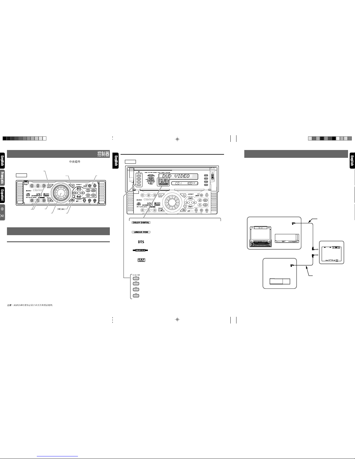
4.
CONTROLS/LES COMMANDES/CONTROLES/
5. NOMENCLATURE
Names of Buttons
Center Unit
[EQ] button:
•Press to enter the EQ mode.
•When the button is pressed and hold for 1 sec-
ond or longer, the mode is turned on or off.
[ENT] button:
•Used as “Enter button”while the unit is in the
adjust mode.
[ADJ] button:
•Press and hold the button for 1 second or longer
to enter the adjust mode.
[a], [d] buttons:
•Used for selecting the respective adjustment
items.
[ROTARY] knob:
•Use the knob to perform various settings.
[DIRECT] button:
•Used for D.S.F. menu selection.
[VSE] button:
•Press the button to turn on the DSF.
•After DSF is selected, press and hold the [VSE]
button for 1 second or longer to turn to off DSF
effect.
[PLII] button:
•Press the button to turn on the PLII. Each time
the button is pressed, PLII mode changes fol-
lowing order:
MUSIC mode ➜MATRIX mode ➜MOVIE
mode ➜VIRTUAL mode ➜mode off
Center Unit Display
6. CONFIRM BEFORE OPERATION
Note: Be sure to unfold this page and refer to the front diagrams as you read each chapter.
Remarque: Veuillez déplier cette page et vous référer aux schémas quand vous lisez chaque chapitre.
Nota: Cuando lea los capítulos, despliegue esta página y consulte los diagramas.
■
Center unit / Unitécentrale / Unidad central /
[VSE]
[EQ][ENT]
[ADJ]
[PLII ]
[DIRECT]
[ROTARY]
DXZ925
DXZ925
: MUSIC mode
: MATRIX mode
: MOVIE mode
: VIRTUAL mode
: DOLBY DIGITAL indicator
Lights when playing Dolby Digital sound from the Digital input con-
nector.
: LINEAR PCM indicator
Lights when playing linear PCM sound from the Digital input con-
nector.
: DTS indicator
Lights when playing DTS sound from the Digital input connector.
: DOLBY PLII (Dolby Pro Logic II) indicator
Lights when selecting the various Dolby Pro Logic II function modes.
: D.S.F. indication
(DCZ625)
(VCZ625)
(DVH920)
(VRX925VD)
DCA-005 (5m)
DCA-008 (1.5m)
DCA-006 (5m)
■
DOLBY PL
II
indicators
This component does not operate independently as an stand-alone unit and must be used in conjunc-
tion with an operational Clarion Center Unit (CeNET supported), or a 5.1 CH surround decoder control
unit (DVC920).
See section “10. SYSTEM EXPANSION”(P. 16) for details regarding other compatible components.
■
CeNET Cable
The CeNET cable used must not be over 20 m long (including the length of the CeNET branch cable
CCA-519). When making connections be sure that your cable length is not over 20 m.
■
Optical Digital Cables (sold separately or furnished with DVH920)
Optical digital cables (sold separately or furnished with DVH920) connected to this unit differ depend-
ing on the model of CeNET component involved.
Consult your dealer regarding the kind of optical digital cable required for your component.
Likewise, consult the operating instructions accompanying your component for details regarding con-
nections.
Ce-NET connections
DVD/wide 7”AV center unit
CeNET DVD changer
(Gray)
5.1ch surround
decoder
CeNET CD changer
(Gray)
(Black)
(Black)
Note:
•When the DVH920 is connected, the P.E.Q., PO-
SITION, VSE, BAS/TRE, and TITLE inputs used
with the DXZ925 can no longer be used.
280-7805-00_02-08 (En) 2/21/02, 4:12 PM4

280-7805-00
DVH920 9
Operations (DXZ925) Note: Be sure to read this chapter referring to the front diagrams
of chapter “4. CONTROLS” on page 5 (unfold).
7. OPERATIONS
Dolby Pro Logic
II
Menu Selection
About the Dolby Pro Logic II Mode
• Initial setting is [PL II OFF].
■MUSIC mode
• Suitable for CDs and other stereo sources.
■MATRIX mode
• Suitable for AM/FM radio sources.
■MOVIE mode
• Suitable for DVD video movies.
■VIRTUAL mode
• Suitable for movies and other audio sources.
1. Press the [PL II]button to select the desired
mode.
Each time the button is pressed, the mode al-
ternates as follows:
[MUSIC] ➜[MATRIX] ➜[MOVIE] ➜
[VIRTUAL] ➜[PLII OFF]
Note:
• The PL
II
menu cannot be selected when [SP-SEL]
has been used to set center speakers and rear
(surround) speakers to [OFF].
DSF Setting
DSF(Digital Sound Field) makes it possible
through sound simulation to enjoy the acoustic
experience you would have in a concert hall or a
live performance hall.
• Initial setting is [OFF].
1. Press the [VSE] button to enter DSF mode.
2. Press the [DIRECT] button to select DSF
menu.
1HALL: Large concert hall.
2CHURCH: Charch with a vaulted ceiling.
3STADIUM: Large stadium without roof or
walls.
4LIVE: Live performance hall, larger than a
jazz club.
5JAZZCLUB: Jazz club with a low ceiling.
6THEATER: Movie or drama theater.
3. Press the [VSE] button to return to the previ-
ous mode.
4. Press and hold the [VSE] button for 1 second
or longer so the DSF effect is turned on or off.
Setting parametric equalizer (P.EQ)
The parametric equalizer function allows you to
adjust the frequency characteristics to suit the car.
• The initial value provides the following set-
tings for all speakers.
FREQ = 1kHz, Q =1, GAIN = 0dB
• Some distortion may be heard if the [ROTARY]
knob is turned rapidly.
1. Press the [EQ] button to enter P.EQ mode.
2. Press the [a] or [d] button to select adjust-
ment item. Each time the [a] or [d] button
is pressed, the indications change as shown
below.
[SIGNAL] ➜[SP-SEL] ➜[BAND] ➜
[FREQ] ➜[Q] ➜[GAIN] ➜[SIGNAL]
●SIGNAL: selects the adjustment signal.
•SGNL P-NOIS: set when pink noise is to
be used
•SGNL MUSIC: set to use music signals
●SP-SEL: selects the speakers whose P.EQ
value is to be adjusted.
•SP FRONT: front speaker
•SP CENTER: center speaker
•SP SURROUND: surround speaker
●BAND: selects the frequency band (Band
1 to 3) to adjust.
●FREQ: selects the frequency for bands 1 to
3.
• The range of adjustments is from 20 Hz
to 20 kHz.
●Q: sets the Q curve.
• Larger numbers produce a sharper Q
characteristics curve while smaller num-
bers produce gentler characteristics.
Adjustments are made in the range Q1 to
Q20.
●GAIN: adjusts the output level.
• Adjustments are made in the range -12
dB to +12 dB.
3. Turn the [ROTARY] knob clockwise or coun-
terclockwise to adjust each value.
4. Press the [EQ] button to return to the previ-
ous mode.
5. Press and hold the [EQ] button for 1 second
or longer so the EQ effect is turned on or off.
• Initial setting is [OFF].
280-7805-00_09-20 (En) 2/21/02, 4:13 PM9

10 DVH920
280-7805-00
Turning speakers on or off (SP-SEL)
The center speaker, rear (surround) speakers
and sub woofer have to be set to on or off to
achieve maximum sound quality.
•The initial setting is [ON].
1. Press and hold the [ADJ] button for 1 second
or longer to enter adjust mode.
2. Press the [a] or [d] button to change to the
[SP-SEL ] display.
3. Press the [ENT] button to display the adjust-
ment item.
Press the [a] or [d] button to select [CEN-
TER-SP], [SURROUND-SP] or [SUB-
WOOFER].
•CENTER-SP: center speaker
•SURROUND-SP: rear (surround) speaker
•SUB-WOOFER: subwoofer
4. Turn the [ROTARY] knob clockwise or coun-
terclockwise to select [ON] or [OFF].
•ON: Speaker installed
•OFF: Speaker not installed
•When a sub woofer is used, set [ON+], [ON-]
or [OFF]. The normal setting is [ON+], but
use the [ON-] setting when this provides a
better effect for low frequency range.
5. Press the [ADJ] button to return to the origi-
nal mode.
Setting speaker filter frequency
(FILTER)
This function is used to set a filter frequency that
suits the frequency characteristics of the used
speakers.
•The initial value of [FRONT HPF], [SRD HPF]
is [THRGH] (no filter).
•The initial value of [CENTER HPF], [SUB-W
LPF] is [120 Hz]
•A speaker that was turned off in the Section
“Turning speakers on or off (SP-SEL)”is not
displayed.
1. Press and hold the [ADJ] button for 1 second
or longer to enter adjust mode.
2. Press the [a] or [d] button to change to the
[FILTER ] display.
3. Press the [ENT] button to display the adjust-
ment item.
4. Press the [a] or [d] button to select the
speaker to adjust.
•FRONT HPF: high pass filter for front speak-
ers
•CENTER HPF: high pass filter for the cen-
ter speaker
•SRD HPF: high pass filter for the rear (sur-
round) speakers
•SUB-W LPF: low pass filter for the sub-
woofer
5. Turn the [ROTARY] knob clockwise or coun-
terclockwise to select the frequency.
•In case of [FRONT HPF] and [SRD HPF],
the frequency is 50 Hz, 80 Hz, 120 Hz and
[THRGH] (no filter).
•In case of [SUB-W LPF], [CENTER HPF] the
frequency is 50 Hz, 80 Hz or 120 Hz.
6. Press the [ADJ] button to return to the origi-
nal mode.
Adjusting speaker output level
(SP-GAIN)
Use the built-in test tone function of the unit to
adjust the speaker output level to the same level.
•The initial value is [0 dB].
•A speaker that was turned off in the Section
“Turning speakers on or off (SP-SEL)”is not
displayed.
1. Press and hold the [ADJ] button for 1 second
or longer to enter adjust mode.
2. Press the [a] or [d] button to change to the
[SP-GAIN ] display.
3. Press the [ENT] button to display the adjust-
ment item.
•In the adjustment mode, the test tone is out-
put from the selected speaker.
4. Press the [a] or [d] button to select the
speaker to adjust.
•Each time the [DISP] button is pressed, the
indications change as shown below.
FRONT- : front left speaker
CENTER: front center speaker
FRONT- : front right speaker
SURROUND : right rear (surround)
speaker
SURROUND : left rear (surround) speaker
SUB-WOOFER: rear subwoofer
Setting Acoustic Features (DXZ925)
280-7805-00_09-20 (En) 2/21/02, 4:13 PM10

280-7805-00
DVH920 11
Setting Acoustic Features (DXZ925)
5. Turn the [ROTARY] knob clockwise or coun-
terclockwise to adjust the gain.
•The adjustment range is –10 dB to +10 dB.
6. Press the [ADJ] button to return to the origi-
nal mode.
Adjusting speaker delay time
(DELAY)
The timing when the sound of each speaker
reaches the listening position depends on speaker
installation and the size of the car. Adjust the delay
time of each speaker so that the sound of all speak-
ers reach the listening position at the same time as
the sound from the front speakers.
•The initial value is [0 ms].
•A speaker that was turned off in the Section
“Turning speakers on or off (SP-SEL)”is not
displayed.
1. Press and hold the [ADJ] button for 1 second
or longer to enter adjust mode.
2. Press the [a] or [d] button to change to the
[DELAY ] display.
3. Press the [ENT] button to display the adjust-
ment item.
4. Press the [a] or [d] button to select the
speaker to adjust.
•CTR-SP: center speaker
•SRD-SP: rear (surround) speaker
5. Turn the [ROTARY] knob clockwise or coun-
terclockwise to select the delay time.
•The [CTR-SP] adjustment range is 0 to 5 ms.
•The [SRD-SP] adjustment range is 0 to 15
ms.
6. Press the [ADJ] button to return to the origi-
nal mode.
Setting the Dolby digital functions
(Dolby D)
●
Dynamic range compression function
(D-RANGE):
This function compresses the dynamic range of
Dolby digital to maintain low level sounds such
as actor conversation and suppress loud sound
volumes.
These functions are only available on Dolby digi-
tal DVD discs.
1. Press and hold the [ADJ] button for 1 second
or longer to enter adjust mode.
2. Press the [a] or [d] button to change to the
[Dolby D] display.
3. Turn the [ROTARY] knob clockwise or coun-
terclockwise to select the value from [MAX],
[STD] or [MIN].
•The initial value is [MAX].
•MAX: maximum dynamic range mode of
the original source
•STD: recommended mode for standard lis-
tening
•MIN: the most compressed dynamic range
mode that renders even low sounds easy
to hear.
4. Press the [ADJ] button to return to the origi-
nal mode.
MUSIC Mode Fine Adjustments (PL
II
CONT)
When MUSIC Mode has been selected on the
PL II menu, finer adjustments can be made when
desired.
CTR WIDTH is not available when center speaker
is turned off in the section “Turning speakers on
or off (SP-SEL)”.
1. Press and hold the [ADJ] button for 1 second
or longer to enter adjust mode.
2. Press the [a] or [d] button to show the [PL
II CONT ] display.
3. Press the [ENT] button to display the adjust-
ment item.
4. Press the [a] or [d] button to select the item.
280-7805-00_09-20 (En) 2/21/02, 4:13 PM11

12 DVH920
280-7805-00
Setting Acoustic Features (DXZ925)
●PANORAMA (Y or N):
Selecting PANORAMA mode will extend the
front sound field image to the rear. If sur-
round effect does not seem to be presented
sufficiently, select the setting position [Y].
•The initial setting is [N].
●DIMENSION (0 to 6):
Selecting DIMENSION mode will shift the
sound field image to the front or the rear. If
the balance of the sound field image is too
much pulled towards the front or rear, the
balance front/rear can be corrected.
The adjusting value 3 is the center position.
The range of 3 to 0 shifts the balance front/
rear to the front. The range of 3 to 6 shifts
the balance front/rear to the rear.
•The initial value is [3].
●CTR WIDTH (0 to 7):
Selecting CTR WIDTH mode will adjust the
localization of the center channel between
the center speaker and the front speaker L/
R.
Distributing the center channel sound to the
right and left will increase the integrated
sound field image, providing you with an
natural spatial feeling of sound.
Setting to the value 0 will produce the cen-
ter sound with the center speaker.
Setting to the value 7 will distribute the cen-
ter sound to the front speaker L/R as the
existing stereo sound does.
•The initial value is [3].
5. Turn the [ROTARY] knob clockwise or coun-
terclockwise to adjust the value.
6. Press the [ADJ] button to return to the origi-
nal mode.
280-7805-00_09-20 (En) 2/21/02, 4:13 PM12
280-7805-00
DVH920 13
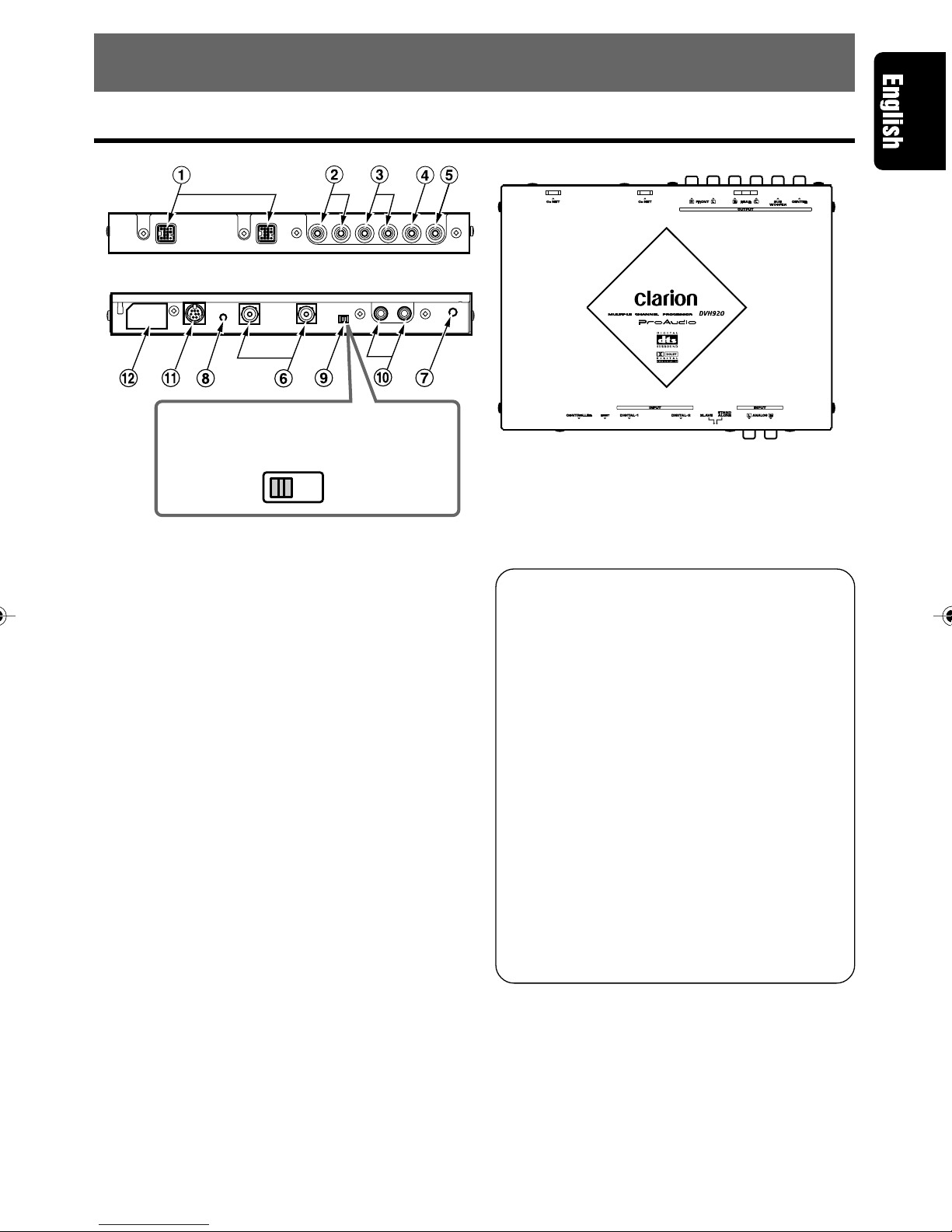
8. WIRING TECHNIQUES
Name of Parts
SLAVE STAND
ALONE
1CeNET connectors
Connect to center unit using CeNET cable.
2Front RCA output connectors.
Connect to external power amplifier using
RCA pin cable.
3Rear RCA output connectors
Connect to external power amplifier using
RCA pin cable.
4Sub-woofer RCA output connectors
Connect to external power amplifier using
RCA pin cable.
5Center speaker RCA output connectors
Connect to external power amplifier using
RCA pin cable.
6Digital input connector
Connect to DVD/CD changer using optical
digital cable (sold separately or included).
* Connect to black connector side
7Cable clip hole.
Insert cable clip to hold optical digital cable in
place.
8RESET switch
Press to reset circuitry if no sound is pro-
duced.
Note:
•Be sure the CeNET cable is connected when
pressing the [RESET] switch.
Use When Connecting Optional
Control Unit (DVC920)
9[STAND-ALONE / SLAVE]switch
•Set to STAND ALONE when connecting
a control unit.
•Leave at SLAVE position when no con-
trol unit is connected.
0Analog input connectors (RCA)
Connect to center unit’s RCA 2ch output.
Note:
•The following are enabled only when a con-
trol unit is connected.
!Control unit 8P mini DIN plug
Connect to control unit.
@Control unit power connector
Connect control unit’s power cable here.
* Leave tape in place when not in use.
[STAND-ALONE/SLAVE]switch
* The factory default setting is SLAVE
position.
280-7805-00_09-20 (En) 2/21/02, 4:13 PM13
14 DVH920
280-7805-00
How to Wire This Unit
CAUTION
Throughout the process of wiring this unit,
disconnect the negative (–) terminal of your
automobile’s battery, and leave it discon-
nected until completely finished. Handling
wires while the terminal is connected could
result in dangerous electrical shock or injury
if an accidental short circuit should occur.
Perform the settings and
connections in the order
indicated by the drawing
below.
CeNET connector
CeNET cable
Sliding cap
Optical Digital cable
(black connection)
Cable clip
1
CeNET Cable
•To connect a CeNET cable, hold it with the
connector facing as shown, and insert se-
curely.
•When disconnecting a CeNET cable, grasp
the slide cap and squeeze gently.
2
Optical Digital Cable (sold separately)
•Insert the black connector securely into the
digital signal input connector until it locks.
The cable clip can be used to secure up to
two optical digital cables.
•When disconnecting a optical digital cable,
squeeze the tabs at the right and left sides
of the connector, and pull gently.
Note:
•The optical digital cable should not be bent
with a gentle arc radius of 1.5 cm or less. If it
is bent sharper than this, the performance of
the cable will be greatly reduced and the cable
may be damaged.
3
RCA Pin Cable (sold separately)
•When connecting an RCA pin cable, be sure
to confirm the source of the connection first.
4
[RESET] switch
•Following completion of wiring, press the
[RESET] switch to return to default settings.
Note:
•Always turn the main [POWER] switch [OFF]
before connecting or disconnecting digital fiber-
optic cables.
Note:
•Route the CeNET cable with plenty of extra
room so that the connector will not become
disconnected accidentally.
Squeeze
right/left tabs
280-7805-00_09-20 (En) 2/21/02, 4:13 PM14
280-7805-00
DVH920 15
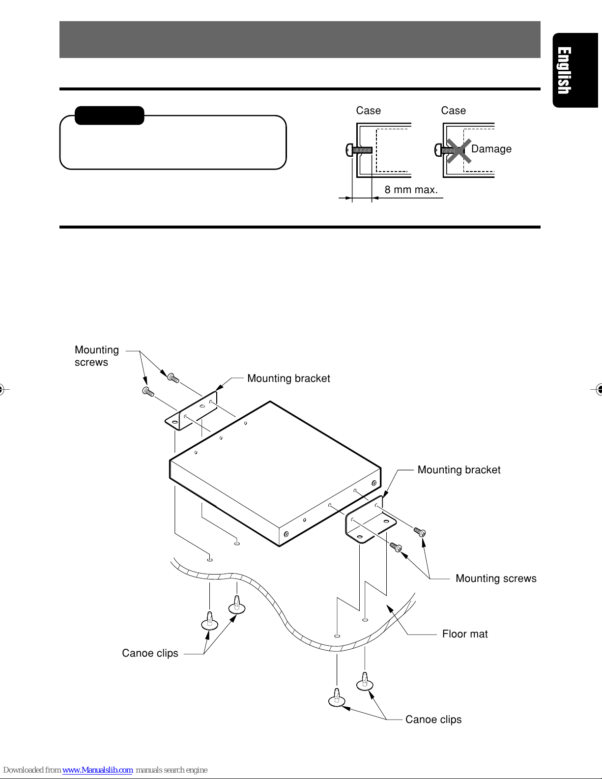
9. INSTALLATION
Installation Precautions
CAUTION!
•Install correctly, using only the screws supplied
as accessories. Using other screws may re-
sult in damage or injury.
Installation Example (for installation beneath seat)
1. Use the supplied screws (M4x8) to attach the accessory mounting bracket to the sides of the unit.
•The main unit’s case has been provided with 3 screw holes on either side. Select the screw holes
required for your installation conditions.
2. Position the unit on the floor mat, then mark and open holes in the floor mat so they are aligned with
the mounting bracket’s holes.
3. Press the accessory canoe clips from the underside upward through the mat and into the mounting
bracket holes.
;;;;;;;;;;;;
;;;;;;;;;;;;
;;;;;;;;;;;;
;;;;;;;;;;;;
;;;;;;;;;;;;
@@@@@@@@@@@@
@@@@@@@@@@@@
@@@@@@@@@@@@
@@@@@@@@@@@@
@@@@@@@@@@@@
ÀÀÀÀÀÀÀÀÀÀÀÀ
ÀÀÀÀÀÀÀÀÀÀÀÀ
ÀÀÀÀÀÀÀÀÀÀÀÀ
ÀÀÀÀÀÀÀÀÀÀÀÀ
ÀÀÀÀÀÀÀÀÀÀÀÀ
Case Case
Damage
8 mm max.
Mounting
screws
Mounting bracket
Floor mat
Mounting bracket
Mounting screws
Canoe clips
Canoe clips
280-7805-00_09-20 (En) 2/21/02, 4:13 PM15

16 DVH920
280-7805-00
(VCZ625)
(DVH920)
SLAVE STAND
ALONE
LINE
IN
LINE
OUT
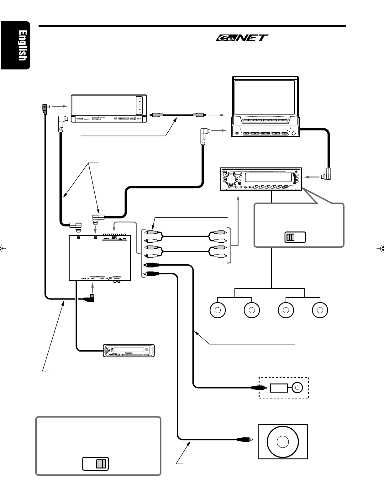
10. SYSTEM EXPANSION
Example: VRX925VD + DVD Changer
■
Your AV Center Unit may be used to control the DVH920 surround
decoder. Installing the DVH920 will allow you to enjoy DTS and Dolby
Digital 5.1ch sound.
RCA video cable (yellow);
(furnished with DVD changer)
CeNET DVD Changer
Gray
CeNET Cable (furnished with
component to be connected)
RCA pin cable
(sold separately)
5.1ch Surround
Decoder
Black
Optical Digital cable (sold separately)
DCA-005 (5 m) (furnished with DVH920)
DCA-008 (1.5 m)
*
Connect properly in accordance with
color of connectors
Powered center speaker
Built-in amplifier
Amplifier
RCA pin cable
(sold separately)
Powered sub-woofer
Built-in amplifier
Set the 5.1ch surround decoder’s
[STAND-ALONE / SLAVE] switch to
the [SLAVE] position.
Speaker wire
Front speakers Rear speakers
RCA pin cable
(furnished with Center Speaker)
Black
DVD / Wide 7”AV
Center Unit
Set the [LINE-IN/
OUT] switch to the
LINE-IN position.
280-7805-00_09-20 (En) 2/21/02, 4:14 PM16

280-7805-00
DVH920 17
(VCZ625)
(DVH920)
SLAVE STAND
ALONE
Example : DXZ925 + DVD Changer + Monitor
■
Your Center Unit may be used to control the DVH920 surround decoder.
Installing the DVH920 will allow you to enjoy DTS and Dolby Digital
5.1ch sound.
1 DIN TV
Gray
RCA video cable (yellow);
(furnished with DVD changer)
CeNET DVD Changer
RCA pin cable
(sold separately)
4CH power amplifier
5.1ch surround
decoder
Set the 5.1ch surround decoder’s
[STAND-ALONE / SLAVE] switch to
the [SLAVE] position.
Speaker wire
Front speakers Rear speakers
Powered center speaker
Built-in amplifier
Amplifier
RCA pin cable
(furnished with center speaker)
Powered sub-woofer
Built-in amplifier
RCA pin cable
(sold separately)
Optical Digital cable (sold separately)
DCA-005 (5 m) (furnished with DVH920)
DCA-008 (1.5 m)
*
Connect properly in accordance with
color of connectors
CeNET Cable (furnished with
component to be connected)
1-DIN Center Unit
Black
280-7805-00_09-20 (En) 2/21/02, 4:14 PM17
18 DVH920
280-7805-00
(DXZ825)
(VCZ625)
(DVC920)
SLAVE STAND
ALONE
LINE
IN
LINE
OUT
(DVH920)
POWER
DSF
ADJUSTA-MODE
SOURCE
Example: DXZ825 + DVD Changer + Monitor
■
Even if you have an Clarion Center Unit ( compliant) that
cannot control 5.1ch surround sound, installing a Control Unit (DVC920)
will make it possible to operate the component successfully.
RCA video cable (yellow);
(furnished with DVD changer)
CeNET DVD Changer
Gray
CeNET Cable (furnished with
component to be connected)
RCA pin cable
(sold separately)
5.1ch Surround
Decoder
Black
Control Unit for 5.1ch
Surround Decoder
Optical Digital cable (sold separately)
DCA-005 (5 m) (furnished with DVH920)
DCA-008 (1.5 m)
*
Connect properly in accordance with
color of connectors
Powered center speaker
Built-in amplifier
Amplifier
RCA pin cable (sold separately)
Powered sub-woofer
Built-in amplifier
Set the 5.1ch surround decoder’s
[STAND-ALONE / SLAVE] switch
to the [STAND-ALONE] position.
1-DIN TV
1-DIN Center Unit
Speaker wire
Front speakers Rear speakers
RCA pin cable
(furnished with Center Speaker)
Set the [LINE-IN/OUT] switch
to the LINE-IN position.
280-7805-00_09-20 (En) 2/21/02, 4:14 PM18
280-7805-00
DVH920 19
Nothing happens
when buttons are
pressed.
11. IN CASE OF DIFFICULTY
Problem
The microprocessor has
malfunctioned due to noise,
etc.
Use a narrow stick to press the [RESET] switch on
the side of the 5.1ch surround decoder. Note that
when the [RESET] switch is pressed, all titles and
other data placed in memory will be erased.
Cause Measure
5.1ch surround
decoder
[RESET] switch
280-7805-00_09-20 (En) 2/21/02, 4:14 PM19

20 DVH920
280-7805-00
280-7805-00_09-20 (En) 2/21/02, 4:14 PM20

280-7805-00
DVH920 21
Table des matières
1. PRÉCAUTIONS ............................................................................................................................. 21
2. CARACTÉRISTIQUES .................................................................................................................. 22
3. SPÉCIFICATIONS ......................................................................................................................... 23
4. LES COMMANDES ......................................................................................................................... 5
5. NOMENCLATURE ......................................................................................................................... 24
Nom des touches ........................................................................................................................... 24
Affichage d’unité centrale .............................................................................................................. 25
6. VÉRIFICATIONS AVANT LA MISE EN MARCHE ....................................................................... 26
7. FONCTIONNEMENT ..................................................................................................................... 28
Démarches (DXZ925) .................................................................................................................... 28
Réglage des caractéristiques acoustiques (DXZ925) .................................................................. 29
8. MÉTHODE DE CÂBLAGE ............................................................................................................ 32
Nom des pièces ............................................................................................................................. 32
Câblage de cette unité................................................................................................................... 33
9. INSTALLATION ............................................................................................................................. 34
Précautions à l’installation ............................................................................................................. 34
Exemple d’installation .................................................................................................................... 34
10. EXPANSION DU SYSTÈME ......................................................................................................... 35
Exemple : VRX925VD + Changeur DVD ...................................................................................... 35
Exemple : DXZ925 + Changeur DVD + Moniteur ......................................................................... 36
Exemple : DXZ825 + Changeur DVD + Moniteur ......................................................................... 37
11. EN CAS DE DIFFICULTÉ............................................................................................................. 38
Nous vous remercions d’avoir acheté ce produit Clarion.
* Lisez tout ce mode d’emploi avant de mettre l’appareil en service.
* Après la lecture de ce manuel, conservez-le dans un endroit pratique (par exemple dans la boîte à
gants).
* Vérifiez le contenu de la carte de garantie jointe et conservez-la précieusement avec ce manuel.
* Le DVH920 peut être contrôlé par les unités centrales Clarion DXZ925 et VRX925VD, compatibles
CeNET. Ce mode d’emploi signale les fonctions qui changent du fait de la connexion du DVH920 à
un des composants ci-dessus.
1. PRÉCAUTIONS
1. Le DVH920 peut facilement être endommagé
par une humidité ou une température élevées.
Veillez à ce que l’intérieur du véhicule soit
toujours propre et bien ventilé.
2. Ne soumettez jamais le DVH920 à des chocs
violents et n’ouvrez pas son coffret, car il
pourrait en être endommagé.
3. Utilisez un chiffon doux et sec pour nettoyer
le DVH920. N’employez pas de chiffon dur,
de diluant pour peinture, d’alcool, etc. Pour
enlever les fortes taches, humectez un chiffon
doux avec un peu d’eau froide ou tiède et
éliminez doucement la saleté.
4. Lorsque le module principal est commuté aux
annonces sur la circulation routière ou lors de
la réception à interruption PTY en utilisant le
DVH920, les effets du DVH920 sont inopérants.
5. Le son de certaines plages semblera distordu
pendant le réglage, mais ceci est normal et
ne doit pas vous préoccuper.
PRÉCAUTION
Des changements ou modifications non
approuvés explicitement par le fabricant
peuvent annuler le droit de l’utilisateur de se
servir de cet appareil.
INFORMATIONS AUX UTILISATEURS :
Des changements ou modifications apportés
àcet appareil et non approuvés par le
fabricant annuleront la garantie.
280-7805-00_21-38 (Fr) 2/21/02, 4:14 PM21

22 DVH920
280-7805-00
2. CARACTÉRISTIQUES
■
Décodeur DTS / Dolby Digital / Pro Logic II àbord
•Lecture indépendante de DVD vidéo format surround DTS, Dolby Digital 5.1 canaux.
•Utilisation du Pro Logic II avec technologie àmatrice numérique avancée pour décodage 5.1
canaux de CD et radio 2 canaux.
■
Circuit intégréDSP 32 bits de conception nouvelle àperformances de
traitement excellentes
•La fonction DSF autorise l’application de 6 motifs d’effet de champ sonore après le décodage
des signaux de format DTS, Dolby Digital 5.1 canaux, ou Dolby Pro Logic II.
•La fonction d’égaliseur paramétrique vous permet d’ajuster les caractéristiques de fréquence en
fonction de la voiture.
■
Convertisseur N/A 24 bits / 96 kHz de haute précision agissant sur tous
les canaux
■
Connecteurs d’entrée numérique d’un type nouveau
•Nouveaux connecteurs d’entrée numérique acceptant le taux d’échantillonnage de 96 kHz.
32 kHz : MP3, etc.
44,1 kHz : CD, CD-R, CD-RW, MD
48 kHz : DVD vidéo
96 kHz : DVD vidéo
■
Connecteurs d’entrée analogique supportés (RCA 2 canaux)
(avec connexion du module de commande en option)
•Lorsque l’unitécentrale ou une autre sortie RCA 2 canaux est raccordée aux connecteurs d’entrée
analogique, la fonction Dolby Pro Logic II peut être convertie en sortie 5.1 canaux.
■
Châssis mince installable sous le siège
■
DTS
•DTS est une abréviation de “Digital Theater System”. Bien que ce système possède le même
format 5.1 canaux que le Dolby Digital, la quantitéplus élevée des données enregistrées fournit
des sons de meilleure qualité.
∗Fabriquésous licence de Digital Theater Systems, Brevet E-U No. 5 451, 942, 5 956, 674, 5 974,
380, 5 978, 762 et autres brevets délivrés ou en attente.
“DTS”et “DTS Digital Surround”sont des marques déposées de Digital Theater Systems, Inc. ©
1996, 2000 Digital Theater Systems, Inc. Tous droits réservés.
■
Dolby Pro Logic
II
•Faisant appel aux technologies les plus récentes du son matriciel numérique, le Dolby Pro Logic
II possède une technologie qui améliore les résultats du Dolby Pro Logic antérieur. Cette nouvelle
technologie restitue des sons 5.1 canaux superbes àpartir de CD et d’autres sources stéréo.
Le canal surround est converti en stéréo toute gamme (20 Hz - 20 kHz), ce qui permet de profiter
des sources stéréo avec l’impact de sons 5.1 canaux. Quatre modes sont disponibles en fonction
de la source de lecture, àsavoir le mode MUSIC, le mode MATRIX, le mode MOVIE et le mode
VIRTUAL.
•Le Dolby Digital est un format 5.1 canaux numériques totalement distincts. Les signaux des 3
canaux avant, des 2 canaux surround et du 0,1 canal basse fréquence sont enregistrés de façon
distincte et aucune diaphonie ne se produit donc entre eux, tandis que le sentiment de placement
et de profondeur des sons est restituéavec fidélité.
∗Fabriquésous licence de Dolby Laboratories.
“Dolby”, “Pro Logic”et le symbole double-D sont des marques de fabrique de Dolby Laboratories.
280-7805-00_21-38 (Fr) 2/21/02, 4:14 PM22

280-7805-00
DVH920 23
3. SPÉCIFICATIONS
Section de traitement Numérique/
Analogique
Réponse de fréquence:
20 Hz - 44 kHz (PCM linéaire, 96 kHz)
Rapport Signal/Bruit:
95 dB ou plus
(IHF-A, Effets de champ sonore: OFF)
Séparation:
80 dB ou plus (avec entrée numérique)
Distorsion harmonique totale:
0,01% ou moins (avec entrée numérique)
Sortie / impédance analogique:
4 V / 330 ohms (sortie 6 canaux)
Section DSP/EQ
DSF:
6 motifs
Fonction P.EQ
Bande :
3 bandes x 3 canaux (centre, avant,
surround)
F (Fréquence centrale):
20 Hz - 20 kHz (palier 1/3 octave, 31
points)
Courbe Q : 1 - 20 (5 points)
Gain : +/–12 dB
Données générales
Alimentation:
CC 14,4 V (10,8 - 15,6 V)
Mise àla masse:
Masse négative
Consommation:
480 mA
Dimensions:
230 x 25 x 170 (L x H x P) mm
Poids:
900 g
Remarque:
• Spécifications et design sous réserve de change-
ments sans préavis à des fins d’améliorations.
×2×1×4×4×2
Liste des accessoires
1Appareil DVH920 ........................................ 1
2Câble CeNET (5 m) .................................... 1
3Mode d’emploi ............................................ 1
4Garantie ...................................................... 1
5Câble optique numérique (5 m) ................. 1
6Appliques de montage ............................... 2
7Serre-fils ..................................................... 2
8Pince canot ................................................. 4
9Vis de montage........................................... 4
0Serre-câble ................................................. 1
280-7805-00_21-38 (Fr) 2/21/02, 4:15 PM23

24 DVH920
280-7805-00
5. NOMENCLATURE
Nom des touches
Unitécentrale
Touche [EQ]:
•Appuyez pour passer au mode EQ.
•Une pression prolongée pendant plus d’une
seconde sur la touche met le mode en service
et hors service.
Touche [ENT]:
•Utilisée comme “Touche de saisie”quand l’unité
est en mode de réglage.
Touche [ADJ]:
•Une pression prolongée pendant plus d’une
seconde sur la touche fait passer au mode de
réglage.
Touches [a], [d]:
•Utilisées pour sélectionner les rubriques de
réglage respectives.
Bouton [ROTARY]:
•Utilisez ce bouton pour effectuer divers
réglages.
Touche [DIRECT]:
•Utilisée pour la sélection du menu D.S.F.
Touche [VSE]:
•Appuyez sur cette touche pour mettre le DSF
en service.
•Après sélection de DSF, une pression
prolongée pendant plus d’une seconde sur la
touche met l’effet DSF hors service.
Touche [PLII]:
•Appuyez sur cette touche pour mettre le PLII
en service. A chaque pression sur la touche, le
mode PLII change dans l’ordre suivant:
Mode MUSIC ➜Mode MATRIX ➜Mode
MOVIE ➜Mode VIRTUAL ➜Mode hors
service.
280-7805-00_21-38 (Fr) 2/21/02, 4:15 PM24
Table of contents
Languages:
Other Clarion Media Converter manuals


Popular Media Converter manuals by other brands

TV One
TV One 1T-AP-216 instruction manual

IFM Electronic
IFM Electronic E7354A operating instructions

StarTech.com
StarTech.com 25SAT35HDD Quick install guide

SBS Technologies
SBS Technologies IP-OPTODA16CH4 user manual

Connective Peripherals
Connective Peripherals ES-U Series manual

Cayin
Cayin RU6 quick guide


